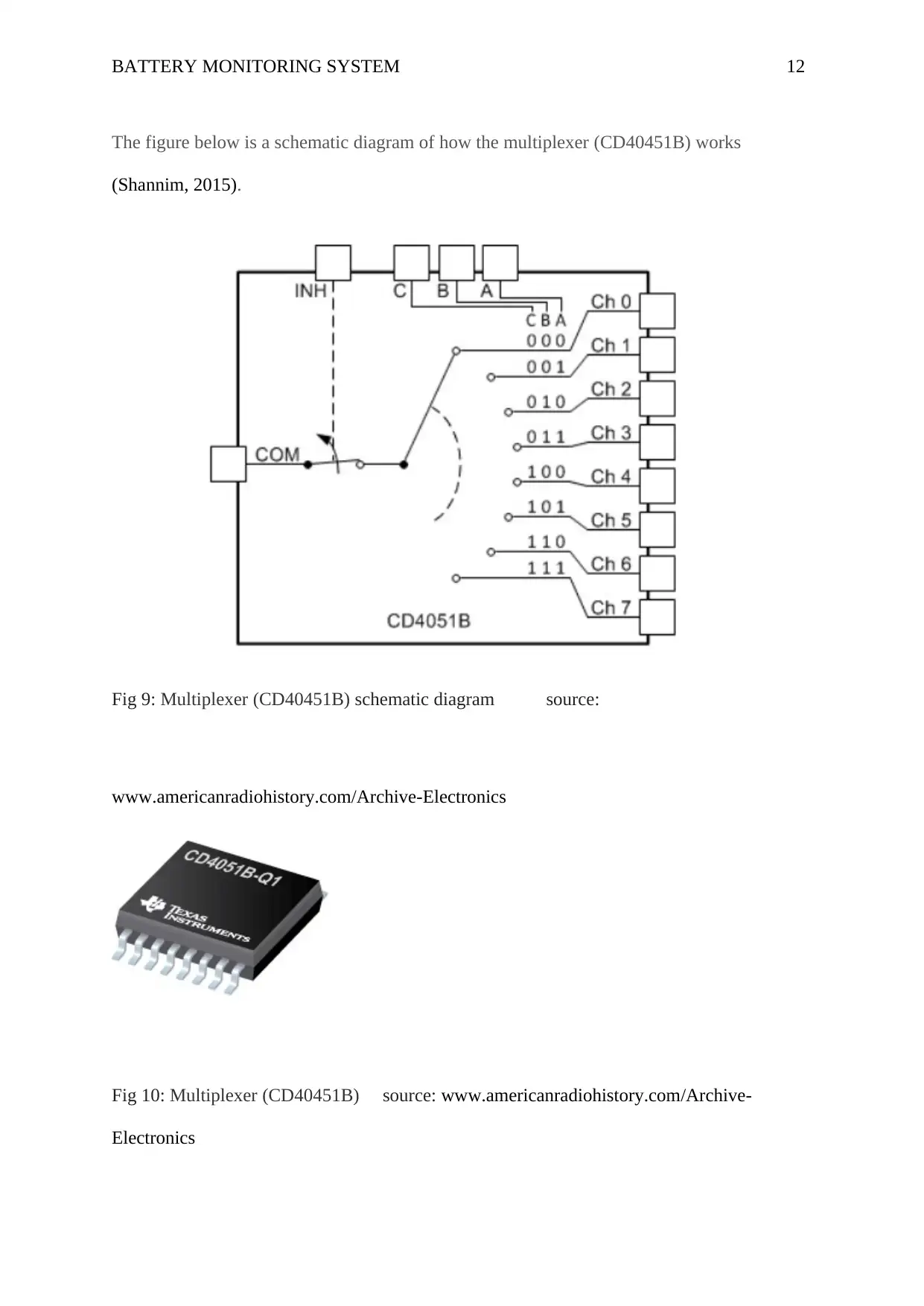
Analysis and Design of a Battery Monitoring System Report
VerifiedAdded on 2021/04/24
|17
|2521
|133
Report
AI Summary
This report provides a comprehensive analysis of battery monitoring systems (BMS), delving into their history, components, and applications. It begins with an abstract defining the core concept of a BMS, which manages rechargeable batteries by ensuring safe operating parameters and calculating secondary data. The report then explores the historical context, including the invention of the multiplexer and the discovery of lithium batteries. A literature review examines real-time automotive battery monitoring systems, battery monitoring system designs, and related projects. The core of the report focuses on key devices like the isolation amplifier (ISO24), multiplexer (CD4051B), and thermistor (LM35D), detailing their functions and schematics. Finally, the report concludes by summarizing the key findings and emphasizing the significance of BMS in modern technology. The report also includes references to support the information presented. This document is a student's contribution to Desklib, a platform offering AI-powered study tools and resources for students.

Running head: BATTERY MONITORING SYSTEM 1
BATTERY MONITORING SYSTEM
Name of Student
Institution Affiliation
BATTERY MONITORING SYSTEM
Name of Student
Institution Affiliation
Paraphrase This Document
Need a fresh take? Get an instant paraphrase of this document with our AI Paraphraser

BATTERY MONITORING SYSTEM 2
Abstract
A battery system refers to an electronic system which manages a rechargeable battery, such
as protecting/ensuring that the battery does not operate outside its safe operating areas. The
multiplexer was inverted by the French engineer Jean-Maurice-Émile Baudo in 1894.The
invention compelled the communication we have today. Isolation amplifier refers to a
category of differential amplifiers which allows measurement of very small signals in the
prescience of a common high mode by producing electrical isolation and a safety barrier for
electricity. Lithium batteries refer to the primary batteries with lithium as an anode. The
battery was discovered by Adam Heller in 1973.
Table of Contents

BATTERY MONITORING SYSTEM 3
1.0 History..................................................................................................................................4
2.0 Literature review..................................................................................................................6
2.1Real Time Automotive Battery Monitoring System.........................................................6
2.2Battery Monitoring System...............................................................................................7
2.3 Design and implementation of a battery monitoring system for the tcu engineering
department electric vehicle.....................................................................................................8
2.4 Design and Development of a Real-Time Monitoring System for Multiple Lead–Acid
Batteries Based on Internet of Things....................................................................................9
3.0 Device and description.......................................................................................................10
3.1 Isolation amplifier (ISO24).........................................................................................10
Fig 8: Isolation amplifier (ISO24)
……………………………………….................................................................11
3.2 Multiplexer (CD4051B)..............................................................................................11
3.3 Thermistor (LM35D) (0-100c)...................................................................................12
4.0 Conclusion..........................................................................................................................14
5.0 References..........................................................................................................................15
⊘ This is a preview!⊘
Do you want full access?
Subscribe today to unlock all pages.

Trusted by 1+ million students worldwide

BATTERY MONITORING SYSTEM 4
1.0 History
A battery management system refers to an electronic system which manages a rechargeable
battery, such as protecting/ensuring that the battery does not operate outside its safe operating
areas, calculating the secondary data, controlling its environment, authenticating, reporting
secondary data and balancing the battery (Bangar, 2014).
The battery management system can monitor the state of the batter in the items listed below.
Voltage: voltage of the individual cells, total voltage, voltage of periodic taps and minimum
and maximum cell voltage.
Temperature: coolant intake temperature, average temperature, temperature of individual
cells or the coolant output temperature.
State of the charge or depth of the discharge which will be able to indicate the charge level of
the battery (Banks, 2015).
Coolant flow: for the case of the fluid and air-cooled batteries.
Current: current in or out of the battery.
Arduino types.
This is open-source platforms which are used to make electronics projects.it is made up of
microcontroller and a part of the software which runs on the personal computer and is used to
upload and write computer codes to the physical boards (Bartknecht, 2012).
Lithium battery
Lithium batteries are the batteries with lithium as an anode. The battery was discovered by
Adam Heller in 1973.
Paraphrase This Document
Need a fresh take? Get an instant paraphrase of this document with our AI Paraphraser

BATTERY MONITORING SYSTEM 5
The lithium batteries which are used in the consumer market in most cases uses metallic
lithium as the anode, the cathode uses manganese dioxide and a salt of lithium dissolved in an
organic solvent.
Multiplexer
Multiplexer refers to the combinational of logical circuits which are designed to switch many
input lines to a one single standard output line by the use of the control logic (Dhameja,
2017).
Multiplexing is a general word which is used to refer to the operations of transferring digital
or analog signal s over a regular transmission line at various speeds and times, the gadget
which is used to do the adjustments is referred to as multiplexer.
The multiplexer refers to a combinational of logic circuits which are well designed to switch
several inputs lines via a single common output line by use of a control signal (Harker, 2012).
Thermistor
This is a type of a resistor whose resistance depends on the temperature. The thermistors are
widely applied in the inrush current limiters, selt-resetting overcurrent protectors, temperature
sensors and self-regulating heating elements (Kleinjohann, 2017).
Thermistors are of two fundamental types.
The type of thermistors whose resistance decreases while the temperature increases.
The type of thermistors whereby the resistance increases with the increase in the temperature.
In 1833 Michael Faraday discovered .He reported the observations he made on
semiconductor behaviour of silver Sulfide. He observed that the resistance of silver Sulfide
significantly decreased when the temperature raised. It was a great challenge for the early

BATTERY MONITORING SYSTEM 6
thermistors to be used due to the difficulties in production. Because of that, the thermistors
were never produced commercially until 1930 when Samuel Ruben commercially produced a
viable thermistor.
Isolation amplifier:
Isolation amplifier refers to a category of differential amplifiers which allows measurement
of very small signals in the prescience of a common high mode by producing electrical
isolation and a safety barrier for electricity. The data acquisition components are protected by
the isolation amplifiers from the common mode of voltages (Ness, 2013).
2.0 Literature review.
2.1Real Time Automotive Battery Monitoring System.
This is a research which was carried out by James Nguyen a student at San Jose State
University, department Electrical Engineering. The battery monitoring system developed is
used to prevent people from being stranded. This device makes sure that no matter what, a car
will be able to start and that a person will not be left with a dead battery. This report is about
the Features and Specifications related to the battery monitoring system (M Amajor, 2014).
⊘ This is a preview!⊘
Do you want full access?
Subscribe today to unlock all pages.

Trusted by 1+ million students worldwide

BATTERY MONITORING SYSTEM 7
Figure 1: LM324
Source:www.sjsu.edu/.../Real_Time_Automotive_Battery_Monitoring_System_--
_Report.pdf
Figure 2: PSPICE Model of Design
Source: www.sjsu.edu/.../Real_Time_Automotive_Battery_ Monitoring _System
2.2Battery Monitoring System.
This research project was carried out by Pavuluri Mounika an assistant Professor, Department
of Electronics and communication engineering, K.L.University, Andhra Pradesh, India. The
project of BMS (Battery Monitoring System) gives online and offline status of batteries
which are monitored by the bank so that we can prevent the batteries prior to failure
However, Battery Monitoring System specifically measure, record and analyse the individual
cell and battery module parameters in detail. Continuous monitoring and analysis of these
parameters can be used to identify battery or cell deterioration (Wang, 2016).
Paraphrase This Document
Need a fresh take? Get an instant paraphrase of this document with our AI Paraphraser

BATTERY MONITORING SYSTEM 8
Figure 3: V. Block diagram. Source: https://repository.tcu.edu/
2.3 Design and implementation of a battery monitoring system for the tcu
engineering department electric vehicle.
This research project was carried by Ryan Savage a Masters student, Texas Christian
University Fort Worth, Texas in 2014. The project involved creating a battery monitoring
system for the Texas Christian University Engineering Department Electric Vehicle. The
system uses several circuits to measure the voltage across each battery and aggregates the
data for later analysis using an Arduino microcontroller (Savage, 2014).

BATTERY MONITORING SYSTEM 9
Figure 4: Battery Monitoring Circuit source: https://repository.tcu.edu/
2.4 Design and Development of a Real-Time Monitoring System for Multiple Lead–Acid
Batteries Based on Internet of Things
This project was done by Ashish Rauniyar a student at School of Electronics Engineering,
Kumoh National Institute of Technology, Korea. The project involved coming up with
system monitors and stores parameters that provide an indication of the lead acid battery’s
acid level, state of charge, voltage, current, and the remaining charge capacity in a real-time
scenario (Friess, 2017).
⊘ This is a preview!⊘
Do you want full access?
Subscribe today to unlock all pages.

Trusted by 1+ million students worldwide

BATTERY MONITORING SYSTEM 10
Figure 5: Pin map detailed diagram of the proposed system with the corresponding input.
Source: www.mdpi.com/1999-5903/9/3/28
3.0 Device and description.
3.1 Isolation amplifier (ISO24)
The ISO24 (isolation amplifier) incorporates a novel duty cycle modulation demodulation
method.
The signal of this isolation amplifier is digitally transmitted across a 2-pf differential
capacitive barrier. By use of the digital modulation, the integrity of the signal is not affected
by the barrier characteristics which results in the reliable and excellent high-frequency
transient immunity across the barrier.
Below are the figures showing the schematic diagram of the isolation amplifier (Kleinjohann,
2017).
Paraphrase This Document
Need a fresh take? Get an instant paraphrase of this document with our AI Paraphraser

BATTERY MONITORING SYSTEM 11
The isolation amplifier (iso24) is no external components are required to operate it thus
making it easier to use.
Fig 7: Isolation amplifier (ISO24) source: https://www.silabs.com/documents
Fig 8: Isolation amplifier (ISO24) source: https://www.silabs.com/documents
3.2 Multiplexer (CD4051B)
The Multiplexer (CD40451B) is the digitally controlled analogue switches which have a low
ON impedance and also a very low leakage of the current. The multiplexer circuits dissipate
the very low quiescent power of the full VDD – VSS and VDD – VEE supply-voltage ranges
which are independent of the logic state of the control signals.

BATTERY MONITORING SYSTEM 12
The figure below is a schematic diagram of how the multiplexer (CD40451B) works
(Shannim, 2015).
Fig 9: Multiplexer (CD40451B) schematic diagram source:
www.americanradiohistory.com/Archive-Electronics
Fig 10: Multiplexer (CD40451B) source: www.americanradiohistory.com/Archive-
Electronics
The figure below is a schematic diagram of how the multiplexer (CD40451B) works
(Shannim, 2015).
Fig 9: Multiplexer (CD40451B) schematic diagram source:
www.americanradiohistory.com/Archive-Electronics
Fig 10: Multiplexer (CD40451B) source: www.americanradiohistory.com/Archive-
Electronics
⊘ This is a preview!⊘
Do you want full access?
Subscribe today to unlock all pages.

Trusted by 1+ million students worldwide
1 out of 17
Your All-in-One AI-Powered Toolkit for Academic Success.
+13062052269
info@desklib.com
Available 24*7 on WhatsApp / Email
Unlock your academic potential
Copyright © 2020–2025 A2Z Services. All Rights Reserved. Developed and managed by ZUCOL.


