Beam Deflection and Stress Analysis in Mechanical Engineering
VerifiedAdded on Β 2023/06/14
|9
|1278
|111
Homework Assignment
AI Summary
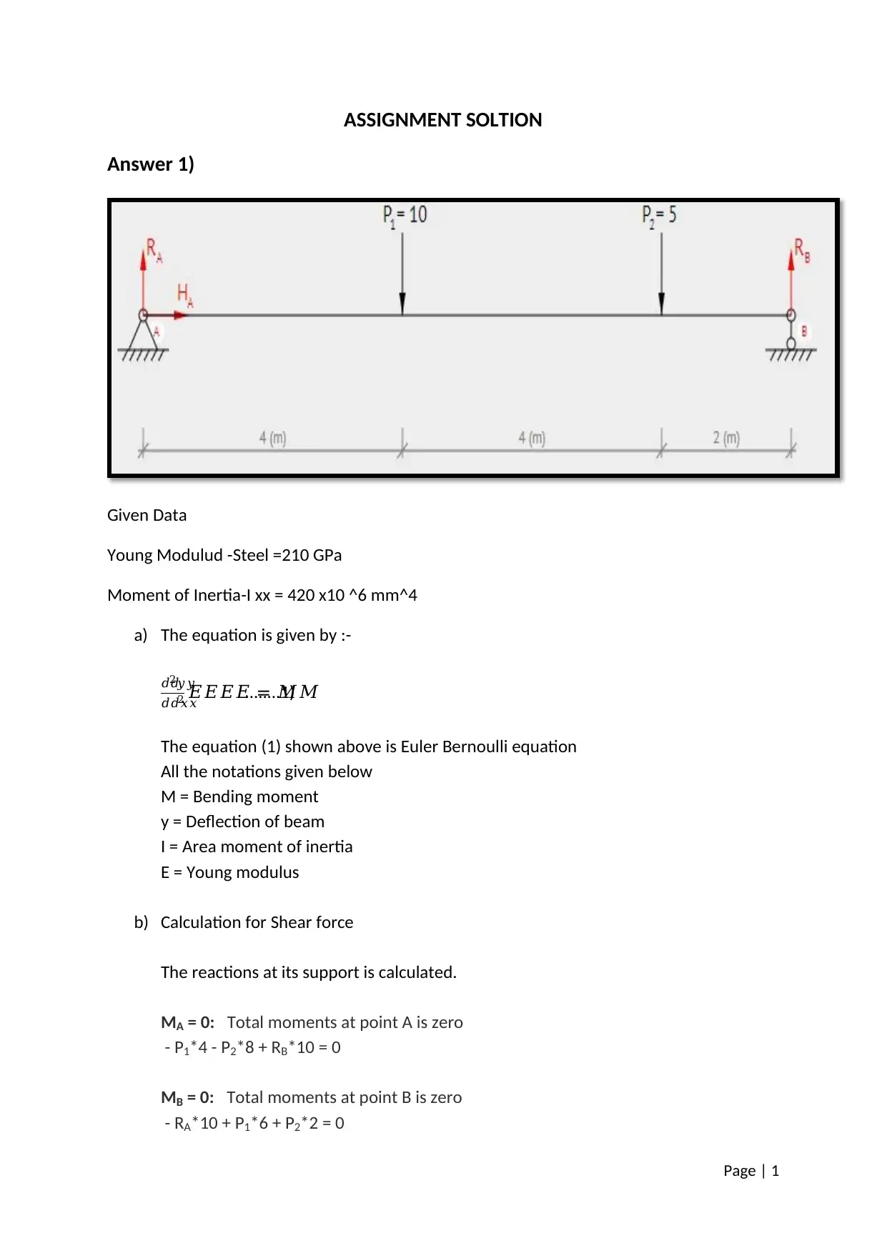
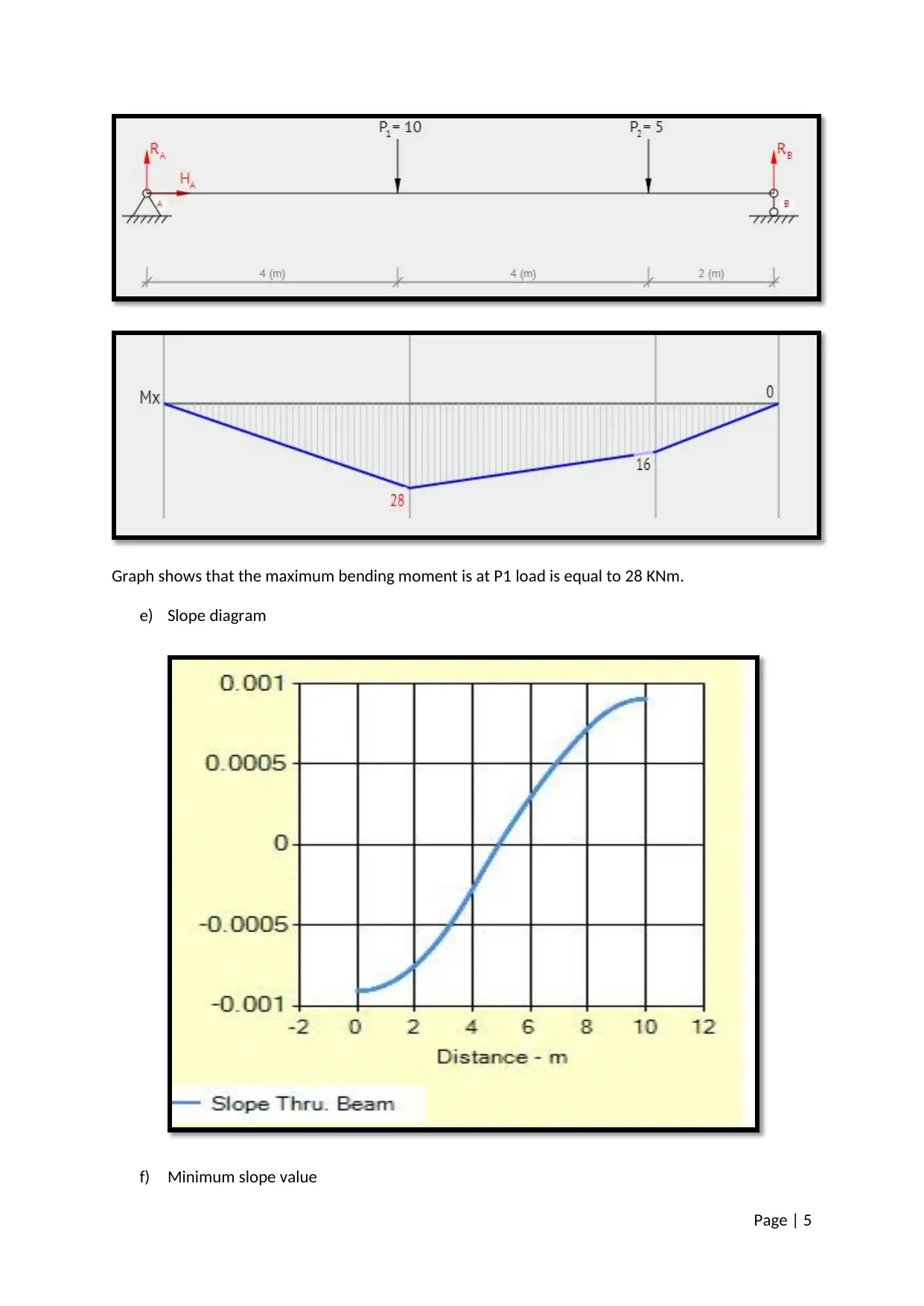
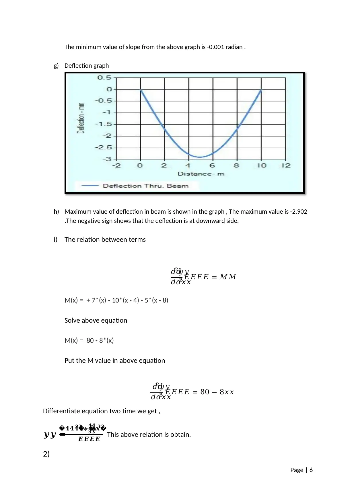
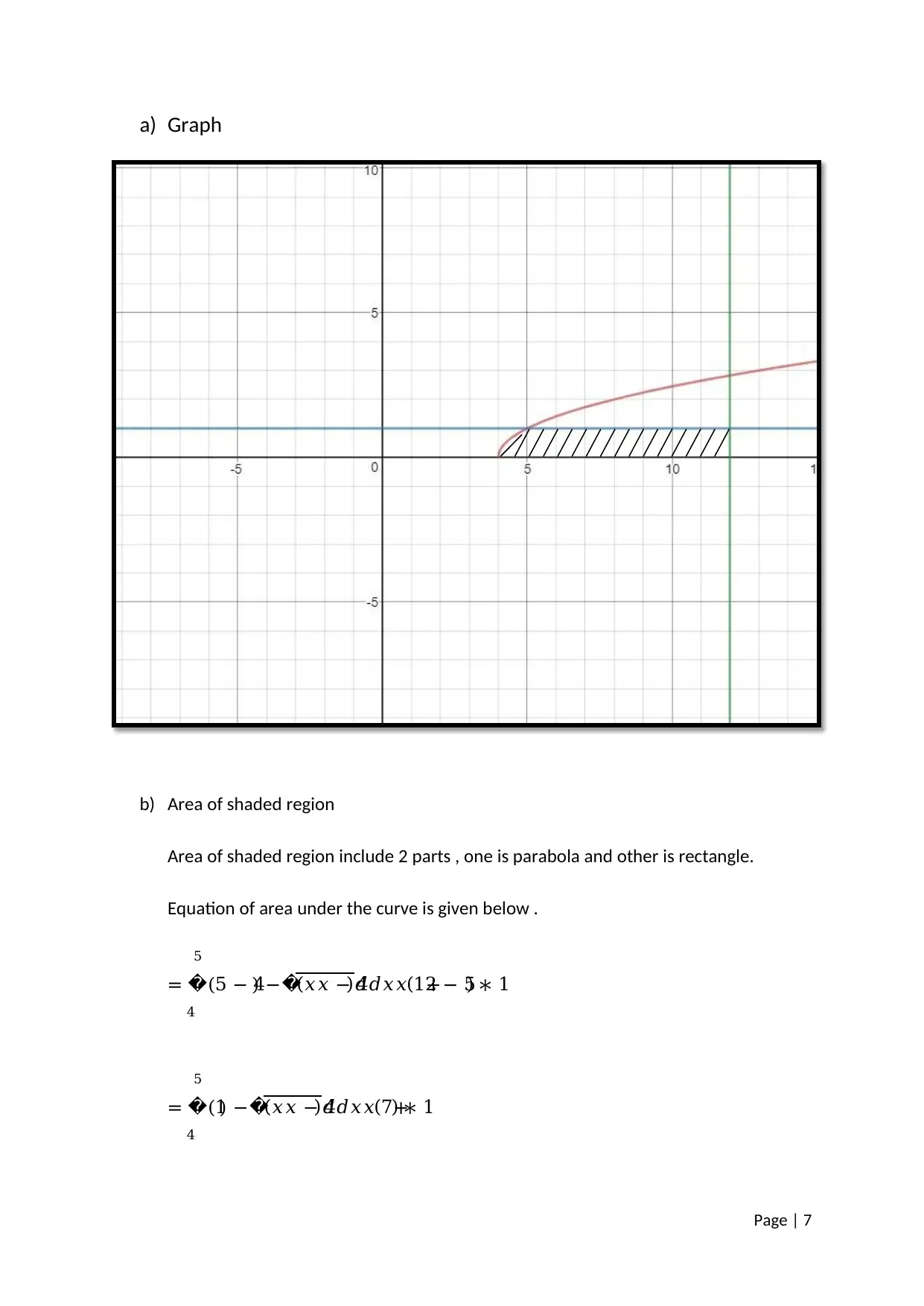
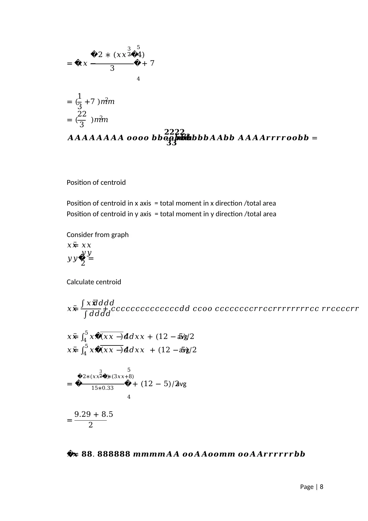
This assignment solution covers the analysis of beam deflection and stress, utilizing concepts such as Young's modulus, moment of inertia, shear force, and bending moment. The solution includes calculations for reactions at supports, shear force diagrams, bending moment diagrams, slope diagrams, and deflection graphs. It also addresses the determination of maximum shear force, maximum bending moment, minimum slope value, and maximum deflection. Furthermore, the assignment involves calculating the area of a shaded region, determining the position of the centroid, and finding the position of the center of gravity when the area revolves around its central axis. The solution employs the Euler-Bernoulli equation to relate bending moment to deflection and provides a step-by-step approach to solving related problems.

Page | 1
ASSIGNMENT SOLTION
Answer 1)
Given Data
Young Modulud -Steel =210 GPa
Moment of Inertia-I xx = 420 x10 ^6 mm^4
a) The equation is given by :-
ππ2π¦π¦
πππ₯π₯2 πΈπΈπΈπΈ = ππ........1)
The equation (1) shown above is Euler Bernoulli equation
All the notations given below
M = Bending moment
y = Deflection of beam
I = Area moment of inertia
E = Young modulus
b) Calculation for Shear force
The reactions at its support is calculated.
MA = 0: Total moments at point A is zero
- P1*4 - P2*8 + RB*10 = 0
MB = 0: Total moments at point B is zero
- RA*10 + P1*6 + P2*2 = 0
Paraphrase This Document
Need a fresh take? Get an instant paraphrase of this document with our AI Paraphraser

Page | 2
Solve equations
HA = 0 (kN)
Calculate reaction of roller support at point B
RB = ( P1*4 + P2*8) / 10 = ( 10*4 + 5*8) / 10 = 8.00 (kN)
Calculate reaction of pin support at point A
RA = ( P1*6 + P2*2) / 10 = ( 10*6 + 5*2) / 10 = 7.00 (kN)
First span of the beam: 0 β€ x1 < 4
Shear force (Q)
Q(x1) = + RA
Q1(0) = + 7 = 7 (kN)
Q1(4) = + 7 = 7 (kN)
Second span of the beam: 4 β€ x2 < 8
Shear force (Q)
Q(x2) = + RA - P1
Q2(4) = + 7 - 10 = -3 (kN)
Q2(8) = + 7 - 10 = -3 (kN)
Third span of the beam: 8 β€ x3 < 10
Determine the equations for the shear force (Q)
Q(x3) = + RA - P1 - P2
Q3(8) = + 7 - 10 - 5 = -8 (kN)
Q3(10) = + 7 - 10 - 5 = -8 (kN)

Page | 3
Graph shows that maximum shear force will be at location of P2 load of 8 KN .
c) Equation of bending moment
Bending moment (M)
M(x) = + RA*(x) - P1*(x - 4) - P2*(x - 8)
M(x) = + 7*(x) - 10*(x - 4) - 5*(x - 8)
d) Bending moment diagram
First span of the beam: 0 β€ x1 < 4
Graph shows that maximum shear force will be at location of P2 load of 8 KN .
c) Equation of bending moment
Bending moment (M)
M(x) = + RA*(x) - P1*(x - 4) - P2*(x - 8)
M(x) = + 7*(x) - 10*(x - 4) - 5*(x - 8)
d) Bending moment diagram
First span of the beam: 0 β€ x1 < 4
β This is a preview!β
Do you want full access?
Subscribe today to unlock all pages.

Trusted by 1+ million students worldwide

Page | 4
Bending moment (M)
M(x1) = + RA*(x1)
M1(0) = + 7*(0) = 0 (kN*m)
M1(4) = + 7*(4) = 28 (kN*m)
Second span of the beam: 4 β€ x2 < 8
Bending moment (M)
M(x2) = + RA*(x2) - P1*(x2 - 4)
M2(4) = + 7*(4) - 10*(4 - 4) = 28 (kN*m)
M2(8) = + 7*(8) - 10*(8 - 4) = 16 (kN*m)
Third span of the beam: 8 β€ x3 < 10
Bending moment (M)
M(x3) = + RA*(x3) - P1*(x3 - 4) - P2*(x3 - 8)
M3(8) = + 7*(8) - 10*(8 - 4) - 5*(8 - 8) = 16 (kN*m)
M3(10) = + 7*(10) - 10*(10 - 4) - 5*(10 - 8) = 0 (kN*m)
Bending moment (M)
M(x1) = + RA*(x1)
M1(0) = + 7*(0) = 0 (kN*m)
M1(4) = + 7*(4) = 28 (kN*m)
Second span of the beam: 4 β€ x2 < 8
Bending moment (M)
M(x2) = + RA*(x2) - P1*(x2 - 4)
M2(4) = + 7*(4) - 10*(4 - 4) = 28 (kN*m)
M2(8) = + 7*(8) - 10*(8 - 4) = 16 (kN*m)
Third span of the beam: 8 β€ x3 < 10
Bending moment (M)
M(x3) = + RA*(x3) - P1*(x3 - 4) - P2*(x3 - 8)
M3(8) = + 7*(8) - 10*(8 - 4) - 5*(8 - 8) = 16 (kN*m)
M3(10) = + 7*(10) - 10*(10 - 4) - 5*(10 - 8) = 0 (kN*m)
Paraphrase This Document
Need a fresh take? Get an instant paraphrase of this document with our AI Paraphraser

Page | 5
Graph shows that the maximum bending moment is at P1 load is equal to 28 KNm.
e) Slope diagram
f) Minimum slope value
Graph shows that the maximum bending moment is at P1 load is equal to 28 KNm.
e) Slope diagram
f) Minimum slope value

Page | 6
The minimum value of slope from the above graph is -0.001 radian .
g) Deflection graph
h) Maximum value of deflection in beam is shown in the graph , The maximum value is -2.902
.The negative sign shows that the deflection is at downward side.
i) The relation between terms
ππ2π¦π¦
πππ₯π₯2 πΈπΈπΈπΈ = ππ
M(x) = + 7*(x) - 10*(x - 4) - 5*(x - 8)
Solve above equation
M(x) = 80 - 8*(x)
Put the M value in above equation
ππ2π¦π¦
πππ₯π₯2 πΈπΈπΈπΈ = 80 β 8π₯π₯
Differentiate equation two time we get ,
ππ =ππππβπποΏ½ ππ βοΏ½ οΏ½
ππ
ππ
βπππποΏ½
π¬π¬π¬π¬ This above relation is obtain.
2)
β This is a preview!β
Do you want full access?
Subscribe today to unlock all pages.

Trusted by 1+ million students worldwide

Page | 7
a) Graph
b) Area of shaded region
Area of shaded region include 2 parts , one is parabola and other is rectangle.
Equation of area under the curve is given below .
= (5 β 4οΏ½
5
4
) βοΏ½(π₯π₯ β 4)πππ₯π₯ +(12 β 5) β 1
= (1οΏ½
5
4
) βοΏ½(π₯π₯ β 4)πππ₯π₯ +(7) β 1
a) Graph
b) Area of shaded region
Area of shaded region include 2 parts , one is parabola and other is rectangle.
Equation of area under the curve is given below .
= (5 β 4οΏ½
5
4
) βοΏ½(π₯π₯ β 4)πππ₯π₯ +(12 β 5) β 1
= (1οΏ½
5
4
) βοΏ½(π₯π₯ β 4)πππ₯π₯ +(7) β 1
Paraphrase This Document
Need a fresh take? Get an instant paraphrase of this document with our AI Paraphraser

Page | 8
= οΏ½π₯π₯ β
οΏ½2 β (π₯π₯ β 4)
3
2οΏ½
3 οΏ½
4
5
+ 7
= (1
3 +7 )ππ2
= (22
3 )ππ2
π¨π¨π¨π¨π¨π¨π¨π¨ ππππ πππππππππππ¨π¨ππ π¨π¨π¨π¨ππππππππ =
ππππ
ππππππ
Position of centroid
Position of centroid in x axis = total moment in x direction /total area
Position of centroid in y axis = total moment in y direction /total area
Consider from graph
π₯π₯Μ = π₯π₯
π¦π¦οΏ½ =
π¦π¦
2
Calculate centroid
π₯π₯Μ = β« π₯π₯Μ ππππ
β« ππππ
+ ππππππππππππππππ ππππ ππππππππππππππππππππππ ππππππππ
π₯π₯Μ = β« π₯π₯
5
4 οΏ½(π₯π₯ β 4)πππ₯π₯ + (12 β 5)/2avg
π₯π₯Μ = β« π₯π₯
5
4 οΏ½(π₯π₯ β 4)πππ₯π₯ + (12 β 5)/2avg
= οΏ½
οΏ½2β(π₯π₯β4)
3
2 βοΏ½ (3π₯π₯+8)
15β0.33 οΏ½
4
5
+ (12 β 5)/2avg
= 9.29 + 8.5
2
πποΏ½= ππ. ππππππ πππππ¨π¨ πππ¨π¨ππππ πππ¨π¨ππππππππ

Page | 9
Similarly calculated for y and obtain
π¦π¦οΏ½ =
β« π¦π¦ πππποΏ½
β« ππππ
π¦π¦οΏ½ = οΏ½
π¦π¦
2
5
4
οΏ½(π₯π₯ β 4)πππ₯π₯
πποΏ½= ππ. ππππππ πππππ¨π¨ πππ¨π¨ππππ πππ¨π¨ππππππππ
c) Position of center of gravity when area revolve around its central axis .
Center of gravity is the sum of all the moment to the total weight of body.
Center of gravity will be similar to point of centroid so center of gravity will be
πποΏ½= ππ. ππππππ πππππ¨π¨ πππ¨π¨ππππ πππ¨π¨ππππππππ
β This is a preview!β
Do you want full access?
Subscribe today to unlock all pages.

Trusted by 1+ million students worldwide
1 out of 9
Related Documents

Your All-in-One AI-Powered Toolkit for Academic Success.
Β +13062052269
info@desklib.com
Available 24*7 on WhatsApp / Email
Unlock your academic potential
Copyright Β© 2020β2025 A2Z Services. All Rights Reserved. Developed and managed by ZUCOL.