Bearing Assembly Design and Operation of Sustainable Systems Report
VerifiedAdded on 2023/04/10
|18
|3328
|195
Report
AI Summary
This report presents a detailed analysis of bearing assembly design for sustainable systems, focusing on minimizing power loss. The report begins with an introduction to solar central receiver systems and the importance of bearing design in heliostats. It then delves into the selection of bearing diameter, considering factors like diametral clearance, radial clearance, and eccentricity. The report includes calculations for the bearing diameter, taking into account the l/d ratio and the Sommerfeld Number. Furthermore, it analyzes pressure, forces, and the selection of the bearing diameter, considering the load exerted by the heliostat. The report also examines the PV value, max specific wear rate, and material selection, including useful life calculations. It discusses wear mechanisms and material properties, such as compressive strength, thermal expansion, and heat conductivity. The final section recommends Tin base Babbit as a suitable material and references relevant figures and tables to support the analysis.
1
Design and Operation of Sustainable Systems
Name
Class (Course)
Professor (Tutor)
School (University)
The City and State
The Date
Design and Operation of Sustainable Systems
Name
Class (Course)
Professor (Tutor)
School (University)
The City and State
The Date
Paraphrase This Document
Need a fresh take? Get an instant paraphrase of this document with our AI Paraphraser
2
1. Introduction
A sun oriented focal recipient involves the utilization of a field of mirrors called heliostats
which are coordinated towards a collector which is at the highest point of a tower (Ho et al.
2017). The heliostats behave like an expansive allegorical reflector divided into little
portions. The recipient warms up in light of the approaching sun powered radiation liquid and
transmits warmth to a warmth exchange liquid which used to run a turbine. The idea of
sunlight based focal collector control plants exuded in Sandia National Laboratories in 1976
with the foundation of the National Solar Thermal Test Facility in Albuquerque, New
Mexico. From that point forward, a few pilot plant have been built worldwide with the
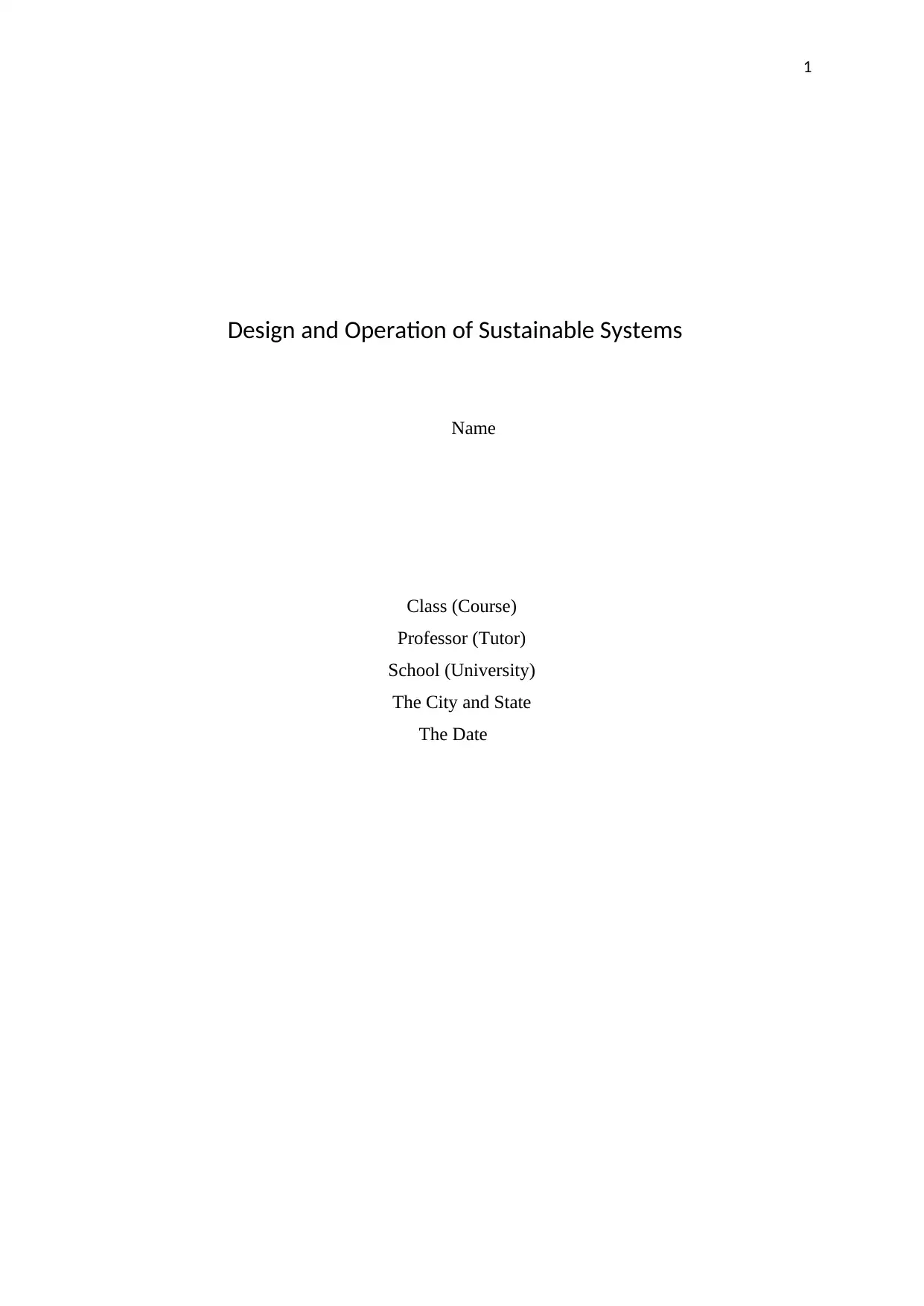
biggest one being the Solar One plant in Barstow, California. According to Ho et al. (2017),
Solar One covered an area of 72 acres of land with a reflective area of 39.9 m2 square meters
provided by each of the 1818 heliostats and produced 10MW of power it worked from 1982
to 1988 when Solar Two was built
Figure 1: Solar One. Source: (Ho et al. 2017)
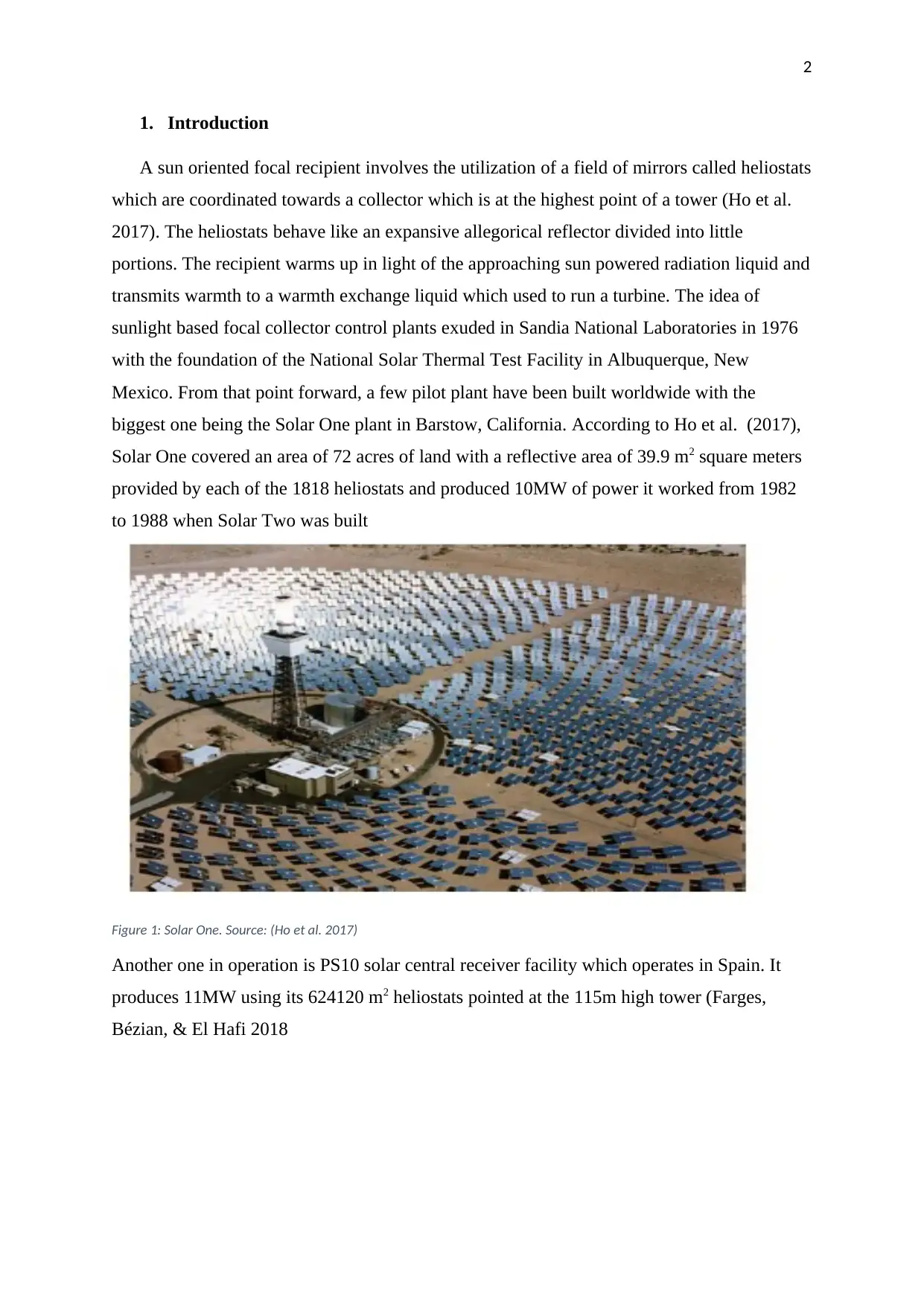
Another one in operation is PS10 solar central receiver facility which operates in Spain. It
produces 11MW using its 624120 m2 heliostats pointed at the 115m high tower (Farges,
Bézian, & El Hafi 2018
1. Introduction
A sun oriented focal recipient involves the utilization of a field of mirrors called heliostats
which are coordinated towards a collector which is at the highest point of a tower (Ho et al.
2017). The heliostats behave like an expansive allegorical reflector divided into little
portions. The recipient warms up in light of the approaching sun powered radiation liquid and
transmits warmth to a warmth exchange liquid which used to run a turbine. The idea of
sunlight based focal collector control plants exuded in Sandia National Laboratories in 1976
with the foundation of the National Solar Thermal Test Facility in Albuquerque, New
Mexico. From that point forward, a few pilot plant have been built worldwide with the
biggest one being the Solar One plant in Barstow, California. According to Ho et al. (2017),
Solar One covered an area of 72 acres of land with a reflective area of 39.9 m2 square meters
provided by each of the 1818 heliostats and produced 10MW of power it worked from 1982
to 1988 when Solar Two was built
Figure 1: Solar One. Source: (Ho et al. 2017)
Another one in operation is PS10 solar central receiver facility which operates in Spain. It
produces 11MW using its 624120 m2 heliostats pointed at the 115m high tower (Farges,
Bézian, & El Hafi 2018
3
Figure 2:PS10 heliostat, Spain. Source: (Farges, Bézian, & El Hafi, 2018)
The main components of the power plants include the turbine, the tower, the receiver, and
heliostats. From these designs above, the mirrors are large and hence, difficult in cleaning,
and need a large land area to avoid shadowing and blocking. As compared to the proposed
design, they are more prone to wind load which can cause increased spillage in the receiver.
2. Selection of bearing diameter.
There is a desire to minimize the maintenance actions by with the trade-off with the size
of the bearing. The consideration is that the bearing should be big enough to last 25 years and
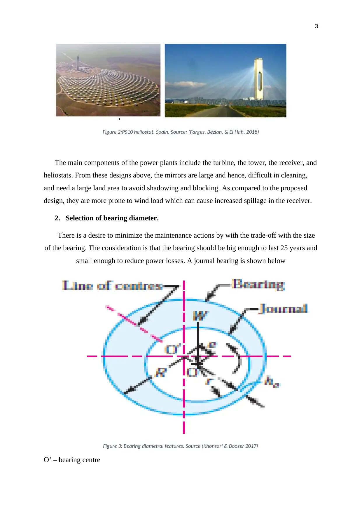
small enough to reduce power losses. A journal bearing is shown below
Figure 3: Bearing diametral features. Source (Khonsari & Booser 2017)
O’ – bearing centre
Figure 2:PS10 heliostat, Spain. Source: (Farges, Bézian, & El Hafi, 2018)
The main components of the power plants include the turbine, the tower, the receiver, and
heliostats. From these designs above, the mirrors are large and hence, difficult in cleaning,
and need a large land area to avoid shadowing and blocking. As compared to the proposed
design, they are more prone to wind load which can cause increased spillage in the receiver.
2. Selection of bearing diameter.
There is a desire to minimize the maintenance actions by with the trade-off with the size
of the bearing. The consideration is that the bearing should be big enough to last 25 years and
small enough to reduce power losses. A journal bearing is shown below
Figure 3: Bearing diametral features. Source (Khonsari & Booser 2017)
O’ – bearing centre
⊘ This is a preview!⊘
Do you want full access?
Subscribe today to unlock all pages.
Trusted by 1+ million students worldwide
4
O – journal centre
I – bearing length
d- journal diameter
D – bearing diameter
The key terms to consider in this case include
Diametral clearance which is the difference between the diameters of the journal and the
bearing. This can be calculated from the formula
c = D – d
The bearing’s diametric clearance, c, ought to be little enough to create the essential
speed inclinations with the goal that the weight develop will bolster the heap. Likewise, the
little freedom has favorable position of diminishing the side spillages (Khonsari & Booser
2017). In any case, the recompense should be made for assembling resistance in this diary
and bushing. The ordinarily utilized leeway in mechanical machines is 0.025mm per cm of
journal diameter.
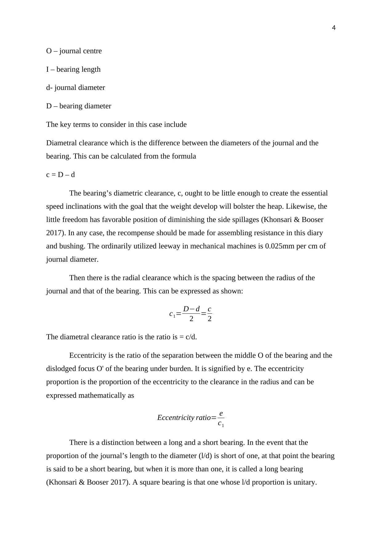
Then there is the radial clearance which is the spacing between the radius of the
journal and that of the bearing. This can be expressed as shown:
c1= D−d
2 = c
2
The diametral clearance ratio is the ratio is = c/d.
Eccentricity is the ratio of the separation between the middle O of the bearing and the
dislodged focus O' of the bearing under burden. It is signified by e. The eccentricity
proportion is the proportion of the eccentricity to the clearance in the radius and can be
expressed mathematically as
Eccentricity ratio= e
c1
There is a distinction between a long and a short bearing. In the event that the
proportion of the journal’s length to the diameter (l/d) is short of one, at that point the bearing
is said to be a short bearing, but when it is more than one, it is called a long bearing
(Khonsari & Booser 2017). A square bearing is that one whose l/d proportion is unitary.
O – journal centre
I – bearing length
d- journal diameter
D – bearing diameter
The key terms to consider in this case include
Diametral clearance which is the difference between the diameters of the journal and the
bearing. This can be calculated from the formula
c = D – d
The bearing’s diametric clearance, c, ought to be little enough to create the essential
speed inclinations with the goal that the weight develop will bolster the heap. Likewise, the
little freedom has favorable position of diminishing the side spillages (Khonsari & Booser
2017). In any case, the recompense should be made for assembling resistance in this diary
and bushing. The ordinarily utilized leeway in mechanical machines is 0.025mm per cm of
journal diameter.
Then there is the radial clearance which is the spacing between the radius of the
journal and that of the bearing. This can be expressed as shown:
c1= D−d
2 = c
2
The diametral clearance ratio is the ratio is = c/d.
Eccentricity is the ratio of the separation between the middle O of the bearing and the
dislodged focus O' of the bearing under burden. It is signified by e. The eccentricity
proportion is the proportion of the eccentricity to the clearance in the radius and can be
expressed mathematically as
Eccentricity ratio= e
c1
There is a distinction between a long and a short bearing. In the event that the
proportion of the journal’s length to the diameter (l/d) is short of one, at that point the bearing
is said to be a short bearing, but when it is more than one, it is called a long bearing
(Khonsari & Booser 2017). A square bearing is that one whose l/d proportion is unitary.
Paraphrase This Document
Need a fresh take? Get an instant paraphrase of this document with our AI Paraphraser
5
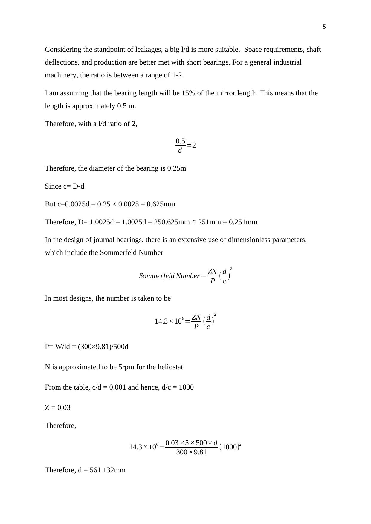
Considering the standpoint of leakages, a big l/d is more suitable. Space requirements, shaft
deflections, and production are better met with short bearings. For a general industrial
machinery, the ratio is between a range of 1-2.
I am assuming that the bearing length will be 15% of the mirror length. This means that the
length is approximately 0.5 m.
Therefore, with a l/d ratio of 2,
0.5
d =2
Therefore, the diameter of the bearing is 0.25m
Since c= D-d
But c=0.0025d = 0.25 × 0.0025 = 0.625mm
Therefore, D= 1.0025d = 1.0025d = 250.625mm ≅ 251mm = 0.251mm
In the design of journal bearings, there is an extensive use of dimensionless parameters,
which include the Sommerfeld Number
Sommerfeld Number = ZN
P ( d
c )
2
In most designs, the number is taken to be
14.3 ×106 = ZN
P ( d
c )
2
P= W/ld = (300×9.81)/500d
N is approximated to be 5rpm for the heliostat
From the table, c/d = 0.001 and hence, d/c = 1000
Z = 0.03
Therefore,
14.3 ×106 =0.03 ×5 × 500× d
300 ×9.81 (1000)2
Therefore, d = 561.132mm
6
Since c/d =0.001 = (D-d)/d
D = 561.692, say 562mm
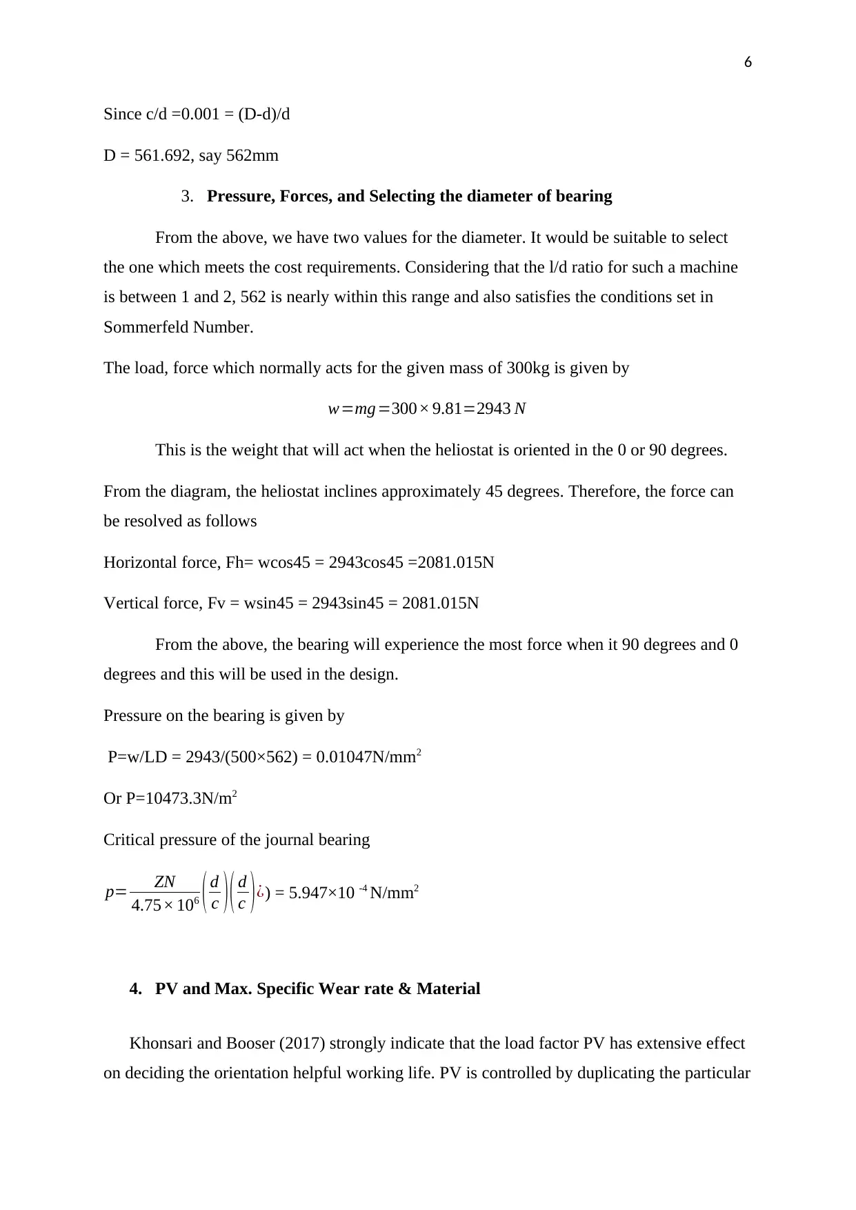
3. Pressure, Forces, and Selecting the diameter of bearing
From the above, we have two values for the diameter. It would be suitable to select
the one which meets the cost requirements. Considering that the l/d ratio for such a machine
is between 1 and 2, 562 is nearly within this range and also satisfies the conditions set in
Sommerfeld Number.
The load, force which normally acts for the given mass of 300kg is given by
w=mg=300× 9.81=2943 N
This is the weight that will act when the heliostat is oriented in the 0 or 90 degrees.
From the diagram, the heliostat inclines approximately 45 degrees. Therefore, the force can
be resolved as follows
Horizontal force, Fh= wcos45 = 2943cos45 =2081.015N
Vertical force, Fv = wsin45 = 2943sin45 = 2081.015N
From the above, the bearing will experience the most force when it 90 degrees and 0
degrees and this will be used in the design.
Pressure on the bearing is given by
P=w/LD = 2943/(500×562) = 0.01047N/mm2
Or P=10473.3N/m2
Critical pressure of the journal bearing
p= ZN
4.75× 10⁶ ( d
c )( d
c )¿) = 5.947×10 -4 N/mm2
4. PV and Max. Specific Wear rate & Material
Khonsari and Booser (2017) strongly indicate that the load factor PV has extensive effect
on deciding the orientation helpful working life. PV is controlled by duplicating the particular
Since c/d =0.001 = (D-d)/d
D = 561.692, say 562mm
3. Pressure, Forces, and Selecting the diameter of bearing
From the above, we have two values for the diameter. It would be suitable to select
the one which meets the cost requirements. Considering that the l/d ratio for such a machine
is between 1 and 2, 562 is nearly within this range and also satisfies the conditions set in
Sommerfeld Number.
The load, force which normally acts for the given mass of 300kg is given by
w=mg=300× 9.81=2943 N
This is the weight that will act when the heliostat is oriented in the 0 or 90 degrees.
From the diagram, the heliostat inclines approximately 45 degrees. Therefore, the force can
be resolved as follows
Horizontal force, Fh= wcos45 = 2943cos45 =2081.015N
Vertical force, Fv = wsin45 = 2943sin45 = 2081.015N
From the above, the bearing will experience the most force when it 90 degrees and 0
degrees and this will be used in the design.
Pressure on the bearing is given by
P=w/LD = 2943/(500×562) = 0.01047N/mm2
Or P=10473.3N/m2
Critical pressure of the journal bearing
p= ZN
4.75× 10⁶ ( d
c )( d
c )¿) = 5.947×10 -4 N/mm2
4. PV and Max. Specific Wear rate & Material
Khonsari and Booser (2017) strongly indicate that the load factor PV has extensive effect
on deciding the orientation helpful working life. PV is controlled by duplicating the particular
⊘ This is a preview!⊘
Do you want full access?
Subscribe today to unlock all pages.
Trusted by 1+ million students worldwide
7
bearing burden or pressure(p) by the sliding velocity (v). Bearing materials are appraised by a
PV limit, with as far as possible speaking to the most elevated blend of burden and speed
under which the bearing material will work. The PV unit of measure is N/mm² x m/s.
To decide P in an application: the particular bearing burden (P) is dictated by separating
the bearing burden by the weight supporting are of the bearing (Khonsari & Booser 2017).
The units for P are N/mm². The weight supporting zone relies upon the particular geometry of
the bearing.
P =0.01047N/mm2
V = πd ∂ Nos
60 ×103 ×360 =6.130× 10⁻⁵ m/ s
Where d is inside diameter, Nos is the frequency of oscillations in cycles per minute
(Assuming an average of 1.666 cycles per minute, N is rpm, ∂ is the angle of oscillation in
degrees, and v is the sliding speed
Therefore, PV = 0.01047×6.130 × 10−4 = 6.418 ×10⁻⁴ N /mms
The wear coefficient k, is the ratio of lost volume to sliding distance and load applied.
k =ΔV/P·L
In this case, v = lπ (d2 – (d-12)2)/4 = 500×3.142 (5622 – (562-12)2)/4= 9520596.53mm3
k= 6469 mm3/ Nm
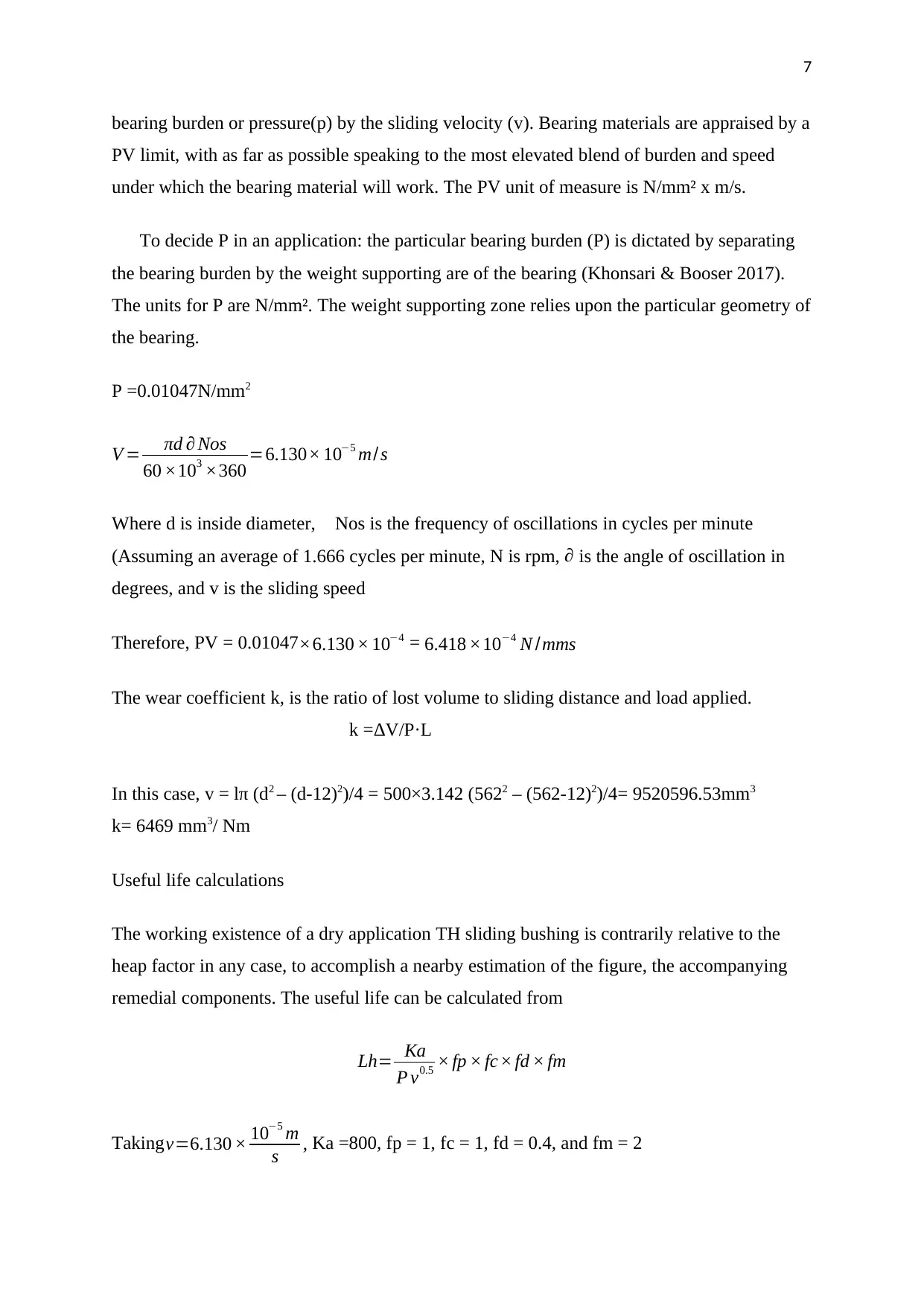
Useful life calculations
The working existence of a dry application TH sliding bushing is contrarily relative to the
heap factor in any case, to accomplish a nearby estimation of the figure, the accompanying
remedial components. The useful life can be calculated from
Lh= Ka
P v0.5 × fp × fc× fd × fm
Takingv=6.130 × 10⁻⁵ m
s , Ka =800, fp = 1, fc = 1, fd = 0.4, and fm = 2
bearing burden or pressure(p) by the sliding velocity (v). Bearing materials are appraised by a
PV limit, with as far as possible speaking to the most elevated blend of burden and speed
under which the bearing material will work. The PV unit of measure is N/mm² x m/s.
To decide P in an application: the particular bearing burden (P) is dictated by separating
the bearing burden by the weight supporting are of the bearing (Khonsari & Booser 2017).
The units for P are N/mm². The weight supporting zone relies upon the particular geometry of
the bearing.
P =0.01047N/mm2
V = πd ∂ Nos
60 ×103 ×360 =6.130× 10⁻⁵ m/ s
Where d is inside diameter, Nos is the frequency of oscillations in cycles per minute
(Assuming an average of 1.666 cycles per minute, N is rpm, ∂ is the angle of oscillation in
degrees, and v is the sliding speed
Therefore, PV = 0.01047×6.130 × 10−4 = 6.418 ×10⁻⁴ N /mms
The wear coefficient k, is the ratio of lost volume to sliding distance and load applied.
k =ΔV/P·L
In this case, v = lπ (d2 – (d-12)2)/4 = 500×3.142 (5622 – (562-12)2)/4= 9520596.53mm3
k= 6469 mm3/ Nm
Useful life calculations
The working existence of a dry application TH sliding bushing is contrarily relative to the
heap factor in any case, to accomplish a nearby estimation of the figure, the accompanying
remedial components. The useful life can be calculated from
Lh= Ka
P v0.5 × fp × fc× fd × fm
Takingv=6.130 × 10⁻⁵ m
s , Ka =800, fp = 1, fc = 1, fd = 0.4, and fm = 2
Paraphrase This Document
Need a fresh take? Get an instant paraphrase of this document with our AI Paraphraser
8
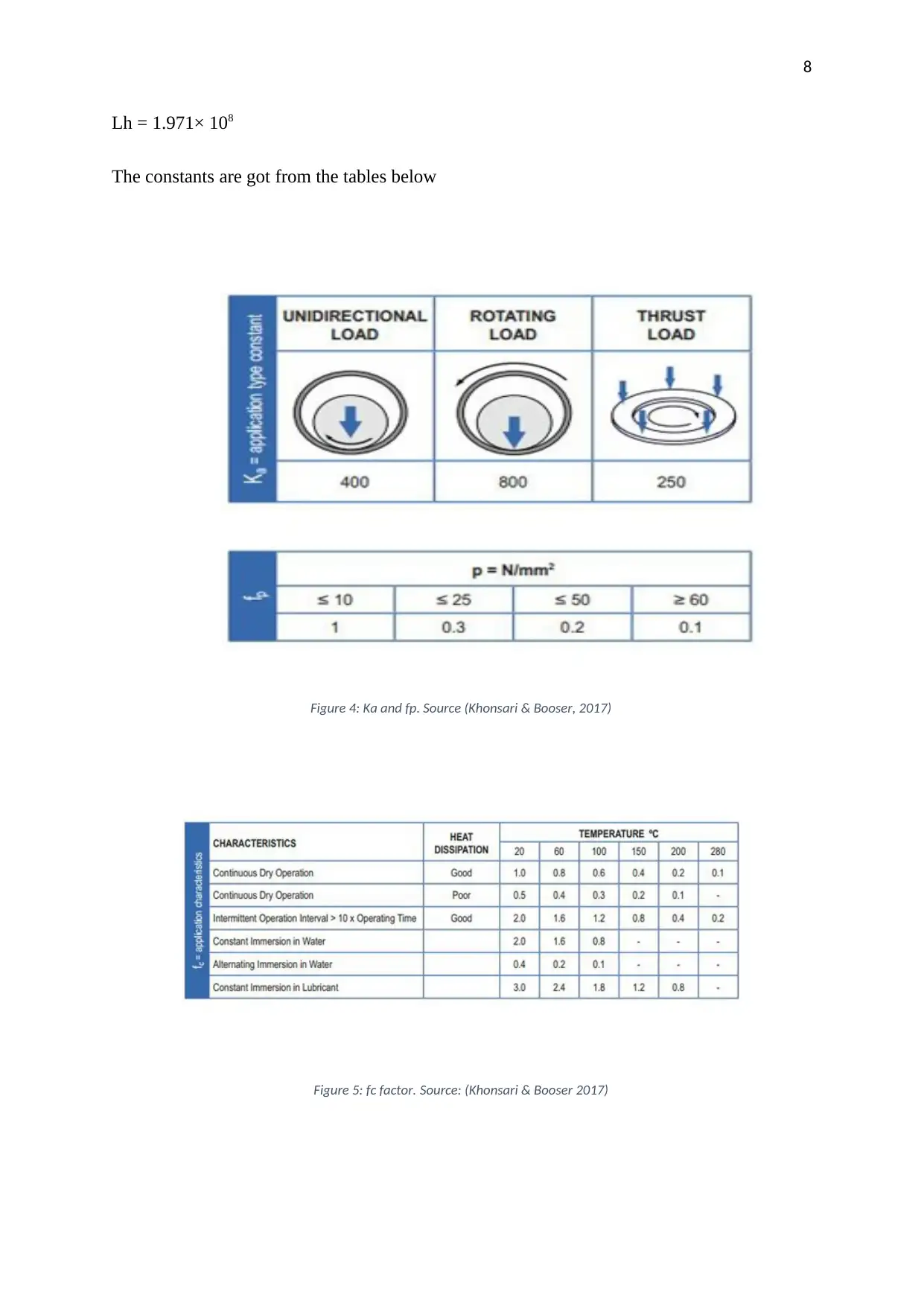
Lh = 1.971× 10⁸
The constants are got from the tables below
Figure 4: Ka and fp. Source (Khonsari & Booser, 2017)
Figure 5: fc factor. Source: (Khonsari & Booser 2017)
Lh = 1.971× 10⁸
The constants are got from the tables below
Figure 4: Ka and fp. Source (Khonsari & Booser, 2017)
Figure 5: fc factor. Source: (Khonsari & Booser 2017)
9
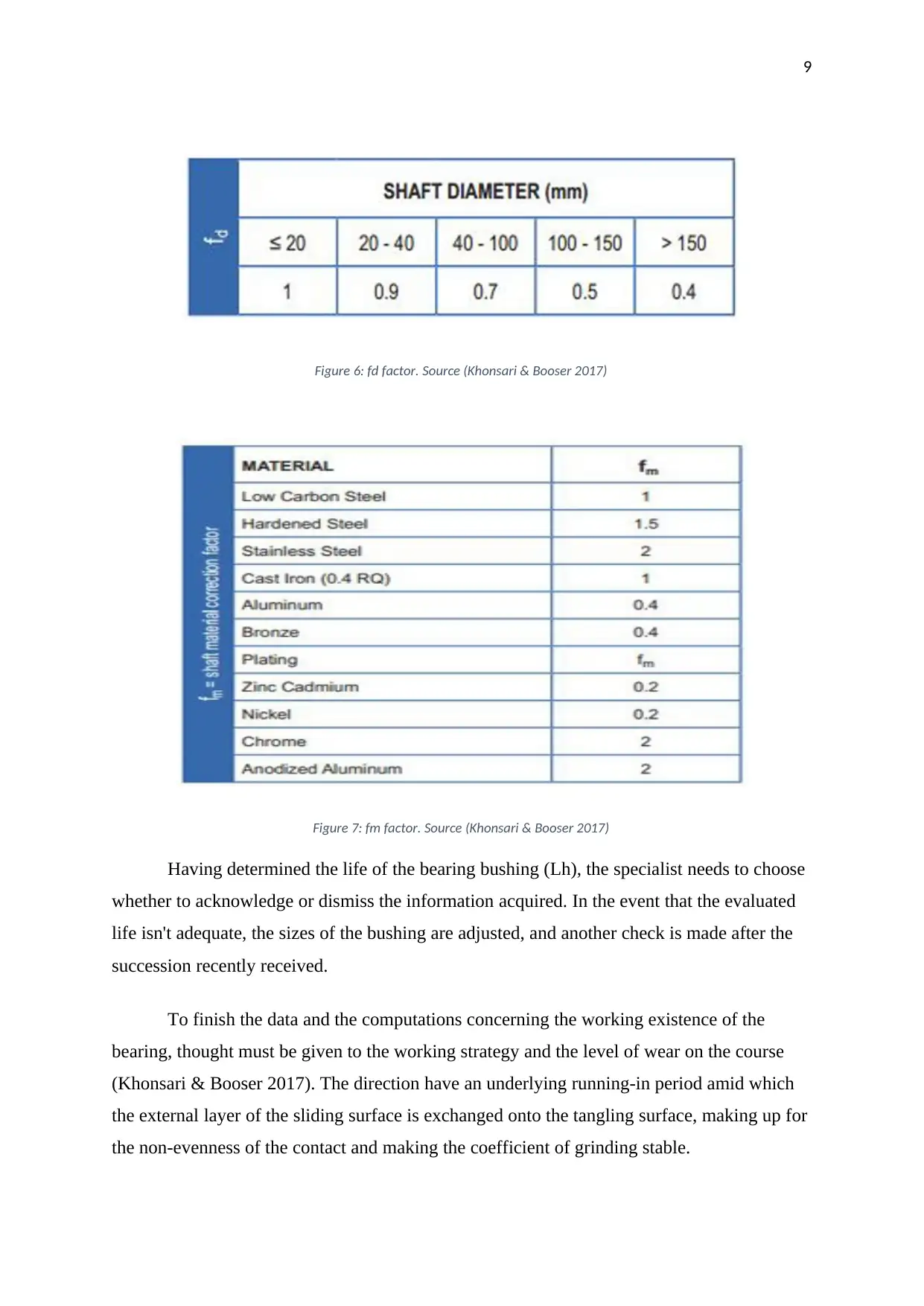
Figure 6: fd factor. Source (Khonsari & Booser 2017)
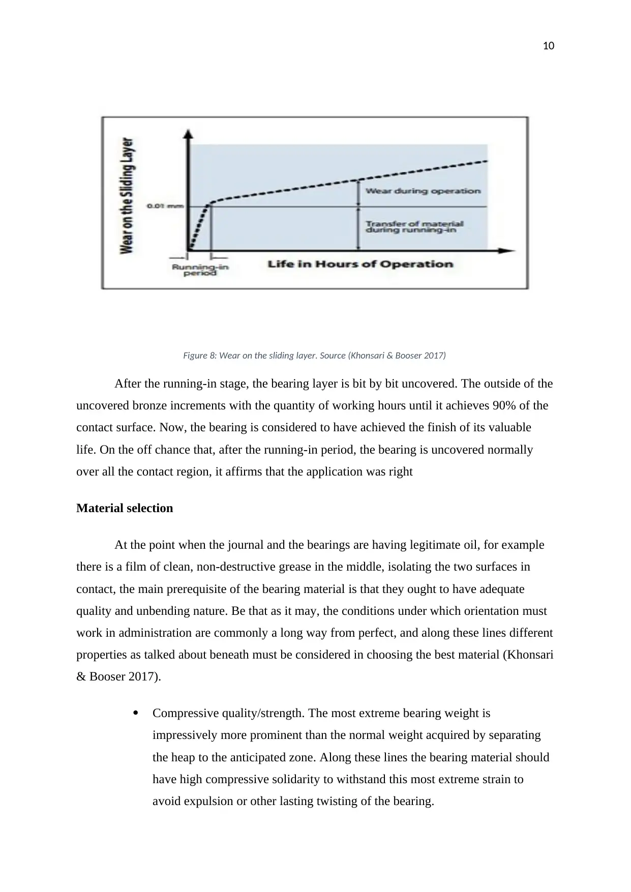
Figure 7: fm factor. Source (Khonsari & Booser 2017)
Having determined the life of the bearing bushing (Lh), the specialist needs to choose
whether to acknowledge or dismiss the information acquired. In the event that the evaluated
life isn't adequate, the sizes of the bushing are adjusted, and another check is made after the
succession recently received.
To finish the data and the computations concerning the working existence of the
bearing, thought must be given to the working strategy and the level of wear on the course
(Khonsari & Booser 2017). The direction have an underlying running-in period amid which
the external layer of the sliding surface is exchanged onto the tangling surface, making up for
the non-evenness of the contact and making the coefficient of grinding stable.
Figure 6: fd factor. Source (Khonsari & Booser 2017)
Figure 7: fm factor. Source (Khonsari & Booser 2017)
Having determined the life of the bearing bushing (Lh), the specialist needs to choose
whether to acknowledge or dismiss the information acquired. In the event that the evaluated
life isn't adequate, the sizes of the bushing are adjusted, and another check is made after the
succession recently received.
To finish the data and the computations concerning the working existence of the
bearing, thought must be given to the working strategy and the level of wear on the course
(Khonsari & Booser 2017). The direction have an underlying running-in period amid which
the external layer of the sliding surface is exchanged onto the tangling surface, making up for
the non-evenness of the contact and making the coefficient of grinding stable.
⊘ This is a preview!⊘
Do you want full access?
Subscribe today to unlock all pages.
Trusted by 1+ million students worldwide
10
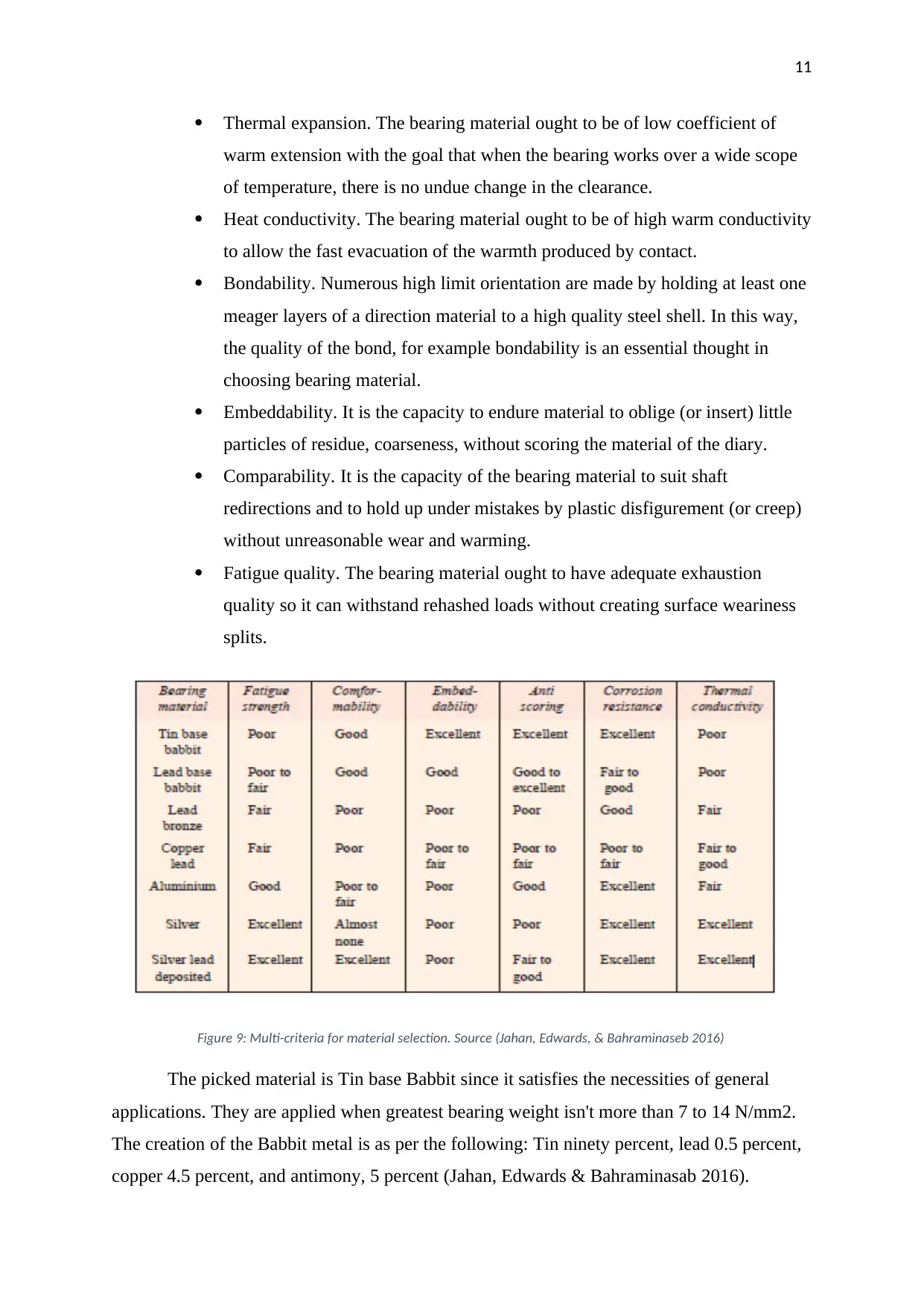
Figure 8: Wear on the sliding layer. Source (Khonsari & Booser 2017)
After the running-in stage, the bearing layer is bit by bit uncovered. The outside of the
uncovered bronze increments with the quantity of working hours until it achieves 90% of the
contact surface. Now, the bearing is considered to have achieved the finish of its valuable
life. On the off chance that, after the running-in period, the bearing is uncovered normally
over all the contact region, it affirms that the application was right
Material selection
At the point when the journal and the bearings are having legitimate oil, for example
there is a film of clean, non-destructive grease in the middle, isolating the two surfaces in
contact, the main prerequisite of the bearing material is that they ought to have adequate
quality and unbending nature. Be that as it may, the conditions under which orientation must
work in administration are commonly a long way from perfect, and along these lines different
properties as talked about beneath must be considered in choosing the best material (Khonsari
& Booser 2017).
Compressive quality/strength. The most extreme bearing weight is
impressively more prominent than the normal weight acquired by separating
the heap to the anticipated zone. Along these lines the bearing material should
have high compressive solidarity to withstand this most extreme strain to
avoid expulsion or other lasting twisting of the bearing.
Paraphrase This Document
Need a fresh take? Get an instant paraphrase of this document with our AI Paraphraser
11
Thermal expansion. The bearing material ought to be of low coefficient of
warm extension with the goal that when the bearing works over a wide scope
of temperature, there is no undue change in the clearance.
Heat conductivity. The bearing material ought to be of high warm conductivity
to allow the fast evacuation of the warmth produced by contact.
Bondability. Numerous high limit orientation are made by holding at least one
meager layers of a direction material to a high quality steel shell. In this way,
the quality of the bond, for example bondability is an essential thought in
choosing bearing material.
Embeddability. It is the capacity to endure material to oblige (or insert) little
particles of residue, coarseness, without scoring the material of the diary.
Comparability. It is the capacity of the bearing material to suit shaft
redirections and to hold up under mistakes by plastic disfigurement (or creep)
without unreasonable wear and warming.
Fatigue quality. The bearing material ought to have adequate exhaustion
quality so it can withstand rehashed loads without creating surface weariness
splits.
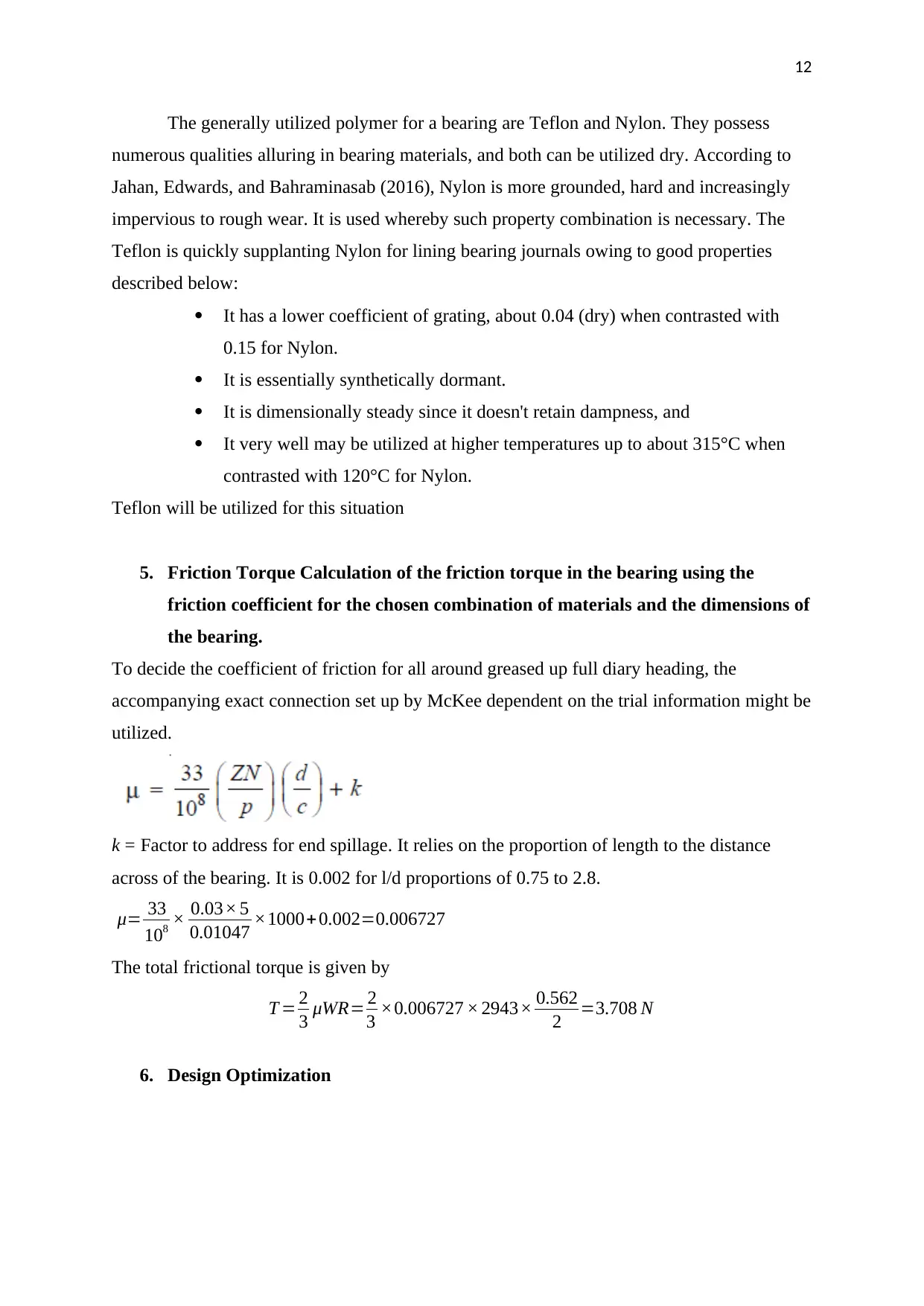
Figure 9: Multi-criteria for material selection. Source (Jahan, Edwards, & Bahraminaseb 2016)
The picked material is Tin base Babbit since it satisfies the necessities of general
applications. They are applied when greatest bearing weight isn't more than 7 to 14 N/mm2.
The creation of the Babbit metal is as per the following: Tin ninety percent, lead 0.5 percent,
copper 4.5 percent, and antimony, 5 percent (Jahan, Edwards & Bahraminasab 2016).
Thermal expansion. The bearing material ought to be of low coefficient of
warm extension with the goal that when the bearing works over a wide scope
of temperature, there is no undue change in the clearance.
Heat conductivity. The bearing material ought to be of high warm conductivity
to allow the fast evacuation of the warmth produced by contact.
Bondability. Numerous high limit orientation are made by holding at least one
meager layers of a direction material to a high quality steel shell. In this way,
the quality of the bond, for example bondability is an essential thought in
choosing bearing material.
Embeddability. It is the capacity to endure material to oblige (or insert) little
particles of residue, coarseness, without scoring the material of the diary.
Comparability. It is the capacity of the bearing material to suit shaft
redirections and to hold up under mistakes by plastic disfigurement (or creep)
without unreasonable wear and warming.
Fatigue quality. The bearing material ought to have adequate exhaustion
quality so it can withstand rehashed loads without creating surface weariness
splits.
Figure 9: Multi-criteria for material selection. Source (Jahan, Edwards, & Bahraminaseb 2016)
The picked material is Tin base Babbit since it satisfies the necessities of general
applications. They are applied when greatest bearing weight isn't more than 7 to 14 N/mm2.
The creation of the Babbit metal is as per the following: Tin ninety percent, lead 0.5 percent,
copper 4.5 percent, and antimony, 5 percent (Jahan, Edwards & Bahraminasab 2016).
12
The generally utilized polymer for a bearing are Teflon and Nylon. They possess
numerous qualities alluring in bearing materials, and both can be utilized dry. According to
Jahan, Edwards, and Bahraminasab (2016), Nylon is more grounded, hard and increasingly
impervious to rough wear. It is used whereby such property combination is necessary. The
Teflon is quickly supplanting Nylon for lining bearing journals owing to good properties
described below:
It has a lower coefficient of grating, about 0.04 (dry) when contrasted with
0.15 for Nylon.
It is essentially synthetically dormant.
It is dimensionally steady since it doesn't retain dampness, and
It very well may be utilized at higher temperatures up to about 315°C when
contrasted with 120°C for Nylon.
Teflon will be utilized for this situation
5. Friction Torque Calculation of the friction torque in the bearing using the
friction coefficient for the chosen combination of materials and the dimensions of
the bearing.
To decide the coefficient of friction for all around greased up full diary heading, the
accompanying exact connection set up by McKee dependent on the trial information might be
utilized.
k = Factor to address for end spillage. It relies on the proportion of length to the distance
across of the bearing. It is 0.002 for l/d proportions of 0.75 to 2.8.
μ= 33
108 × 0.03× 5
0.01047 ×1000+ 0.002=0.006727
The total frictional torque is given by
T = 2
3 μWR= 2
3 ×0.006727 × 2943× 0.562
2 =3.708 N
6. Design Optimization
⊘ This is a preview!⊘
Do you want full access?
Subscribe today to unlock all pages.
Trusted by 1+ million students worldwide
1 out of 18


Your All-in-One AI-Powered Toolkit for Academic Success.
+13062052269
info@desklib.com
Available 24*7 on WhatsApp / Email
![[object Object]](/_next/static/media/star-bottom.7253800d.svg)
Unlock your academic potential
Copyright © 2020–2026 A2Z Services. All Rights Reserved. Developed and managed by ZUCOL.