University Project: Bell-Crank Lever Design, Analysis, and Testing
VerifiedAdded on 2023/06/07
|17
|3405
|444
Project
AI Summary
This project paper elucidates the design and development of a bell-crank lever for lifting applications, aiming to minimize component weight while ensuring safety. It encompasses material selection, manufacturing processes, testing, and stress analysis. The project leverages the principles of finite element method for design and analysis, determining working stresses and examining failure limits. The design incorporates considerations for the fulcrum point, points A and B, and the lever itself, with stress calculations at each stage. Material selection focuses on high-strength steel, specifically AISI 1045 carbon steel, chosen for its tensile and shear strength. The manufacturing process involves die casting, machining, and surface finishing. Testing and stress analysis are conducted to validate the design and ensure safe operation. The report concludes with a summary of findings and a discussion of the project's outcomes.
University
Design of Bell-Crank Lever
by
Your Name
Date
Lecturer’s Name and Course Number
©<Your Name> 2018 1 of 17
Design of Bell-Crank Lever
by
Your Name
Date
Lecturer’s Name and Course Number
©<Your Name> 2018 1 of 17
Paraphrase This Document
Need a fresh take? Get an instant paraphrase of this document with our AI Paraphraser
Contents
Abstract......................................................................................................................................................3
Project Description...................................................................................................................................4
Project Scope.............................................................................................................................................4
Project Objectives.....................................................................................................................................4
Literature Review.....................................................................................................................................4
Selection of Materials, Design and Development Concept of Bell-Crank Lever..............................5
The Concept Applied in Bell-Crank Mechanism.........................................................................5
The Fulcrum Point Design...........................................................................................................6
Design for Point A.......................................................................................................................7
Design of Point B.........................................................................................................................8
Design of Lever............................................................................................................................8
Determination of Stress on the Effort Arm..................................................................................9
Selection of Material................................................................................................................................9
Manufacture of the Bell-Crank Lever..................................................................................................10
Testing of the Bell-Crank Lever............................................................................................................11
Stress Analysis of the Bell Crank Lever..............................................................................................12
Results, Discussion and Conclusion.....................................................................................................13
Project Summary.....................................................................................................................................15
Conclusion...............................................................................................................................................15
©<Your Name> 2018 2 of 17
Abstract
Engineering design is a process through which engineers apply their intellectual skills and
knowledge to identify problems in all aspects of life and come up with a lasting solution. In the
design of a crank lever, the engineer is required to creatively apply his design skill to ensure that
the working stress is within the required level so as to inhibit the possibility of a failure. By
definition, a bell-crank is a mechanical device with two right angled arms that is commonly used
to minimize the applied human effort in raising heavy weights. It accomplishes its purpose by
multiplying the force applied.
©<Your Name> 2018 3 of 17
⊘ This is a preview!⊘
Do you want full access?
Subscribe today to unlock all pages.
Trusted by 1+ million students worldwide
Project Description
This project paper provides a detailed explanation on how to build a bell-crank lever component
to facilitate the lifting process while ensuring that the weight of the component in the safe region
is lowered with quite a significant percentage. The project besides giving a detailed explanation
of the design, it goes ahead to explain how to select the materials necessary for manufacture, the
process of manufacture, testing and analysis of the finished product
Project Scope
The project will entail designing of a Hand pallet through the utilization of the Bell-Crank lever
mechanism for the base so that it can help in making work easier for whatever application it will
be used for, either domestically, industrial use of commercially.
Project Objectives
The project is designed to accomplish a specific set of purposes as stated below. Further use of
special tools and software’s is utilized to ensure that the final product meets the objectives for
which it is designed. This objectives are as listed below
To utilize the principles of finite element method to design, build and analyze the bell
crank lever mechanism.
To determine and interpret the working stresses of a bell crank lever.
To examine the upper limit or maximum failure in a bell crank lever.
To utilize the photo elastic experiment to determine, draw and analyze the stress trends of
the bell-crank.
Literature Review
The necessity of a bell-crank lever in the modern society cannot be under estimated. The lever
has made the process of lifting weights both in domestic, industrial and commercial use easier.
©<Your Name> 2018 4 of 17
Paraphrase This Document
Need a fresh take? Get an instant paraphrase of this document with our AI Paraphraser
Heavier loads can be lifted with much less weight since the lever acts a force multiplier hence
reducing the human effort.
The need for the bell-crank lever in the modern society can be visualized by looking at the
scenario where weights are by a fork lift with and without the aid of the bell-crank lever. In the
case where the crank lever is utilized to lift the weights, results show that much less force is
applied at the input to lift a much greater force at the output. On the other hand, when the force is
not applied, a lot of force; almost equivalent or greater than that at the output is used to lift a
weight. This means that whenever the lever is utilized in lifting the weights, the weight is
distributed in the lever mechanism, a process that ensures that only a small force is required in
the input side to lift a bigger force in the output side hence reducing the human input force.
To make a reality the working of the bell-crank lever so that it can be used for different purposes,
Engineers apply their intellectual and design skills to introduce the mechanism of the bell crank
lever into mechanical devices such as Fork lifts, trolleys, hand pallets and other lifting devices.
Selection of Materials, Design and Development Concept
of Bell-Crank Lever
The Concept Applied in Bell-Crank Mechanism
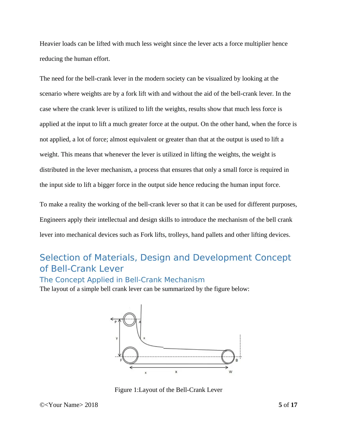
The layout of a simple bell crank lever can be summarized by the figure below:
Figure 1:Layout of the Bell-Crank Lever
©<Your Name> 2018 5 of 17
reducing the human effort.
The need for the bell-crank lever in the modern society can be visualized by looking at the
scenario where weights are by a fork lift with and without the aid of the bell-crank lever. In the
case where the crank lever is utilized to lift the weights, results show that much less force is
applied at the input to lift a much greater force at the output. On the other hand, when the force is
not applied, a lot of force; almost equivalent or greater than that at the output is used to lift a
weight. This means that whenever the lever is utilized in lifting the weights, the weight is
distributed in the lever mechanism, a process that ensures that only a small force is required in
the input side to lift a bigger force in the output side hence reducing the human input force.
To make a reality the working of the bell-crank lever so that it can be used for different purposes,
Engineers apply their intellectual and design skills to introduce the mechanism of the bell crank
lever into mechanical devices such as Fork lifts, trolleys, hand pallets and other lifting devices.
Selection of Materials, Design and Development Concept
of Bell-Crank Lever
The Concept Applied in Bell-Crank Mechanism
The layout of a simple bell crank lever can be summarized by the figure below:
Figure 1:Layout of the Bell-Crank Lever
©<Your Name> 2018 5 of 17
In the layout of the Bell-Crank lever shown above, the effort applied at point P is used to counter
the weight of the load W. A represents the entry point of vertical end pin, while point B indicates
the point of the pin that joins the lever extending up to the middle of the fulcrum. The fulcrum is
the point denoted by F. To come up with the mathematical representation of the of the bell-crank
lever, we let X be the distance separating the fulcrum and the point of the pin that joins the lever
and Y be the length separating the fulcrum and the entry point of the vertical pin A. Furthermore
the following constants are declared σ is used to represent the most appropriate bending stress
while the lever is in tension. Moreover, τ is used to indicate the most appropriate stress while the
lever is in shear and P the bearing pressure of the pin.
If the moments about the point F are to be considered, we come up with the following
mathematical computation
Wx=Py
Hence when we equate for P, we get the following expression
P= Wx
y N
With the above two equations, the reaction on the fulcrum pin can be obtained with the below
expression.
R= √ ( P2+W 2 ) N
The Fulcrum Point Design
The next step in the design of the lever involves the design of the fulcrum point. The design of
this point ensures proper functioning of the lever by ensuring that the weight from the input side
is properly distributed to facilitate the heavier weight on the output side. In this design, we let L
©<Your Name> 2018 6 of 17
⊘ This is a preview!⊘
Do you want full access?
Subscribe today to unlock all pages.
Trusted by 1+ million students worldwide
be the thickness of the fulcrum pin and d be its diameter. If the fulcrum or the support is let to be
in the bearing, then the following expression is drawn.
R= ( DXLXP ) N
The above equation is factored to come up with the expression for the diameter of the fulcrum as
below
D= R
LPN
Once the value of the diameter of the thickness of the fulcrum is determined, the permissible
values for double shear stress that will be induced in the fulcrum pin is evaluated by the use of
the following equation:
τ calc= R
2 XπX d2
4
Once the fulcrum point is calculated and evaluated using the above set of equations, the points A
and B are determined and evaluated a s well.
Design for Point A
To determine this point, we first let the diameter of our pin A be d and L be the length of the
length or the thickness of the pin. If know pin A is let to be in the bearing, then P can v\be
determined using the following expression
P=DXLXP
Once the above equation is determined using the preset values the double shearing stress induced
at this point is again determined using the expression similar to the one obtained in the case of
the fulcrum design. If the determined and evaluated shear stress induced at this point is found to
©<Your Name> 2018 7 of 17
Paraphrase This Document
Need a fresh take? Get an instant paraphrase of this document with our AI Paraphraser
be within the permissible limits, then bending stress at this point is determined using the set of
formula’s below:
M=WFB
The sectional modulus of this point is determined using the following equation:
Z= 1
6 XlX d2
Know, with the above two sets of equations the bending stress is determined as follows:
σ = M
Z
In the design process, the above value should always be let to be within the permissible limit to
ensure safe, efficient and effect operation of the bell-crank lever.
Design of Point B
The design of this point is much similar to the design of point A, the only difference occurs when
we need to determine the bending stress induced at the point. Here, we apply the formula below:
M =WXFB−PXFA
All the other steps, resemble those of the design of point A. Again in the design of point B. It is
of great importance to ensure that the values of stress determined lie within the required safe
limits for sufficient operation.
Design of Lever
In the design of the lever, we choose a section on the x-x plane and assume that it is the weak
section at which there would occur a failure. The thickness and the width of the of the lever at
©<Your Name> 2018 8 of 17
the points x-x are assumed to be t and b. The maximum bending examined from the given
section x-x is thereby given using the following equation:
M =W (x−40)
The 40 is arrived at by assuming that the length of the given x-x examined form the middle point
of the fulcrum lies between thirty and fifty millimeters.
Z= 1
6 Xtx b2
And,
σ = M
Z
Again in this case, the calculated values should be within the permissible safe limits for efficient
operation and for ensuring the design objective is met perfectly.
Determination of Stress on the Effort Arm
In this case again, the thickness of the section x-x is assumed to be t while the thickness is
assumed to be b. The maximum bending moment and the section modulus in determined using
the criterion similar to the one above and values allowed to be with the permissible values.
The values of b and t and L for all the above designed components are determined from the
expression in each section and making special assumptions that would ensure that the final
product operates efficiently and effectively.
Selection of Material
The bell crank lever is applied in a wide range of field, some of which require the lifting of very
heavy materials. For this reason, the choice of the material to be used in its manufacture of great
©<Your Name> 2018 9 of 17
⊘ This is a preview!⊘
Do you want full access?
Subscribe today to unlock all pages.
Trusted by 1+ million students worldwide
significance. Majorly, the materials that are used in the design of the bell-crank lever are usually
metals. The metals selected should have a high value of stress and tension and shear. To ensure
that the above conditions are met, the design phase usually comprises the use of very heavy load
values to replicate practical loads. The commonly selected material for this purpose after design
and testing and to ensure that the resultant bell-crank lever is of high quality and can perform
well under any condition of load is usually any steel metal., the common one being the AISI
1045 Carbon steel (cold). The components in the steel used in the manufacture of the bell-crank
lever and their composition are as shown in the table below:
Iron 98.5-98.99%
Carbon 0.45%
Manganese 0.62%
Phosphorous 0.04%
Sulphur 0.05%
Table 1:Composition of Materials in steel
The steel used despite having the above composition of materials, should have the following
properties. Firstly, it should have an elongation of 12%, a Brinell hardness of 179, a shear
strength of 77Kpsi and a tensile strength of 92psi.
Manufacture of the Bell-Crank Lever
The manufacture of the lever begins by making the die of the shape of the lever that was
designed initially, after that, die casting is done to facilitate the process of bulk production. The
dyeing process requires the use of sand casting which ensures the replica of the lever is created
for die shape making. Once the above operation is complete, machining is done on the casting
produced during the latter process of die casting. Surface finish with the aid of sand papers and
©<Your Name> 2018 10 of 17
Paraphrase This Document
Need a fresh take? Get an instant paraphrase of this document with our AI Paraphraser
grinders follows to finish the manufacturing process. During this manufacturing process,
allowances are made to the calculated values so that the losses that occur as a result of shrinking,
surface treatment and machining are catered for in advance.
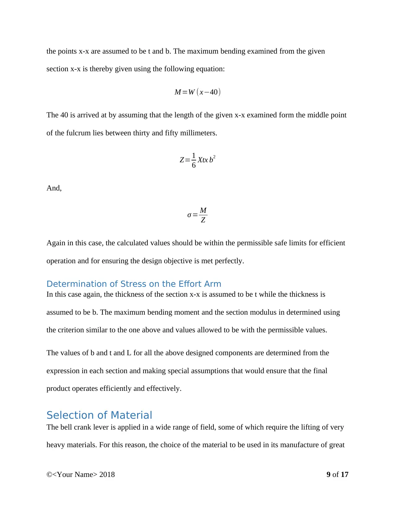
Schematic representations of the complete lever are as shown
Figure 2: Views of Crank lever
In the above to figures, the first one represents the side view of the solid form of the designed
bell-crank lever while the second represents the front view fo the designed bell crank lever.
Testing of the Bell-Crank Lever
Once the bell-crank lever has been designed and manufactured, the tseting face follows. The
testing of the lever requires the use of the Ansys software for analysis and the use of the FEM to
develop mesh of specified node tetrahedral solid element. Weight of specified amount is used to
determine if the design objectives are met. The figure below shows a sample image that is
developed during the testing phase.
©<Your Name> 2018 11 of 17
allowances are made to the calculated values so that the losses that occur as a result of shrinking,
surface treatment and machining are catered for in advance.
Schematic representations of the complete lever are as shown
Figure 2: Views of Crank lever
In the above to figures, the first one represents the side view of the solid form of the designed
bell-crank lever while the second represents the front view fo the designed bell crank lever.
Testing of the Bell-Crank Lever
Once the bell-crank lever has been designed and manufactured, the tseting face follows. The
testing of the lever requires the use of the Ansys software for analysis and the use of the FEM to
develop mesh of specified node tetrahedral solid element. Weight of specified amount is used to
determine if the design objectives are met. The figure below shows a sample image that is
developed during the testing phase.
©<Your Name> 2018 11 of 17
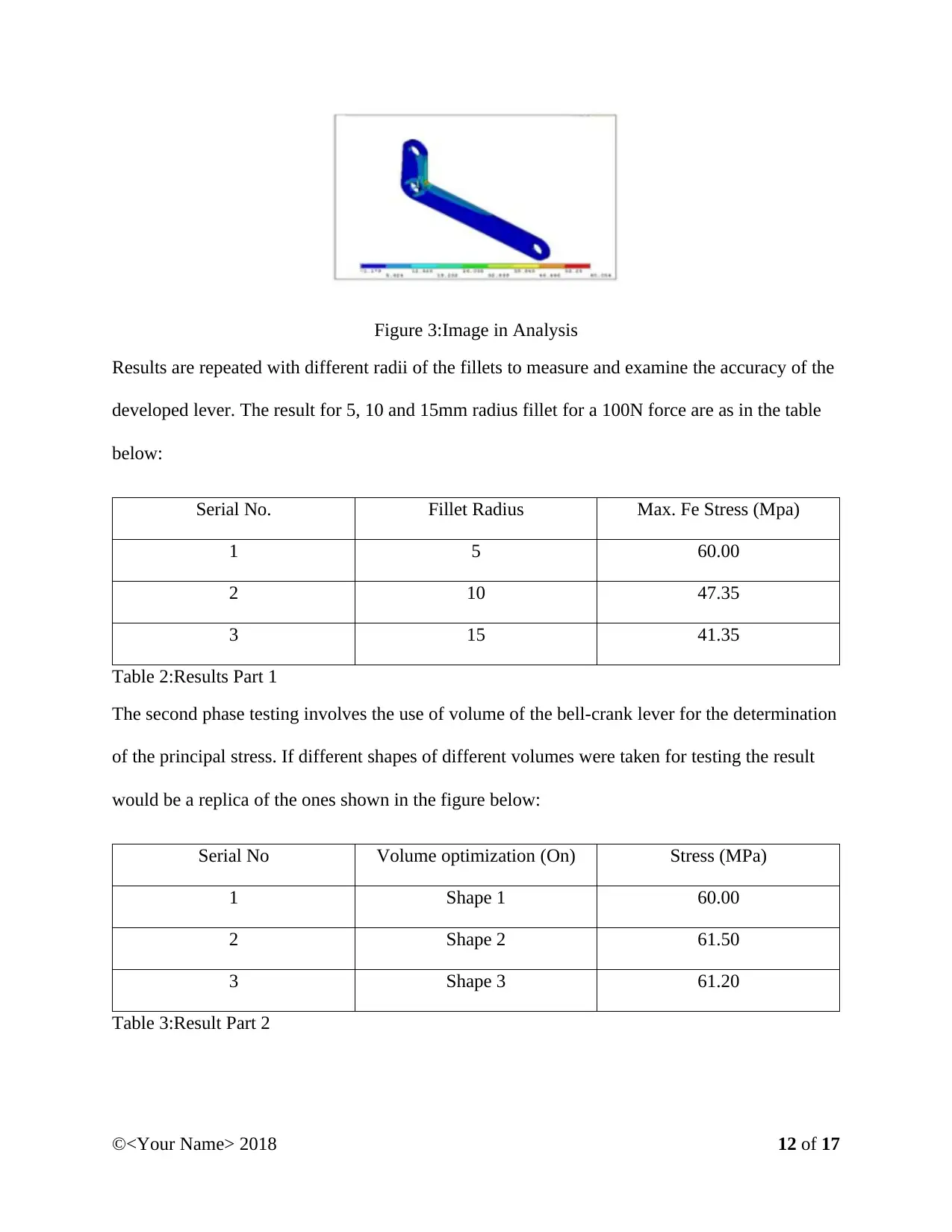
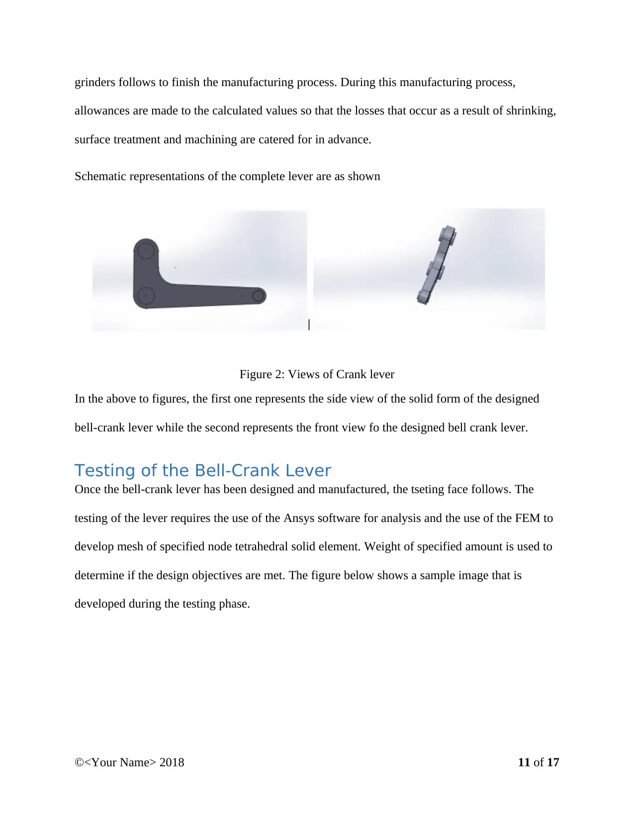
Figure 3:Image in Analysis
Results are repeated with different radii of the fillets to measure and examine the accuracy of the
developed lever. The result for 5, 10 and 15mm radius fillet for a 100N force are as in the table
below:
Serial No. Fillet Radius Max. Fe Stress (Mpa)
1 5 60.00
2 10 47.35
3 15 41.35
Table 2:Results Part 1
The second phase testing involves the use of volume of the bell-crank lever for the determination
of the principal stress. If different shapes of different volumes were taken for testing the result
would be a replica of the ones shown in the figure below:
Serial No Volume optimization (On) Stress (MPa)
1 Shape 1 60.00
2 Shape 2 61.50
3 Shape 3 61.20
Table 3:Result Part 2
©<Your Name> 2018 12 of 17
⊘ This is a preview!⊘
Do you want full access?
Subscribe today to unlock all pages.
Trusted by 1+ million students worldwide
1 out of 17
Related Documents


Your All-in-One AI-Powered Toolkit for Academic Success.
+13062052269
info@desklib.com
Available 24*7 on WhatsApp / Email
![[object Object]](/_next/static/media/star-bottom.7253800d.svg)
Unlock your academic potential
Copyright © 2020–2026 A2Z Services. All Rights Reserved. Developed and managed by ZUCOL.