Design and Analysis of a Three-System Bicycle Balancing Control
VerifiedAdded on 2020/03/23
|14
|3190
|37
Project
AI Summary
This project delves into the design and analysis of bicycle balancing control systems, drawing inspiration from Gyrowheel, training wheels, Gyrover, and Ghostrider. The project begins with an introduction to the 'inverted pendulum' problem, which serves as an analogy for bicycle balancing, and then explores data collection and analysis from passive systems like Gyrowheel and training wheels, and active systems like Gyrover and Ghostrider. The core of the project involves the development of a gyroscopic balance system using a flywheel and an arm support system, including detailed mathematical analyses of gyroscopic torque and the equations governing the arm support system's operation. The project also addresses balance strategies, including ground contact, tilt angle correction, and tilt dampening, along with the design of the chassis, actuation subsystems, computation systems, and sensing systems. The electrical integration of these components, including power and signal integration, is also detailed. Finally, the project presents results and data analysis, including the prototype and its components, such as the motor mounting plate, providing a comprehensive overview of the design and implementation of a bicycle balancing system.

BICYCLE BALANCING CONTROL
Student’s Name
Class
Tutor’s Name
Institution’s Name
City
Date
Student’s Name
Class
Tutor’s Name
Institution’s Name
City
Date
Paraphrase This Document
Need a fresh take? Get an instant paraphrase of this document with our AI Paraphraser
Balancing 2
Contents
Executive summary.....................................................................................................................................3
Introduction.................................................................................................................................................3
Data collection.............................................................................................................................................3
Project Database.........................................................................................................................................6
Results and data analysis...........................................................................................................................11
4.1 Data analysis........................................................................................................................................12
Conclusion.................................................................................................................................................13
Bibliography...............................................................................................................................................14
Balancing 3
Executive summary
The project takes into account the features present in Gyrowheel, training wheels, Gyrover and ghost
rider balancing system. The balancing obtained in these designs are produced from equations that are to
be discussed and applied in the resulting bicycle balancing system that will be developed [1]. Additional
features are also included to make the bicycle affordable and make it not influence the experience in
riding the bicycle. This developed bicycle balancing system can be applied in therapeutic studies, by
children who intend to learn riding and injured adults [2].
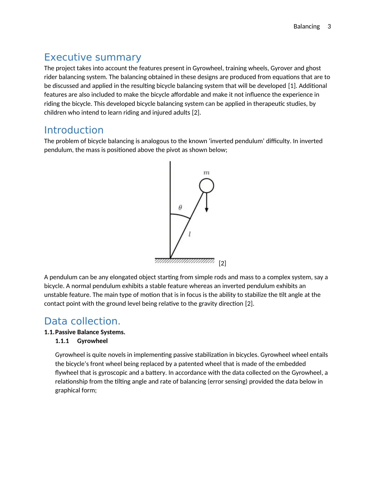
Introduction
The problem of bicycle balancing is analogous to the known ‘inverted pendulum’ difficulty. In inverted
pendulum, the mass is positioned above the pivot as shown below;
[2]
A pendulum can be any elongated object starting from simple rods and mass to a complex system, say a
bicycle. A normal pendulum exhibits a stable feature whereas an inverted pendulum exhibits an
unstable feature. The main type of motion that is in focus is the ability to stabilize the tilt angle at the
contact point with the ground level being relative to the gravity direction [2].
Data collection.
1.1.Passive Balance Systems.
1.1.1 Gyrowheel
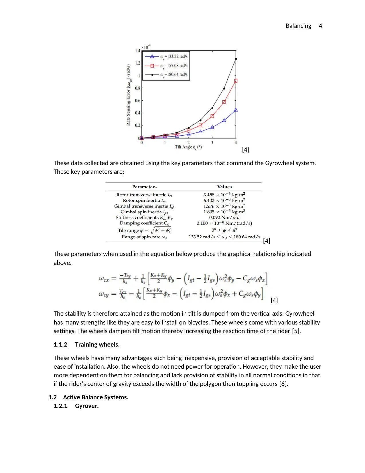
Gyrowheel is quite novels in implementing passive stabilization in bicycles. Gyrowheel wheel entails
the bicycle’s front wheel being replaced by a patented wheel that is made of the embedded
flywheel that is gyroscopic and a battery. In accordance with the data collected on the Gyrowheel, a
relationship from the tilting angle and rate of balancing (error sensing) provided the data below in
graphical form;
Executive summary
The project takes into account the features present in Gyrowheel, training wheels, Gyrover and ghost
rider balancing system. The balancing obtained in these designs are produced from equations that are to
be discussed and applied in the resulting bicycle balancing system that will be developed [1]. Additional
features are also included to make the bicycle affordable and make it not influence the experience in
riding the bicycle. This developed bicycle balancing system can be applied in therapeutic studies, by
children who intend to learn riding and injured adults [2].
Introduction
The problem of bicycle balancing is analogous to the known ‘inverted pendulum’ difficulty. In inverted
pendulum, the mass is positioned above the pivot as shown below;
[2]
A pendulum can be any elongated object starting from simple rods and mass to a complex system, say a
bicycle. A normal pendulum exhibits a stable feature whereas an inverted pendulum exhibits an
unstable feature. The main type of motion that is in focus is the ability to stabilize the tilt angle at the
contact point with the ground level being relative to the gravity direction [2].
Data collection.
1.1.Passive Balance Systems.
1.1.1 Gyrowheel
Gyrowheel is quite novels in implementing passive stabilization in bicycles. Gyrowheel wheel entails
the bicycle’s front wheel being replaced by a patented wheel that is made of the embedded
flywheel that is gyroscopic and a battery. In accordance with the data collected on the Gyrowheel, a
relationship from the tilting angle and rate of balancing (error sensing) provided the data below in
graphical form;
⊘ This is a preview!⊘
Do you want full access?
Subscribe today to unlock all pages.
Trusted by 1+ million students worldwide
Balancing 4
[4]
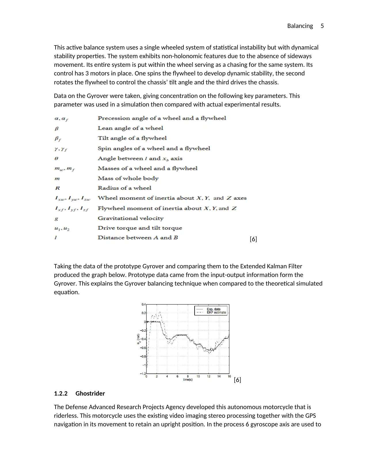
These data collected are obtained using the key parameters that command the Gyrowheel system.
These key parameters are;
[4]
These parameters when used in the equation below produce the graphical relationship indicated
above.
[4]
The stability is therefore attained as the motion in tilt is dumped from the vertical axis. Gyrowheel
has many strengths like they are easy to install on bicycles. These wheels come with various stability
settings. The wheels dampen tilt motion thereby increasing the reaction time of the rider [5].
1.1.2 Training wheels.
These wheels have many advantages such being inexpensive, provision of acceptable stability and
ease of installation. Also, the wheels do not need power for operation. However, they make the user
more dependent on them for balancing and lack provision of stability in all normal conditions in that
if the rider’s center of gravity exceeds the width of the polygon then toppling occurs [6].
1.2 Active Balance Systems.
1.2.1 Gyrover.
[4]
These data collected are obtained using the key parameters that command the Gyrowheel system.
These key parameters are;
[4]
These parameters when used in the equation below produce the graphical relationship indicated
above.
[4]
The stability is therefore attained as the motion in tilt is dumped from the vertical axis. Gyrowheel
has many strengths like they are easy to install on bicycles. These wheels come with various stability
settings. The wheels dampen tilt motion thereby increasing the reaction time of the rider [5].
1.1.2 Training wheels.
These wheels have many advantages such being inexpensive, provision of acceptable stability and
ease of installation. Also, the wheels do not need power for operation. However, they make the user
more dependent on them for balancing and lack provision of stability in all normal conditions in that
if the rider’s center of gravity exceeds the width of the polygon then toppling occurs [6].
1.2 Active Balance Systems.
1.2.1 Gyrover.
Paraphrase This Document
Need a fresh take? Get an instant paraphrase of this document with our AI Paraphraser
Balancing 5
This active balance system uses a single wheeled system of statistical instability but with dynamical
stability properties. The system exhibits non-holonomic features due to the absence of sideways
movement. Its entire system is put within the wheel serving as a chasing for the same system. Its
control has 3 motors in place. One spins the flywheel to develop dynamic stability, the second
rotates the flywheel to control the chassis’ tilt angle and the third drives the chassis.
Data on the Gyrover were taken, giving concentration on the following key parameters. This
parameter was used in a simulation then compared with actual experimental results.
[6]
Taking the data of the prototype Gyrover and comparing them to the Extended Kalman Filter
produced the graph below. Prototype data came from the input-output information form the
Gyrover. This explains the Gyrover balancing technique when compared to the theoretical simulated
equation.
[6]
1.2.2 Ghostrider
The Defense Advanced Research Projects Agency developed this autonomous motorcycle that is
riderless. This motorcycle uses the existing video imaging stereo processing together with the GPS
navigation in its movement to retain an upright position. In the process 6 gyroscope axis are used to
Balancing 6
provide its orientation and calculate the angular velocity. Its degree of turning is very small that it
does not inhibit the motorcycles ability to successfully navigate. However, the motorcycle weaves as
it moves forward due to the stabilizing nature in a radius of turns that balance its movement [8]
Project Database
The section at hand takes one through the developmental progression of the major designs in this
projected system together with the methodology used in implementing an actuated system arm
support. There is a detailed information the different subsystems and the integration in the completion
of the mentioned design [10].
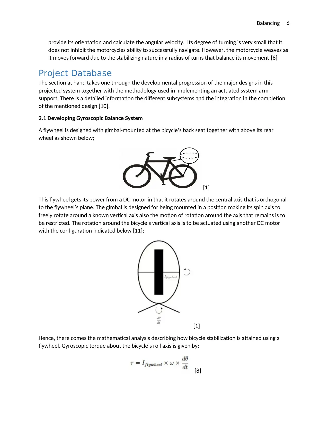
2.1 Developing Gyroscopic Balance System
A flywheel is designed with gimbal-mounted at the bicycle’s back seat together with above its rear
wheel as shown below;
[1]
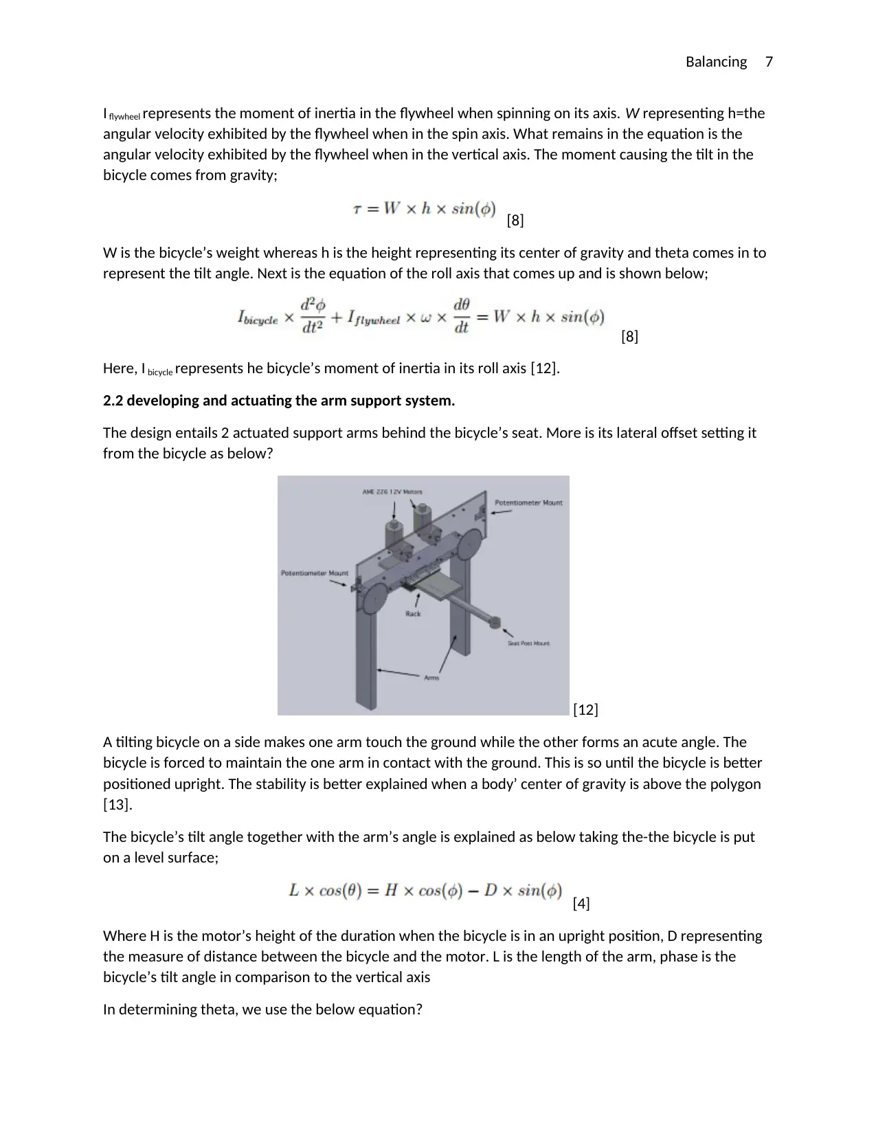
This flywheel gets its power from a DC motor in that it rotates around the central axis that is orthogonal
to the flywheel’s plane. The gimbal is designed for being mounted in a position making its spin axis to
freely rotate around a known vertical axis also the motion of rotation around the axis that remains is to
be restricted. The rotation around the bicycle’s vertical axis is to be actuated using another DC motor
with the configuration indicated below [11];
[1]
Hence, there comes the mathematical analysis describing how bicycle stabilization is attained using a
flywheel. Gyroscopic torque about the bicycle’s roll axis is given by;
[8]
provide its orientation and calculate the angular velocity. Its degree of turning is very small that it
does not inhibit the motorcycles ability to successfully navigate. However, the motorcycle weaves as
it moves forward due to the stabilizing nature in a radius of turns that balance its movement [8]
Project Database
The section at hand takes one through the developmental progression of the major designs in this
projected system together with the methodology used in implementing an actuated system arm
support. There is a detailed information the different subsystems and the integration in the completion
of the mentioned design [10].
2.1 Developing Gyroscopic Balance System
A flywheel is designed with gimbal-mounted at the bicycle’s back seat together with above its rear
wheel as shown below;
[1]
This flywheel gets its power from a DC motor in that it rotates around the central axis that is orthogonal
to the flywheel’s plane. The gimbal is designed for being mounted in a position making its spin axis to
freely rotate around a known vertical axis also the motion of rotation around the axis that remains is to
be restricted. The rotation around the bicycle’s vertical axis is to be actuated using another DC motor
with the configuration indicated below [11];
[1]
Hence, there comes the mathematical analysis describing how bicycle stabilization is attained using a
flywheel. Gyroscopic torque about the bicycle’s roll axis is given by;
[8]
⊘ This is a preview!⊘
Do you want full access?
Subscribe today to unlock all pages.
Trusted by 1+ million students worldwide
Balancing 7
I flywheel represents the moment of inertia in the flywheel when spinning on its axis. W representing h=the
angular velocity exhibited by the flywheel when in the spin axis. What remains in the equation is the
angular velocity exhibited by the flywheel when in the vertical axis. The moment causing the tilt in the
bicycle comes from gravity;
[8]
W is the bicycle’s weight whereas h is the height representing its center of gravity and theta comes in to
represent the tilt angle. Next is the equation of the roll axis that comes up and is shown below;
[8]
Here, I bicycle represents he bicycle’s moment of inertia in its roll axis [12].
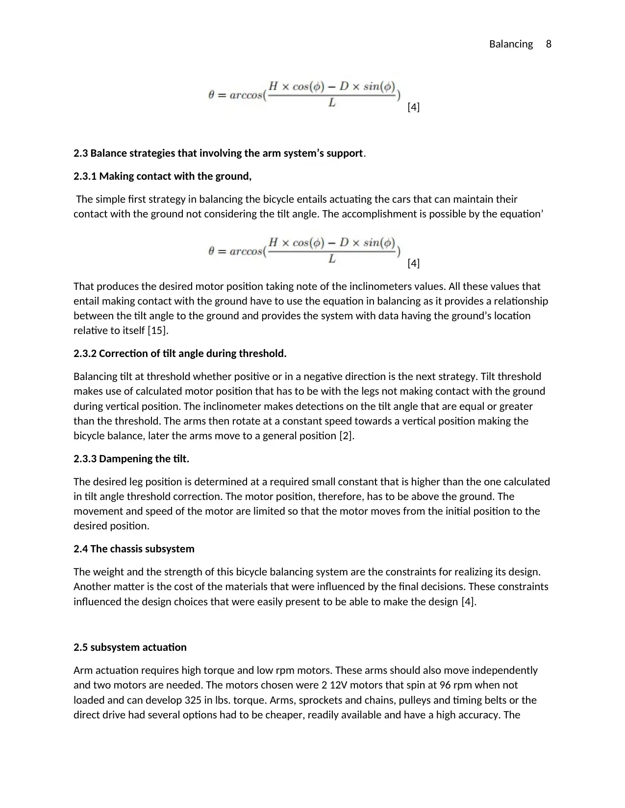
2.2 developing and actuating the arm support system.
The design entails 2 actuated support arms behind the bicycle’s seat. More is its lateral offset setting it
from the bicycle as below?
[12]
A tilting bicycle on a side makes one arm touch the ground while the other forms an acute angle. The
bicycle is forced to maintain the one arm in contact with the ground. This is so until the bicycle is better
positioned upright. The stability is better explained when a body’ center of gravity is above the polygon
[13].
The bicycle’s tilt angle together with the arm’s angle is explained as below taking the-the bicycle is put
on a level surface;
[4]
Where H is the motor’s height of the duration when the bicycle is in an upright position, D representing
the measure of distance between the bicycle and the motor. L is the length of the arm, phase is the
bicycle’s tilt angle in comparison to the vertical axis
In determining theta, we use the below equation?
I flywheel represents the moment of inertia in the flywheel when spinning on its axis. W representing h=the
angular velocity exhibited by the flywheel when in the spin axis. What remains in the equation is the
angular velocity exhibited by the flywheel when in the vertical axis. The moment causing the tilt in the
bicycle comes from gravity;
[8]
W is the bicycle’s weight whereas h is the height representing its center of gravity and theta comes in to
represent the tilt angle. Next is the equation of the roll axis that comes up and is shown below;
[8]
Here, I bicycle represents he bicycle’s moment of inertia in its roll axis [12].
2.2 developing and actuating the arm support system.
The design entails 2 actuated support arms behind the bicycle’s seat. More is its lateral offset setting it
from the bicycle as below?
[12]
A tilting bicycle on a side makes one arm touch the ground while the other forms an acute angle. The
bicycle is forced to maintain the one arm in contact with the ground. This is so until the bicycle is better
positioned upright. The stability is better explained when a body’ center of gravity is above the polygon
[13].
The bicycle’s tilt angle together with the arm’s angle is explained as below taking the-the bicycle is put
on a level surface;
[4]
Where H is the motor’s height of the duration when the bicycle is in an upright position, D representing
the measure of distance between the bicycle and the motor. L is the length of the arm, phase is the
bicycle’s tilt angle in comparison to the vertical axis
In determining theta, we use the below equation?
Paraphrase This Document
Need a fresh take? Get an instant paraphrase of this document with our AI Paraphraser
Balancing 8
[4]
2.3 Balance strategies that involving the arm system’s support.
2.3.1 Making contact with the ground,
The simple first strategy in balancing the bicycle entails actuating the cars that can maintain their
contact with the ground not considering the tilt angle. The accomplishment is possible by the equation’
[4]
That produces the desired motor position taking note of the inclinometers values. All these values that
entail making contact with the ground have to use the equation in balancing as it provides a relationship
between the tilt angle to the ground and provides the system with data having the ground’s location
relative to itself [15].
2.3.2 Correction of tilt angle during threshold.
Balancing tilt at threshold whether positive or in a negative direction is the next strategy. Tilt threshold
makes use of calculated motor position that has to be with the legs not making contact with the ground
during vertical position. The inclinometer makes detections on the tilt angle that are equal or greater
than the threshold. The arms then rotate at a constant speed towards a vertical position making the
bicycle balance, later the arms move to a general position [2].
2.3.3 Dampening the tilt.
The desired leg position is determined at a required small constant that is higher than the one calculated
in tilt angle threshold correction. The motor position, therefore, has to be above the ground. The
movement and speed of the motor are limited so that the motor moves from the initial position to the
desired position.
2.4 The chassis subsystem
The weight and the strength of this bicycle balancing system are the constraints for realizing its design.
Another matter is the cost of the materials that were influenced by the final decisions. These constraints
influenced the design choices that were easily present to be able to make the design [4].
2.5 subsystem actuation
Arm actuation requires high torque and low rpm motors. These arms should also move independently
and two motors are needed. The motors chosen were 2 12V motors that spin at 96 rpm when not
loaded and can develop 325 in lbs. torque. Arms, sprockets and chains, pulleys and timing belts or the
direct drive had several options had to be cheaper, readily available and have a high accuracy. The
[4]
2.3 Balance strategies that involving the arm system’s support.
2.3.1 Making contact with the ground,
The simple first strategy in balancing the bicycle entails actuating the cars that can maintain their
contact with the ground not considering the tilt angle. The accomplishment is possible by the equation’
[4]
That produces the desired motor position taking note of the inclinometers values. All these values that
entail making contact with the ground have to use the equation in balancing as it provides a relationship
between the tilt angle to the ground and provides the system with data having the ground’s location
relative to itself [15].
2.3.2 Correction of tilt angle during threshold.
Balancing tilt at threshold whether positive or in a negative direction is the next strategy. Tilt threshold
makes use of calculated motor position that has to be with the legs not making contact with the ground
during vertical position. The inclinometer makes detections on the tilt angle that are equal or greater
than the threshold. The arms then rotate at a constant speed towards a vertical position making the
bicycle balance, later the arms move to a general position [2].
2.3.3 Dampening the tilt.
The desired leg position is determined at a required small constant that is higher than the one calculated
in tilt angle threshold correction. The motor position, therefore, has to be above the ground. The
movement and speed of the motor are limited so that the motor moves from the initial position to the
desired position.
2.4 The chassis subsystem
The weight and the strength of this bicycle balancing system are the constraints for realizing its design.
Another matter is the cost of the materials that were influenced by the final decisions. These constraints
influenced the design choices that were easily present to be able to make the design [4].
2.5 subsystem actuation
Arm actuation requires high torque and low rpm motors. These arms should also move independently
and two motors are needed. The motors chosen were 2 12V motors that spin at 96 rpm when not
loaded and can develop 325 in lbs. torque. Arms, sprockets and chains, pulleys and timing belts or the
direct drive had several options had to be cheaper, readily available and have a high accuracy. The
Balancing 9
compensation the lack of accuracy there was a PID loop in control that determined the actual arm
position [5].
2.6 subsystem computation.
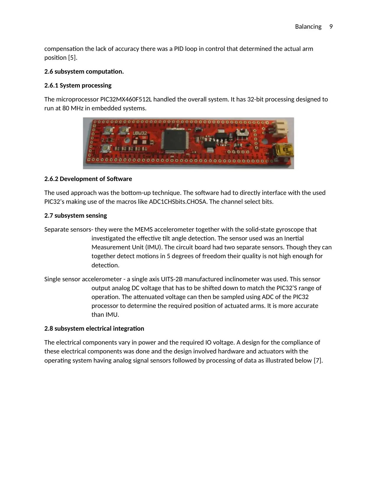
2.6.1 System processing
The microprocessor PIC32MX460F512L handled the overall system. It has 32-bit processing designed to
run at 80 MHz in embedded systems.
2.6.2 Development of Software
The used approach was the bottom-up technique. The software had to directly interface with the used
PIC32’s making use of the macros like ADC1CHSbits.CHOSA. The channel select bits.
2.7 subsystem sensing
Separate sensors- they were the MEMS accelerometer together with the solid-state gyroscope that
investigated the effective tilt angle detection. The sensor used was an Inertial
Measurement Unit (IMU). The circuit board had two separate sensors. Though they can
together detect motions in 5 degrees of freedom their quality is not high enough for
detection.
Single sensor accelerometer - a single axis UITS-2B manufactured inclinometer was used. This sensor
output analog DC voltage that has to be shifted down to match the PIC32’S range of
operation. The attenuated voltage can then be sampled using ADC of the PIC32
processor to determine the required position of actuated arms. It is more accurate
than IMU.
2.8 subsystem electrical integration
The electrical components vary in power and the required IO voltage. A design for the compliance of
these electrical components was done and the design involved hardware and actuators with the
operating system having analog signal sensors followed by processing of data as illustrated below [7].
compensation the lack of accuracy there was a PID loop in control that determined the actual arm
position [5].
2.6 subsystem computation.
2.6.1 System processing
The microprocessor PIC32MX460F512L handled the overall system. It has 32-bit processing designed to
run at 80 MHz in embedded systems.
2.6.2 Development of Software
The used approach was the bottom-up technique. The software had to directly interface with the used
PIC32’s making use of the macros like ADC1CHSbits.CHOSA. The channel select bits.
2.7 subsystem sensing
Separate sensors- they were the MEMS accelerometer together with the solid-state gyroscope that
investigated the effective tilt angle detection. The sensor used was an Inertial
Measurement Unit (IMU). The circuit board had two separate sensors. Though they can
together detect motions in 5 degrees of freedom their quality is not high enough for
detection.
Single sensor accelerometer - a single axis UITS-2B manufactured inclinometer was used. This sensor
output analog DC voltage that has to be shifted down to match the PIC32’S range of
operation. The attenuated voltage can then be sampled using ADC of the PIC32
processor to determine the required position of actuated arms. It is more accurate
than IMU.
2.8 subsystem electrical integration
The electrical components vary in power and the required IO voltage. A design for the compliance of
these electrical components was done and the design involved hardware and actuators with the
operating system having analog signal sensors followed by processing of data as illustrated below [7].
⊘ This is a preview!⊘
Do you want full access?
Subscribe today to unlock all pages.
Trusted by 1+ million students worldwide
Balancing 10
[4]
2.8.1 Power integration System
The power requirements are overall as below;
[10]
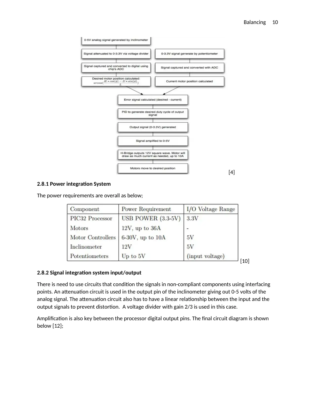
2.8.2 Signal integration system input/output
There is need to use circuits that condition the signals in non-compliant components using interfacing
points. An attenuation circuit is used in the output pin of the inclinometer giving out 0-5 volts of the
analog signal. The attenuation circuit also has to have a linear relationship between the input and the
output signals to prevent distortion. A voltage divider with gain 2/3 is used in this case.
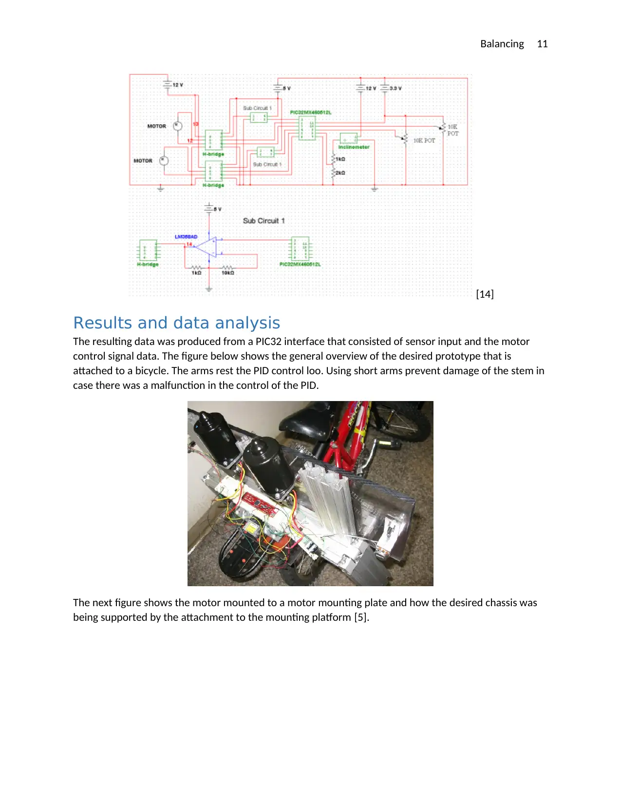
Amplification is also key between the processor digital output pins. The final circuit diagram is shown
below [12];
[4]
2.8.1 Power integration System
The power requirements are overall as below;
[10]
2.8.2 Signal integration system input/output
There is need to use circuits that condition the signals in non-compliant components using interfacing
points. An attenuation circuit is used in the output pin of the inclinometer giving out 0-5 volts of the
analog signal. The attenuation circuit also has to have a linear relationship between the input and the
output signals to prevent distortion. A voltage divider with gain 2/3 is used in this case.
Amplification is also key between the processor digital output pins. The final circuit diagram is shown
below [12];
Paraphrase This Document
Need a fresh take? Get an instant paraphrase of this document with our AI Paraphraser
Balancing 11
[14]
Results and data analysis
The resulting data was produced from a PIC32 interface that consisted of sensor input and the motor
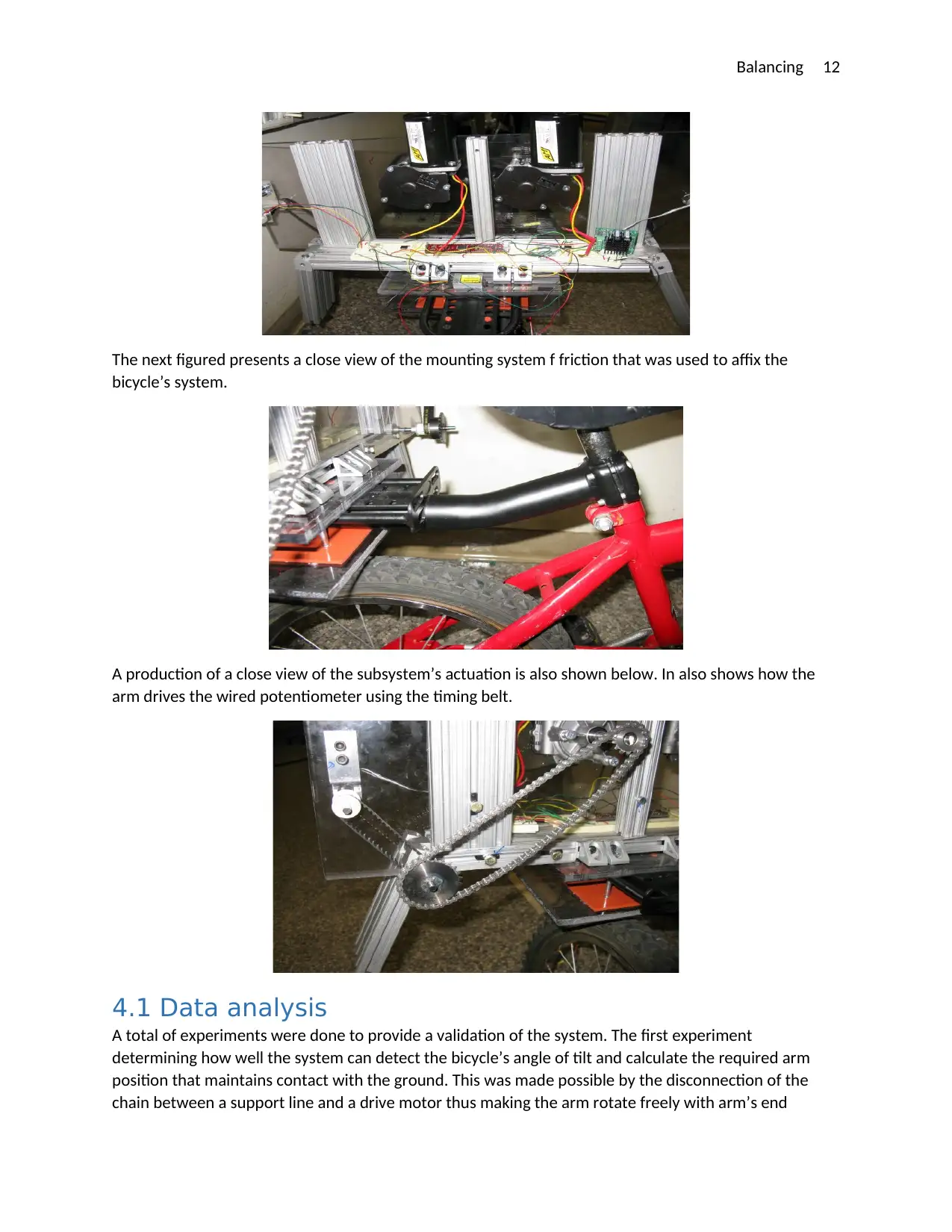
control signal data. The figure below shows the general overview of the desired prototype that is
attached to a bicycle. The arms rest the PID control loo. Using short arms prevent damage of the stem in
case there was a malfunction in the control of the PID.
The next figure shows the motor mounted to a motor mounting plate and how the desired chassis was
being supported by the attachment to the mounting platform [5].
[14]
Results and data analysis
The resulting data was produced from a PIC32 interface that consisted of sensor input and the motor
control signal data. The figure below shows the general overview of the desired prototype that is
attached to a bicycle. The arms rest the PID control loo. Using short arms prevent damage of the stem in
case there was a malfunction in the control of the PID.
The next figure shows the motor mounted to a motor mounting plate and how the desired chassis was
being supported by the attachment to the mounting platform [5].
Balancing 12
The next figured presents a close view of the mounting system f friction that was used to affix the
bicycle’s system.
A production of a close view of the subsystem’s actuation is also shown below. In also shows how the
arm drives the wired potentiometer using the timing belt.
4.1 Data analysis
A total of experiments were done to provide a validation of the system. The first experiment
determining how well the system can detect the bicycle’s angle of tilt and calculate the required arm
position that maintains contact with the ground. This was made possible by the disconnection of the
chain between a support line and a drive motor thus making the arm rotate freely with arm’s end
⊘ This is a preview!⊘
Do you want full access?
Subscribe today to unlock all pages.
Trusted by 1+ million students worldwide
1 out of 14

Your All-in-One AI-Powered Toolkit for Academic Success.
+13062052269
info@desklib.com
Available 24*7 on WhatsApp / Email
![[object Object]](/_next/static/media/star-bottom.7253800d.svg)
Unlock your academic potential
Copyright © 2020–2026 A2Z Services. All Rights Reserved. Developed and managed by ZUCOL.