IFSM Billing System Project: Functional and Technical Aspects
VerifiedAdded on 2019/10/18
|9
|1695
|157
Project
AI Summary
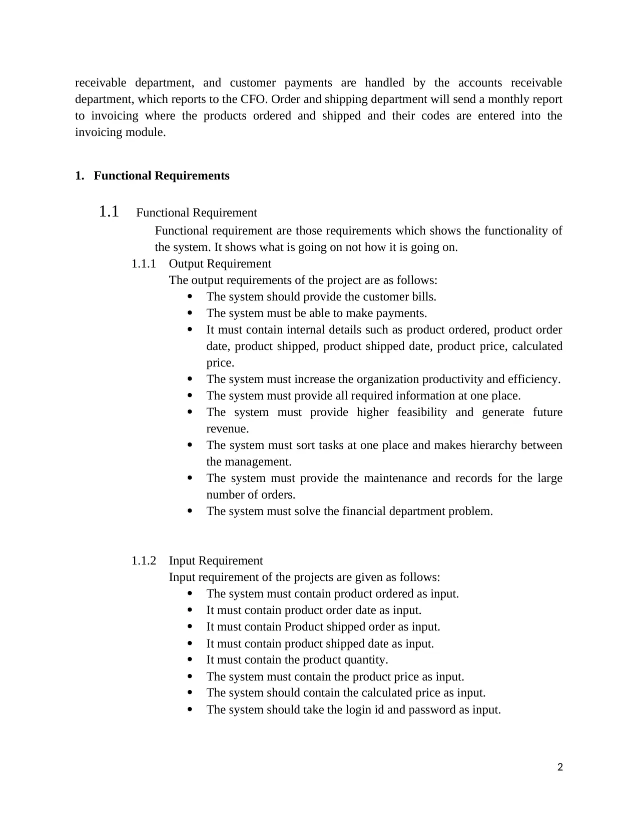
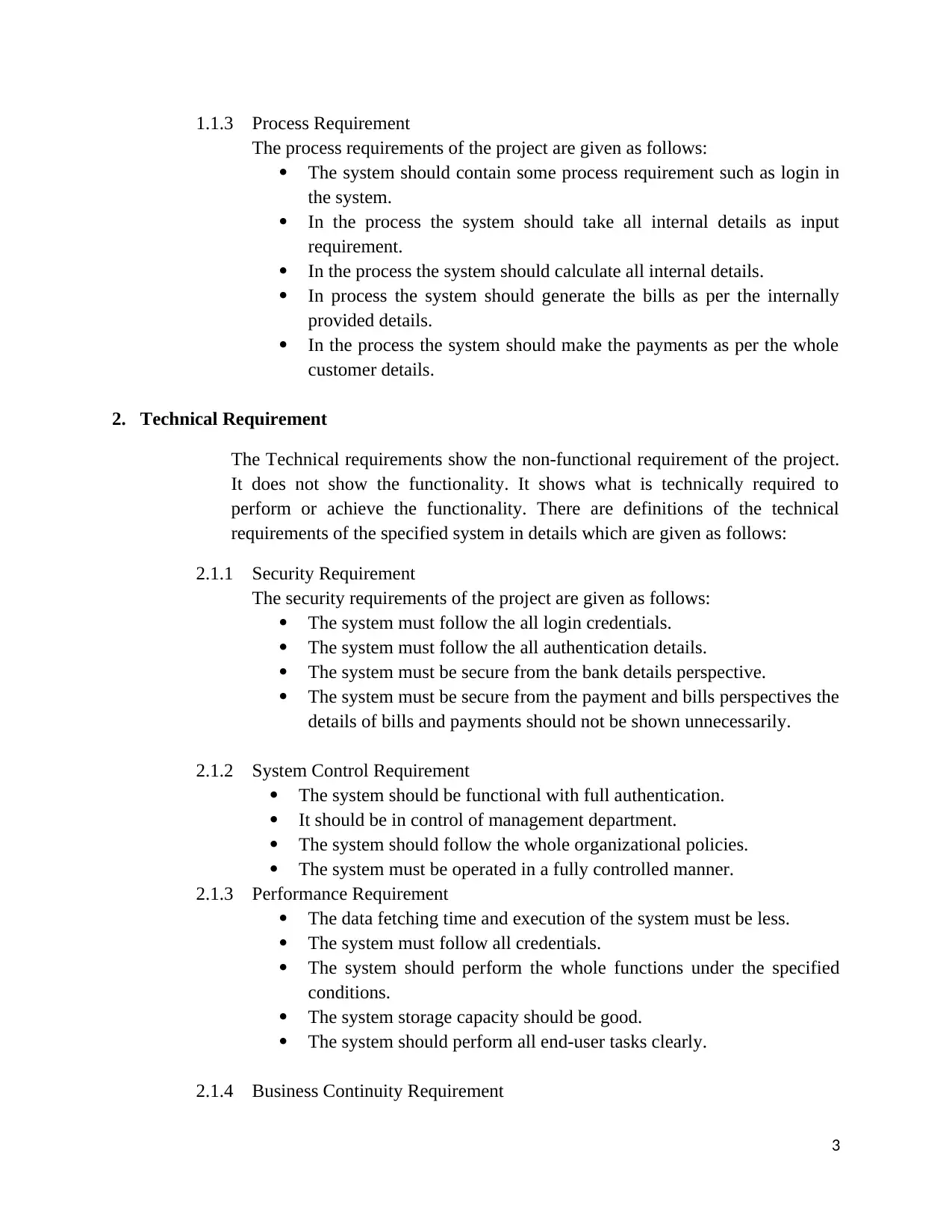
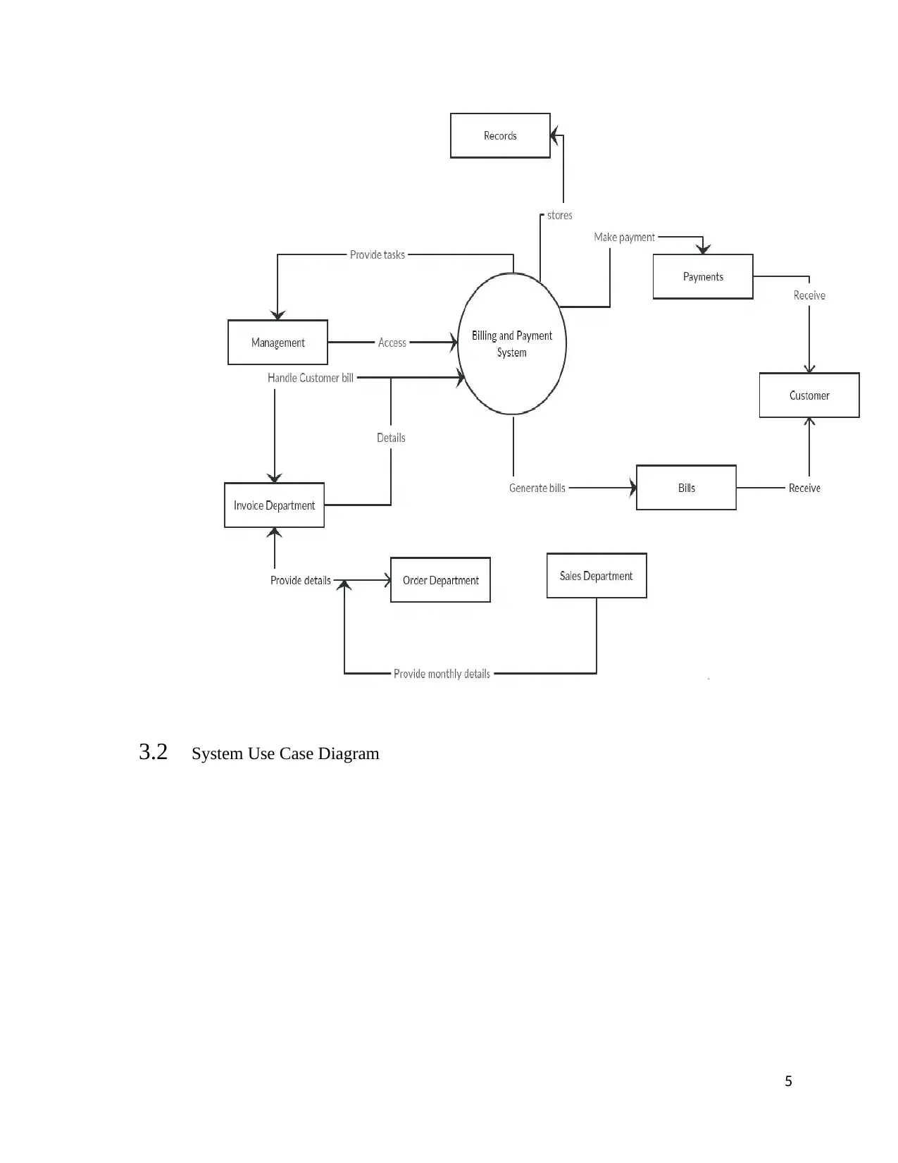
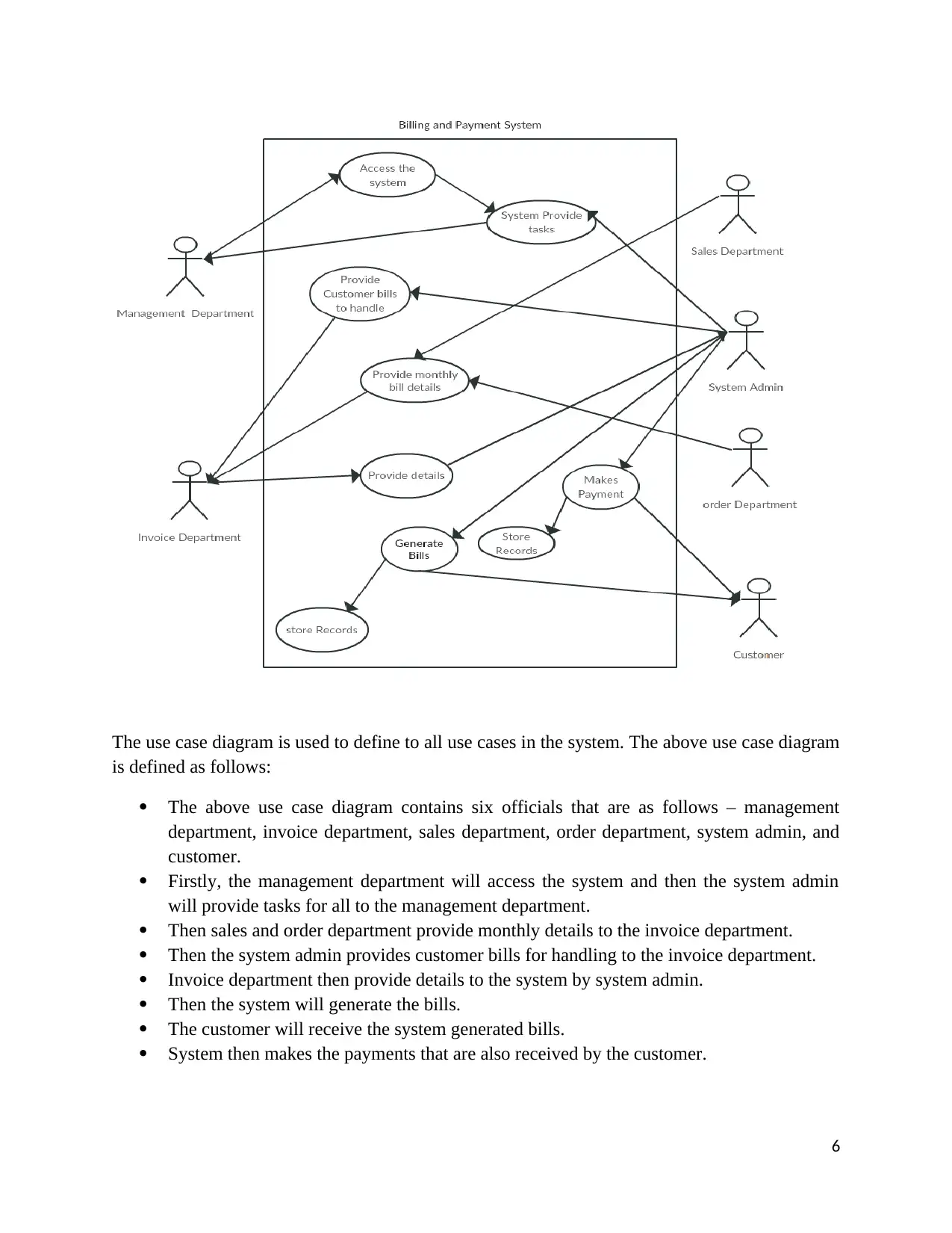
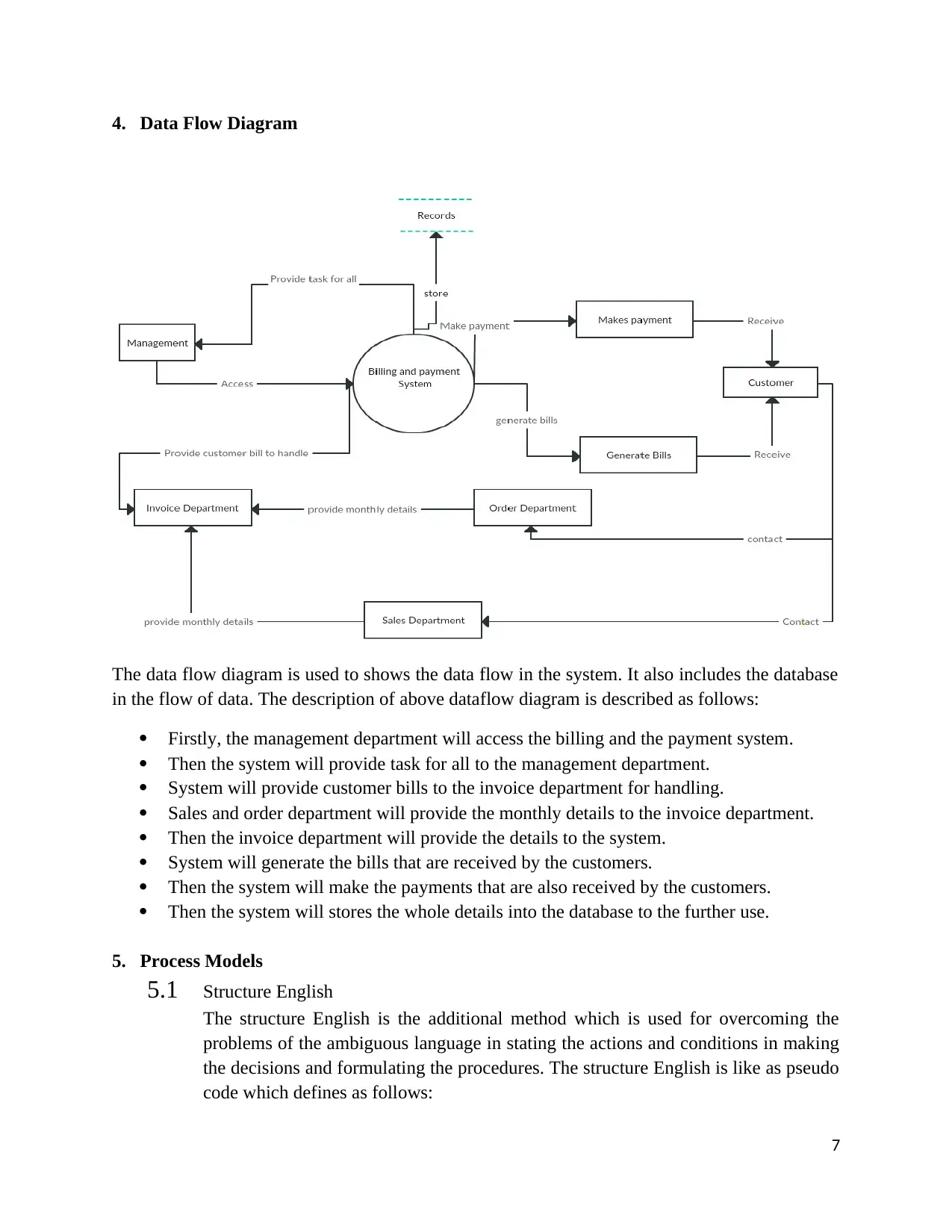
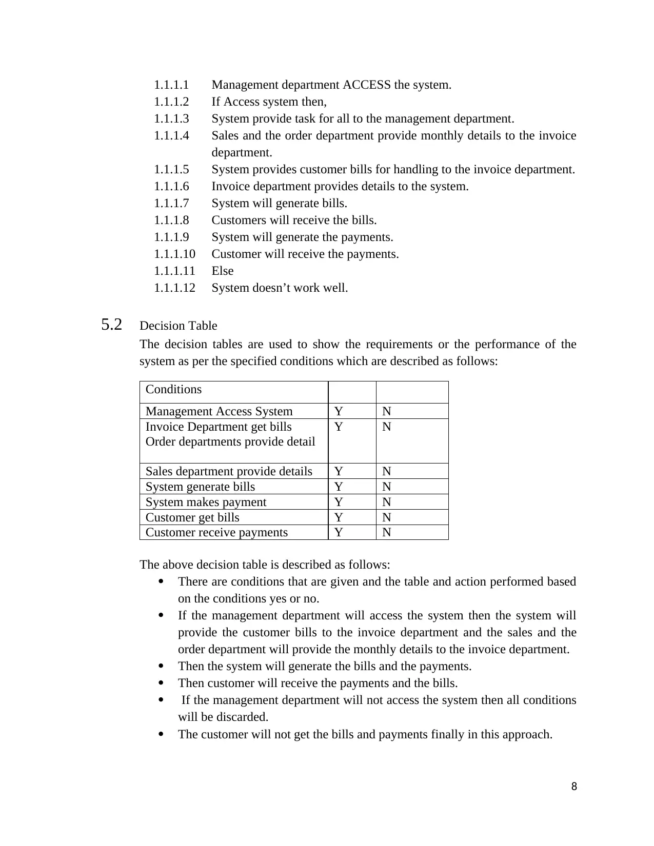
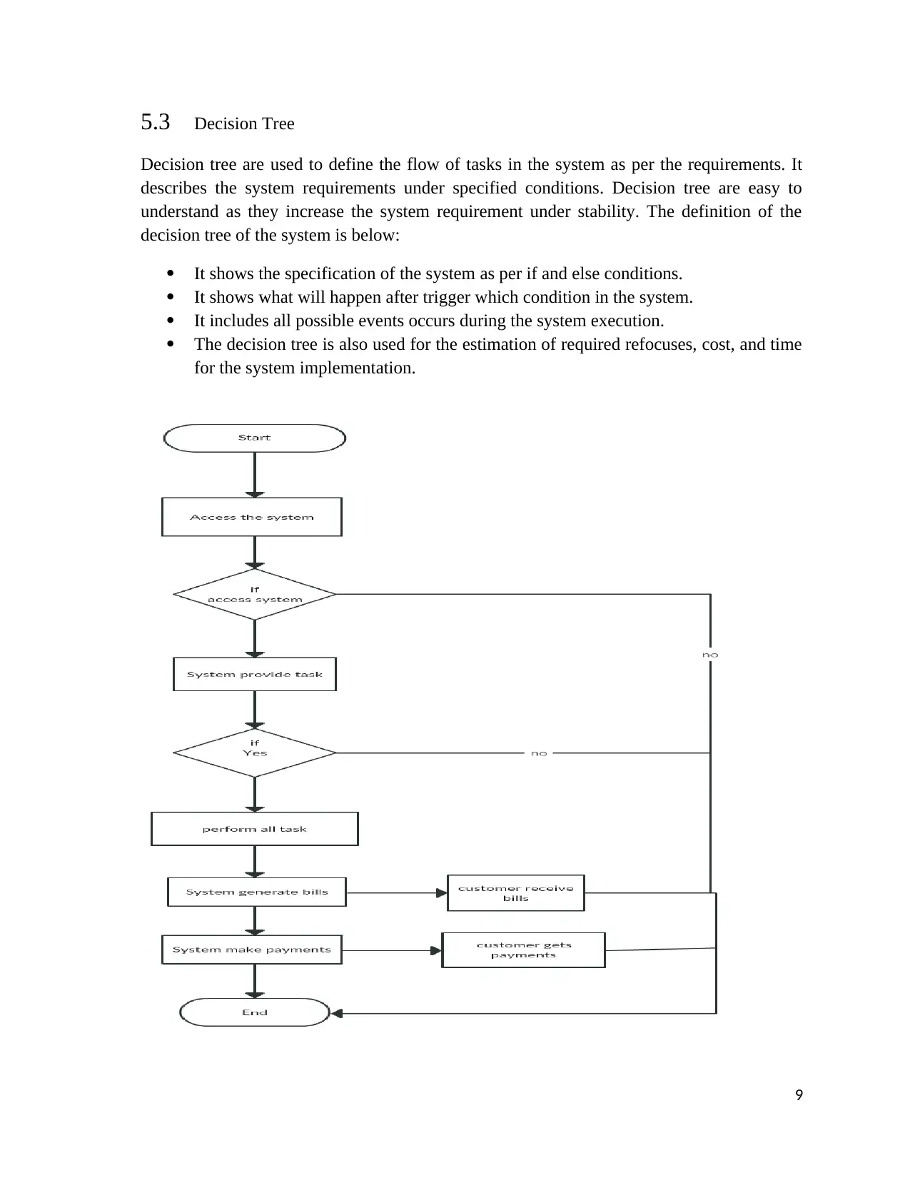
This project analyzes a proposed new billing system for an organization, where the Invoice Department handles customer billing, the Accounts Receivable department manages customer accounts and payments, and the Order and Shipping department provides monthly reports. The project outlines both functional and technical requirements, detailing input, output, and process requirements. It includes security, system control, performance, and business continuity requirements. The project utilizes system context and use case diagrams, data flow diagrams, structured English, decision tables, and decision trees to illustrate the system's design and functionality. The diagrams and models clarify the flow of information, the roles of different departments, and the conditions under which various processes occur. The project aims to improve organizational efficiency, provide comprehensive information, and enhance financial management through the new billing system.
Contribute Materials
Your contribution can guide someone’s learning journey. Share your
documents today.

IFSM
The project is to replace a current billing system with a new billing system in which the customer
billing is handled by the Invoice Department. Customer department are handled by the accounts
1
The project is to replace a current billing system with a new billing system in which the customer
billing is handled by the Invoice Department. Customer department are handled by the accounts
1
Secure Best Marks with AI Grader
Need help grading? Try our AI Grader for instant feedback on your assignments.

receivable department, and customer payments are handled by the accounts receivable
department, which reports to the CFO. Order and shipping department will send a monthly report
to invoicing where the products ordered and shipped and their codes are entered into the
invoicing module.
1. Functional Requirements
1.1 Functional Requirement
Functional requirement are those requirements which shows the functionality of
the system. It shows what is going on not how it is going on.
1.1.1 Output Requirement
The output requirements of the project are as follows:
The system should provide the customer bills.
The system must be able to make payments.
It must contain internal details such as product ordered, product order
date, product shipped, product shipped date, product price, calculated
price.
The system must increase the organization productivity and efficiency.
The system must provide all required information at one place.
The system must provide higher feasibility and generate future
revenue.
The system must sort tasks at one place and makes hierarchy between
the management.
The system must provide the maintenance and records for the large
number of orders.
The system must solve the financial department problem.
1.1.2 Input Requirement
Input requirement of the projects are given as follows:
The system must contain product ordered as input.
It must contain product order date as input.
It must contain Product shipped order as input.
It must contain product shipped date as input.
It must contain the product quantity.
The system must contain the product price as input.
The system should contain the calculated price as input.
The system should take the login id and password as input.
2

1.1.3 Process Requirement
The process requirements of the project are given as follows:
The system should contain some process requirement such as login in
the system.
In the process the system should take all internal details as input
requirement.
In the process the system should calculate all internal details.
In process the system should generate the bills as per the internally
provided details.
In the process the system should make the payments as per the whole
customer details.
2. Technical Requirement
The Technical requirements show the non-functional requirement of the project.
It does not show the functionality. It shows what is technically required to
perform or achieve the functionality. There are definitions of the technical
requirements of the specified system in details which are given as follows:
2.1.1 Security Requirement
The security requirements of the project are given as follows:
The system must follow the all login credentials.
The system must follow the all authentication details.
The system must be secure from the bank details perspective.
The system must be secure from the payment and bills perspectives the
details of bills and payments should not be shown unnecessarily.
2.1.2 System Control Requirement
The system should be functional with full authentication.
It should be in control of management department.
The system should follow the whole organizational policies.
The system must be operated in a fully controlled manner.
2.1.3 Performance Requirement
The data fetching time and execution of the system must be less.
The system must follow all credentials.
The system should perform the whole functions under the specified
conditions.
The system storage capacity should be good.
The system should perform all end-user tasks clearly.
2.1.4 Business Continuity Requirement
3

The system performance of current time should be good for the
business continuity.
The system should increase the business productivity and efficiency of
the organization.
The system should be able to do all functioning properly on time.
The system needs to reduce the ambiguity.
The system needs to increase the future growth of the organization.
The system should keep track of all orders.
The system should be capable in less consumption.
3. System Scope Diagram
3.1 System Context Diagram
The context diagram is a low level data flow diagram which shows how data flows
in the system but it does not include the database such as data flow diagram. The
context diagram defines the boundary between the system, or the part of a system
and its environment. This diagram is the high level view of the system. The context
level diagram is used to show overall functionality of the system. It shows the
entities that interact with it. The context diagram shows the whole input and output
factors of the entities. The context diagram is also similar to the block diagram.
System context diagrams are used early in a project to get an agreement on the
scope. The context diagram below is described as follows:
The system is located at the middle of the diagram.
The management department will access the billing and the payment system.
Then system will provide task for all to the management department.
The order and sales department will provide a monthly report to the Invoice
department.
The invoice department will handle the customers’ bills that are provide by
the system and the invoice department provides details to the billing and
payment system.
The system will generate bills that are received by the customers.
The system will make payments that are also received by the customer.
System records all details at one place for the further use.
4
Secure Best Marks with AI Grader
Need help grading? Try our AI Grader for instant feedback on your assignments.

3.2 System Use Case Diagram
5
5

The use case diagram is used to define to all use cases in the system. The above use case diagram
is defined as follows:
The above use case diagram contains six officials that are as follows – management
department, invoice department, sales department, order department, system admin, and
customer.
Firstly, the management department will access the system and then the system admin
will provide tasks for all to the management department.
Then sales and order department provide monthly details to the invoice department.
Then the system admin provides customer bills for handling to the invoice department.
Invoice department then provide details to the system by system admin.
Then the system will generate the bills.
The customer will receive the system generated bills.
System then makes the payments that are also received by the customer.
6

4. Data Flow Diagram
The data flow diagram is used to shows the data flow in the system. It also includes the database
in the flow of data. The description of above dataflow diagram is described as follows:
Firstly, the management department will access the billing and the payment system.
Then the system will provide task for all to the management department.
System will provide customer bills to the invoice department for handling.
Sales and order department will provide the monthly details to the invoice department.
Then the invoice department will provide the details to the system.
System will generate the bills that are received by the customers.
Then the system will make the payments that are also received by the customers.
Then the system will stores the whole details into the database to the further use.
5. Process Models
5.1 Structure English
The structure English is the additional method which is used for overcoming the
problems of the ambiguous language in stating the actions and conditions in making
the decisions and formulating the procedures. The structure English is like as pseudo
code which defines as follows:
7
Paraphrase This Document
Need a fresh take? Get an instant paraphrase of this document with our AI Paraphraser

1.1.1.1 Management department ACCESS the system.
1.1.1.2 If Access system then,
1.1.1.3 System provide task for all to the management department.
1.1.1.4 Sales and the order department provide monthly details to the invoice
department.
1.1.1.5 System provides customer bills for handling to the invoice department.
1.1.1.6 Invoice department provides details to the system.
1.1.1.7 System will generate bills.
1.1.1.8 Customers will receive the bills.
1.1.1.9 System will generate the payments.
1.1.1.10 Customer will receive the payments.
1.1.1.11 Else
1.1.1.12 System doesn’t work well.
5.2 Decision Table
The decision tables are used to show the requirements or the performance of the
system as per the specified conditions which are described as follows:
Conditions
Management Access System Y N
Invoice Department get bills
Order departments provide detail
Y N
Sales department provide details Y N
System generate bills Y N
System makes payment Y N
Customer get bills Y N
Customer receive payments Y N
The above decision table is described as follows:
There are conditions that are given and the table and action performed based
on the conditions yes or no.
If the management department will access the system then the system will
provide the customer bills to the invoice department and the sales and the
order department will provide the monthly details to the invoice department.
Then the system will generate the bills and the payments.
Then customer will receive the payments and the bills.
If the management department will not access the system then all conditions
will be discarded.
The customer will not get the bills and payments finally in this approach.
8

5.3 Decision Tree
Decision tree are used to define the flow of tasks in the system as per the requirements. It
describes the system requirements under specified conditions. Decision tree are easy to
understand as they increase the system requirement under stability. The definition of the
decision tree of the system is below:
It shows the specification of the system as per if and else conditions.
It shows what will happen after trigger which condition in the system.
It includes all possible events occurs during the system execution.
The decision tree is also used for the estimation of required refocuses, cost, and time
for the system implementation.
9
1 out of 9
Related Documents

Your All-in-One AI-Powered Toolkit for Academic Success.
+13062052269
info@desklib.com
Available 24*7 on WhatsApp / Email
Unlock your academic potential
© 2024 | Zucol Services PVT LTD | All rights reserved.