Mechanical Engineering: Biomass Power Plant Design Report
VerifiedAdded on 2022/10/01
|22
|3333
|46
Report
AI Summary
This report details the design of a 200MW biomass power plant, focusing on a spreader-stoker grate boiler, a sub-critical reheat and regenerative steam cycle, and an evaporative cooling tower. The design adheres to specific criteria including ambient conditions, frequency, power factor, steam pressures and temperatures, turbine efficiencies, and pump efficiencies. The report includes an analysis of fuel characteristics, particularly the ultimate analysis of the biomass fuel. The design methodology utilizes the Rankine cycle for power generation. Key components like the boiler, steam turbine, air condenser, and feed water heater are discussed. The report also addresses the justification for biomass power, considering its environmental benefits and cost-effectiveness compared to fossil fuels. The design incorporates assumptions related to ambient conditions, fuel composition, and component efficiencies. The report also covers the design basis, including the use of dual-fuel fired boilers, and the estimation of biomass power output. The report also includes descriptions of BFB and CFB technologies.
DESIGN OF BIOMASS POWER PLANT 1
Report on The Design of Biomass Power Plant
Name of Student
Institution Affiliation
Report on The Design of Biomass Power Plant
Name of Student
Institution Affiliation
Paraphrase This Document
Need a fresh take? Get an instant paraphrase of this document with our AI Paraphraser
DESIGN OF BIOMASS POWER PLANT 2
Table of Contents
INTRODUCTION...........................................................................................................................3
Justification......................................................................................................................................4
Design basis and methodology........................................................................................................5
Characteristic of fuels..................................................................................................................7
Biomass power.........................................................................................................................8
Biomass conversion.................................................................................................................8
Direct combustion....................................................................................................................9
Steam turbine...........................................................................................................................9
Air condenser...........................................................................................................................9
Feed water heater.....................................................................................................................9
Bubbling fluidized bed BFB..................................................................................................11
Circulating Fluidized Bed......................................................................................................11
Steam cycle design........................................................................................................................12
Process 1-2.............................................................................................................................13
Process 2-3.............................................................................................................................13
Process 3-4.............................................................................................................................13
Process 4-1.............................................................................................................................13
Assumptions on the plant specifications................................................................................14
DESIGN OF BIOMASS POWER PLANT 3
References......................................................................................................................................16
INTRODUCTION
Biomass power production is the conversion and transformation of biomass fuels to produce
energy used run generators to produce electricity or heat. There are two broad techniques for this
conversion depending on the final output, and they are gasification and direct-fired system. In
direct fired system there are sub specific techniques involved in power generation and they
include stoker boilers, cofiring and fluidized bed boilers. Techniques involved in gasification
systems are fluidized bed gasifiers and fixed bed gasifiers (Pode, 2016.)
Most of currently available biomass plants have power output below 50 MW in size and they use
direct fired techniques in their systems. The high pressure steam produced in the boiler by
burning of biomass is used to drive steam turbine which in turn provides a driving mechanism to
the generator producing power output (Sheridan & Murphy, 2017). In most occasions steam for
the process is obtained from the turbine at medium temperature and pressure and are applied in
the space cooling and heating and heat processes. In comparison with cofiring, portion of
biomass is substituted by considerable portion of coal in the boilers to generate power, this
technique is the most economical option for producing biomass power, though it is the near term
possibility to introduce new biomass power production. Cofiring systems are gaining massive
consideration in the current establishment of biomass power generation because unlike the
existing systems cannot work efficiently without modifications to devices and systems, it is less
costly that establishing a new power generation plant. (Yang et al., 2016)
⊘ This is a preview!⊘
Do you want full access?
Subscribe today to unlock all pages.
Trusted by 1+ million students worldwide
DESIGN OF BIOMASS POWER PLANT 4
Justification
Global warming and greenhouse gas effect has been a global challenge for over a decade now
and all authorities and environmental agencies both nationally and internationally are geared
towards finding a long lasting solution will ensure total elimination of these gases that cause
global warming from atmosphere. Yes biomass power generation is the most ideal replacement
of coal power plants since in energy production through biomass there is no emission of toxic
gases such as carbon dioxide, Sulphur oxides and nitrides into the atmosphere (Pang et al., 2017)
Compared to other modes of power generation, for instance coal, resources of biomass are
abundant as there are wide range of inputs ranging from agricultural waste products, vegetables
and forestry (Li et al., 2015). Biomass energy is the only renewable energy form that can easily
be transported from one place to another without much complication and this energy can
conveniently be stored. Biomass power production is the most cost effective compared to other
modes since the resources are abundant and industries such as paper plant and sugar industries
can conveniently use waste by-products of biomass plant as fuel and most authorities offer
subsidiaries to biomass power plants, unlike hydro power production where cost is highly
escalated and water availability is not a guarantee occupies wider space (Heydari & Askarzadeh,
2016).
This project dubbed “Power from Waste” focuses on mega production of energy from biomass
that naturally has the largest portion of global renewable energy and it is gaining popularity in
electricity generation in biomass power plants and in coal through cofiring to reduce on carbon
and Sulphur emission into environment (Sara et al., 2016).
Paraphrase This Document
Need a fresh take? Get an instant paraphrase of this document with our AI Paraphraser
DESIGN OF BIOMASS POWER PLANT 5
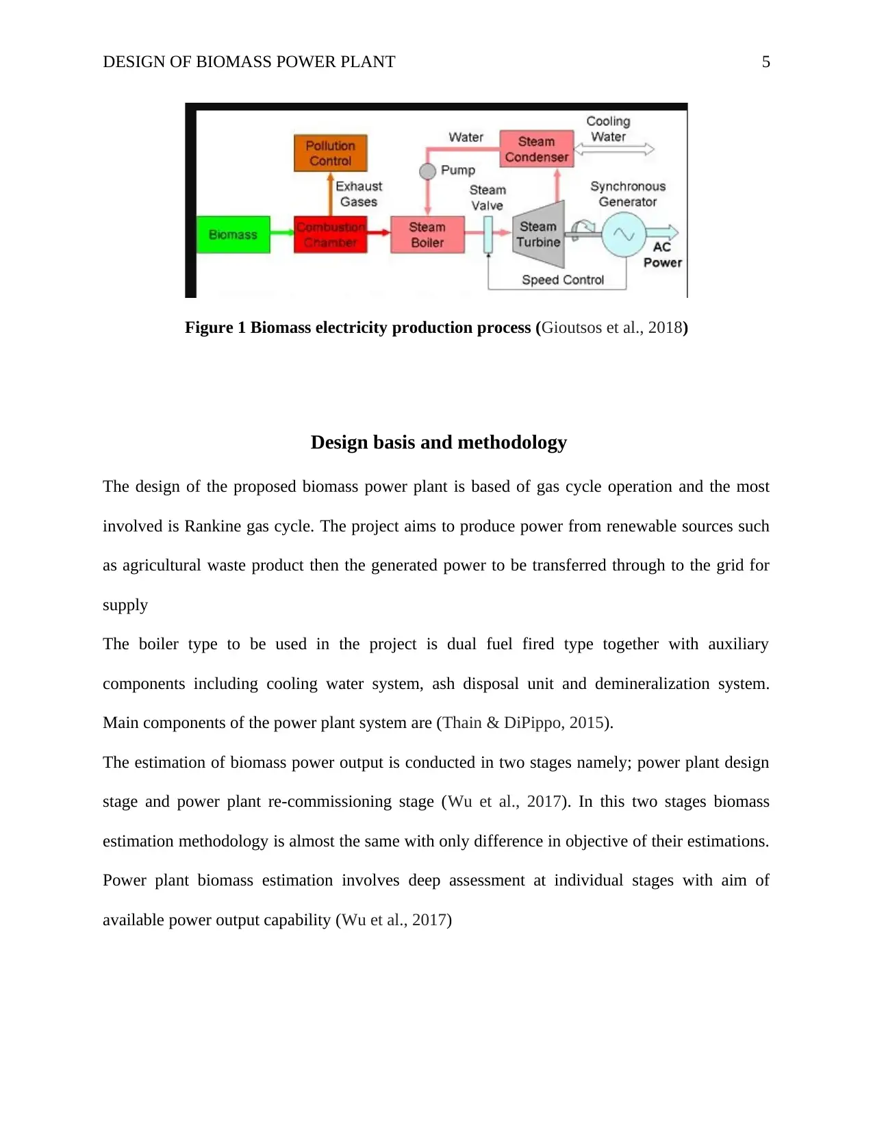
Figure 1 Biomass electricity production process (Gioutsos et al., 2018)
Design basis and methodology
The design of the proposed biomass power plant is based of gas cycle operation and the most
involved is Rankine gas cycle. The project aims to produce power from renewable sources such
as agricultural waste product then the generated power to be transferred through to the grid for
supply
The boiler type to be used in the project is dual fuel fired type together with auxiliary
components including cooling water system, ash disposal unit and demineralization system.
Main components of the power plant system are (Thain & DiPippo, 2015).
The estimation of biomass power output is conducted in two stages namely; power plant design
stage and power plant re-commissioning stage (Wu et al., 2017). In this two stages biomass
estimation methodology is almost the same with only difference in objective of their estimations.
Power plant biomass estimation involves deep assessment at individual stages with aim of
available power output capability (Wu et al., 2017)
DESIGN OF BIOMASS POWER PLANT 6
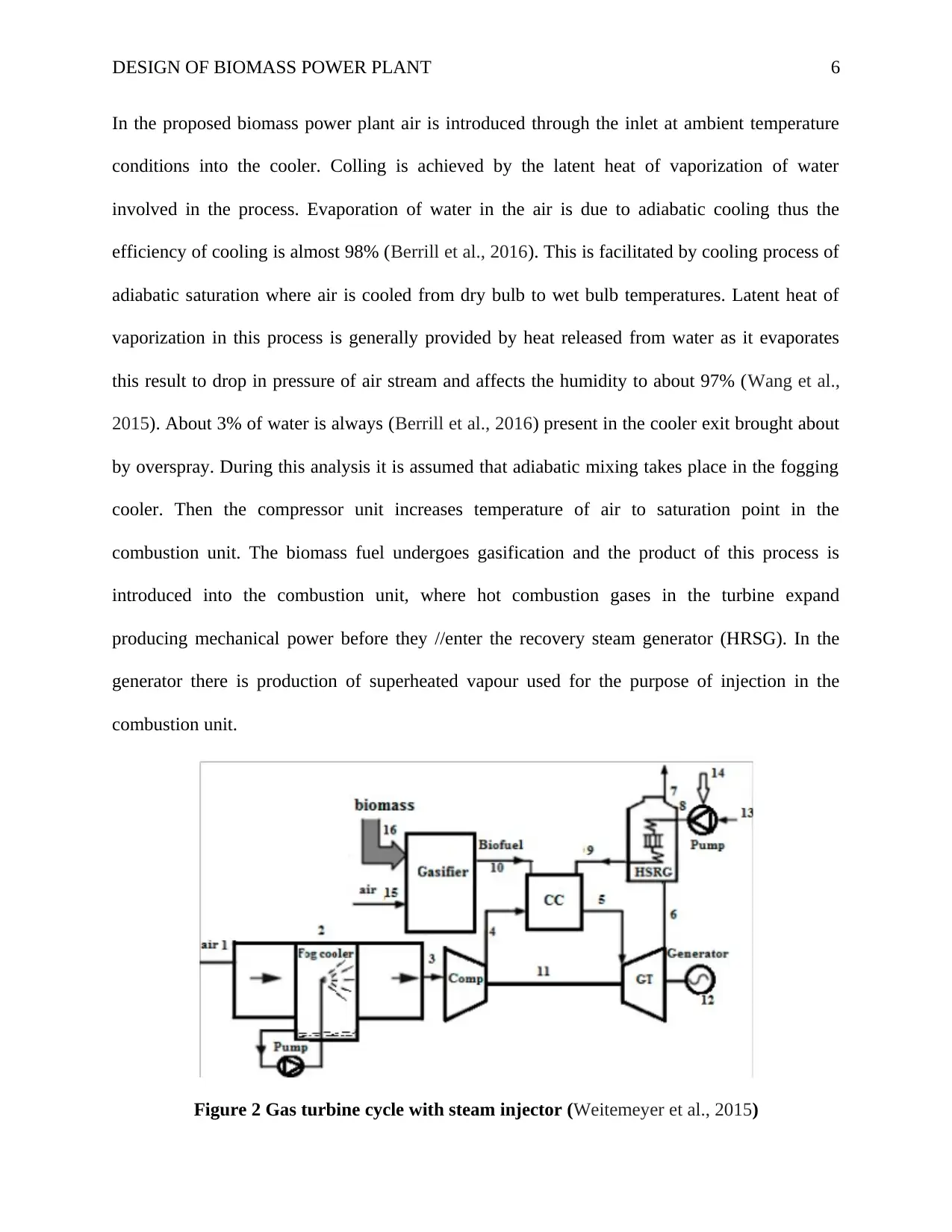
In the proposed biomass power plant air is introduced through the inlet at ambient temperature
conditions into the cooler. Colling is achieved by the latent heat of vaporization of water
involved in the process. Evaporation of water in the air is due to adiabatic cooling thus the
efficiency of cooling is almost 98% (Berrill et al., 2016). This is facilitated by cooling process of
adiabatic saturation where air is cooled from dry bulb to wet bulb temperatures. Latent heat of
vaporization in this process is generally provided by heat released from water as it evaporates
this result to drop in pressure of air stream and affects the humidity to about 97% (Wang et al.,
2015). About 3% of water is always (Berrill et al., 2016) present in the cooler exit brought about
by overspray. During this analysis it is assumed that adiabatic mixing takes place in the fogging
cooler. Then the compressor unit increases temperature of air to saturation point in the
combustion unit. The biomass fuel undergoes gasification and the product of this process is
introduced into the combustion unit, where hot combustion gases in the turbine expand
producing mechanical power before they //enter the recovery steam generator (HRSG). In the
generator there is production of superheated vapour used for the purpose of injection in the
combustion unit.
Figure 2 Gas turbine cycle with steam injector (Weitemeyer et al., 2015)
⊘ This is a preview!⊘
Do you want full access?
Subscribe today to unlock all pages.
Trusted by 1+ million students worldwide
DESIGN OF BIOMASS POWER PLANT 7
Assumptions considered in this process are
The ambient pressure, which is the inlet air, is at atmospheric conditions P1=1.013 bar
temperature T1= 283K and φamb = 60%
Composition of air is at 78% nitrogen and 21% oxygen by volume percentage.
Polytrophic efficiency of turbine and compressor are equal at 18%, isentropic efficiency of the
pump is at 8%
Gravimetric composition of dry biomass is at 6% hydrogen. 50% carbon dioxide and 44%
oxygen gas with calorific value of 450,576
KJ/kmol, moisture content of the biomass is at 20% of the total mass and equivalent gasification
ratio is at 0.420
Steam pressure of HRSG is at 79 bars, temperature difference of HRSG is at 50K and the pinch
point boiler temperature difference is at 283K
The combustion of biomass and fuel is full combustion and the chamber is adiabatic with
pressure drop of 1%
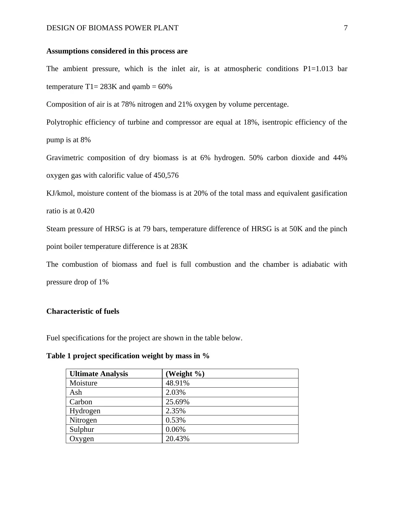
Characteristic of fuels
Fuel specifications for the project are shown in the table below.
Table 1 project specification weight by mass in %
Ultimate Analysis (Weight %)
Moisture 48.91%
Ash 2.03%
Carbon 25.69%
Hydrogen 2.35%
Nitrogen 0.53%
Sulphur 0.06%
Oxygen 20.43%
Assumptions considered in this process are
The ambient pressure, which is the inlet air, is at atmospheric conditions P1=1.013 bar
temperature T1= 283K and φamb = 60%
Composition of air is at 78% nitrogen and 21% oxygen by volume percentage.
Polytrophic efficiency of turbine and compressor are equal at 18%, isentropic efficiency of the
pump is at 8%
Gravimetric composition of dry biomass is at 6% hydrogen. 50% carbon dioxide and 44%
oxygen gas with calorific value of 450,576
KJ/kmol, moisture content of the biomass is at 20% of the total mass and equivalent gasification
ratio is at 0.420
Steam pressure of HRSG is at 79 bars, temperature difference of HRSG is at 50K and the pinch
point boiler temperature difference is at 283K
The combustion of biomass and fuel is full combustion and the chamber is adiabatic with
pressure drop of 1%
Characteristic of fuels
Fuel specifications for the project are shown in the table below.
Table 1 project specification weight by mass in %
Ultimate Analysis (Weight %)
Moisture 48.91%
Ash 2.03%
Carbon 25.69%
Hydrogen 2.35%
Nitrogen 0.53%
Sulphur 0.06%
Oxygen 20.43%
Paraphrase This Document
Need a fresh take? Get an instant paraphrase of this document with our AI Paraphraser
DESIGN OF BIOMASS POWER PLANT 8
Higher heating value HHP of biomass fuel and LHP pf the coal are calculated as follows
Biomass power
Biomass is commonly referred to as organic matter and are directly produced or sometimes
indirectly from organisms without contamination. Most common sources of biomass are wood
and wood waste agricultural crops and wastes, mill residue, municipal wastes . livestock wastes
and industrial wastes. Estimation from recent research shows that biomass if rank third in energy
sources, providing approximately 20% (Rao et al., 2017) of the total energy requirement in the
world, with about 40% of biomass is consumed in rural areas in developing countries. This big
margin is because the sources of biomass energy are abundantly available in such areas. The
conversion of biomass energy to electric power is quite simple and does not require a lot of fund
to start and run. It is the only fuel for renewable combustion for power generation plants. This
has made it of more preference to fossil fuels (Rahmati et al., 2018).
Biomass conversion
There developed techniques for conversion of bio power of renewable biomass into electricity in
various ways, of the many techniques three are the ones commonly used, these are direct
combustion, pyrolysis and gasification. Each of these techniques has seen numerous adjustments
thus also have sub techniques of operations
Direct combustion
Direct combustion is the majorly used technique in biomass electricity generation, involving
direct combustion process. It involves direct burning of biomass in the boiler to produce steam
DESIGN OF BIOMASS POWER PLANT 9
which is used to rotate turbines connected to generator that produces electricity (Sara et al.,
2016).
Steam turbine
Steam turbine facilitates the generation of power by proving driving mechanisms to power
generators. The design propose that the steam turbines to have high pressure stage that operates
between inlet steam pressure where controlled extraction will allow the removal of small portion
of steam for reheating feed water. Then the low pressure turbine stage will facilitate the
expansion of the remaining steam from turbine pressure to condenser pressure conditions
The turbine drive shafts are adjusted and coupled to generator that produces electricity that is
eventually supplied to main grid (Yang et al., 2016).
Air condenser
Condensers enhances the cooling of hot air to ambient condition, as saturated steam leaves the
turbine generator that are condensed in the condenser to the required temperature, air cooled
condenser needs less water compared to cooling towers or evaporative systems. Because of this
reason air cooled condenser is the most appropriate for these power plant
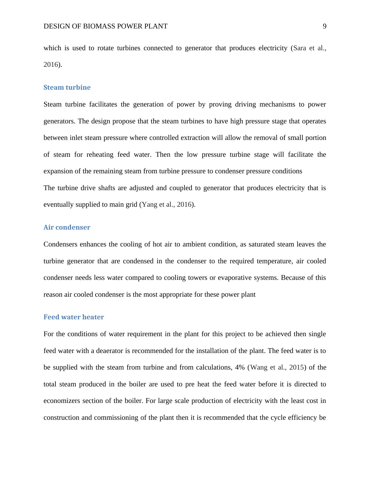
Feed water heater
For the conditions of water requirement in the plant for this project to be achieved then single
feed water with a deaerator is recommended for the installation of the plant. The feed water is to
be supplied with the steam from turbine and from calculations, 4% (Wang et al., 2015) of the
total steam produced in the boiler are used to pre heat the feed water before it is directed to
economizers section of the boiler. For large scale production of electricity with the least cost in
construction and commissioning of the plant then it is recommended that the cycle efficiency be
which is used to rotate turbines connected to generator that produces electricity (Sara et al.,
2016).
Steam turbine
Steam turbine facilitates the generation of power by proving driving mechanisms to power
generators. The design propose that the steam turbines to have high pressure stage that operates
between inlet steam pressure where controlled extraction will allow the removal of small portion
of steam for reheating feed water. Then the low pressure turbine stage will facilitate the
expansion of the remaining steam from turbine pressure to condenser pressure conditions
The turbine drive shafts are adjusted and coupled to generator that produces electricity that is
eventually supplied to main grid (Yang et al., 2016).
Air condenser
Condensers enhances the cooling of hot air to ambient condition, as saturated steam leaves the
turbine generator that are condensed in the condenser to the required temperature, air cooled
condenser needs less water compared to cooling towers or evaporative systems. Because of this
reason air cooled condenser is the most appropriate for these power plant
Feed water heater
For the conditions of water requirement in the plant for this project to be achieved then single
feed water with a deaerator is recommended for the installation of the plant. The feed water is to
be supplied with the steam from turbine and from calculations, 4% (Wang et al., 2015) of the
total steam produced in the boiler are used to pre heat the feed water before it is directed to
economizers section of the boiler. For large scale production of electricity with the least cost in
construction and commissioning of the plant then it is recommended that the cycle efficiency be
⊘ This is a preview!⊘
Do you want full access?
Subscribe today to unlock all pages.
Trusted by 1+ million students worldwide
DESIGN OF BIOMASS POWER PLANT 10
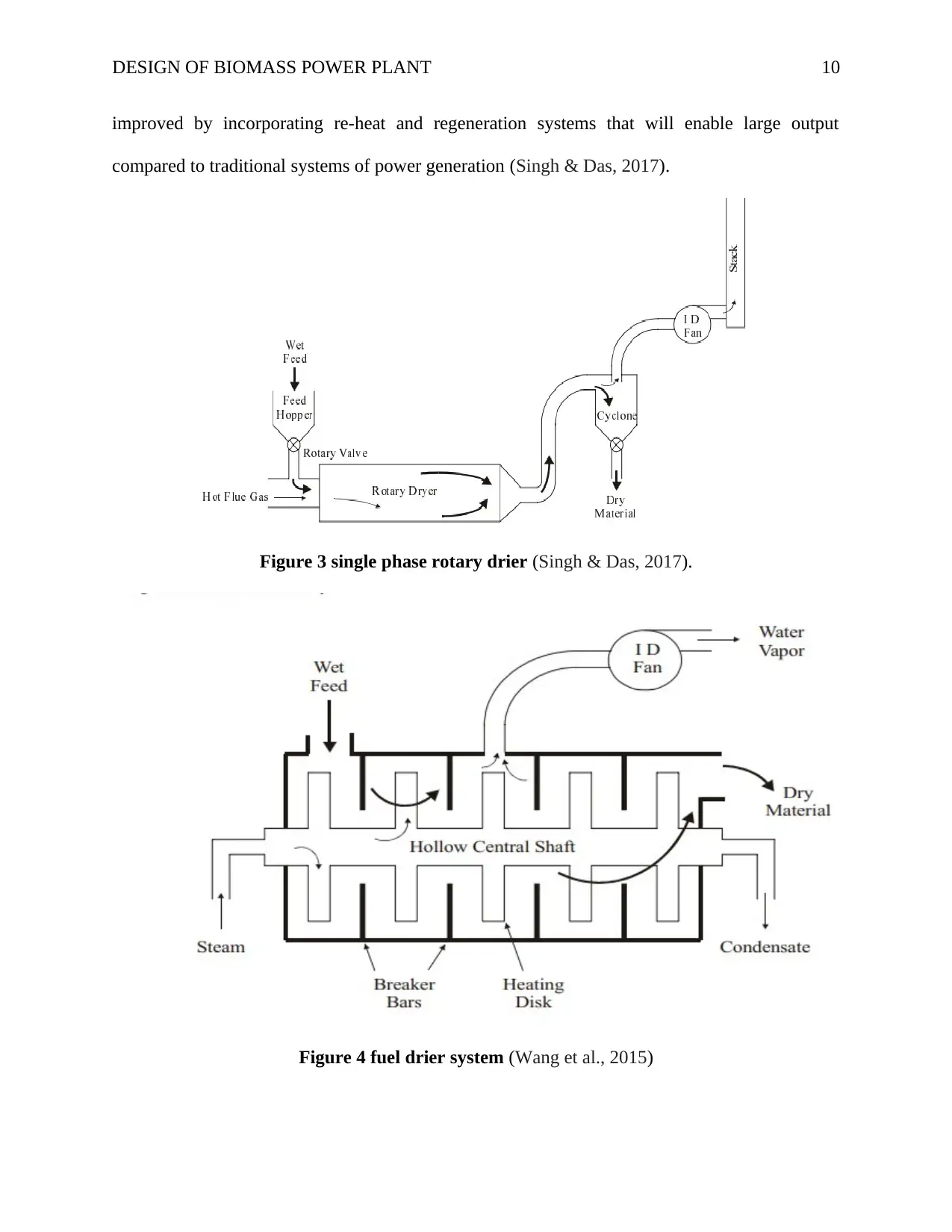
improved by incorporating re-heat and regeneration systems that will enable large output
compared to traditional systems of power generation (Singh & Das, 2017).
Figure 3 single phase rotary drier (Singh & Das, 2017).
Figure 4 fuel drier system (Wang et al., 2015)
improved by incorporating re-heat and regeneration systems that will enable large output
compared to traditional systems of power generation (Singh & Das, 2017).
Figure 3 single phase rotary drier (Singh & Das, 2017).
Figure 4 fuel drier system (Wang et al., 2015)
Paraphrase This Document
Need a fresh take? Get an instant paraphrase of this document with our AI Paraphraser
DESIGN OF BIOMASS POWER PLANT 11
Bubbling fluidized bed BFB
The main core of the bubbling fluidized bed is located in the combustion chamber or furnace
where it has water cooled walls, bottom lining has installed refractory linings (Singh & Das,
2017). The fluidization is obtained by arranging nozzles at the lower section of the furnace; these
arrangements create turbulence that enhances the mixing of combustion fuels and their
conversion inti char, the provision of well stirred bed allows settlement of soli materials blocking
them from entering freeboard region.
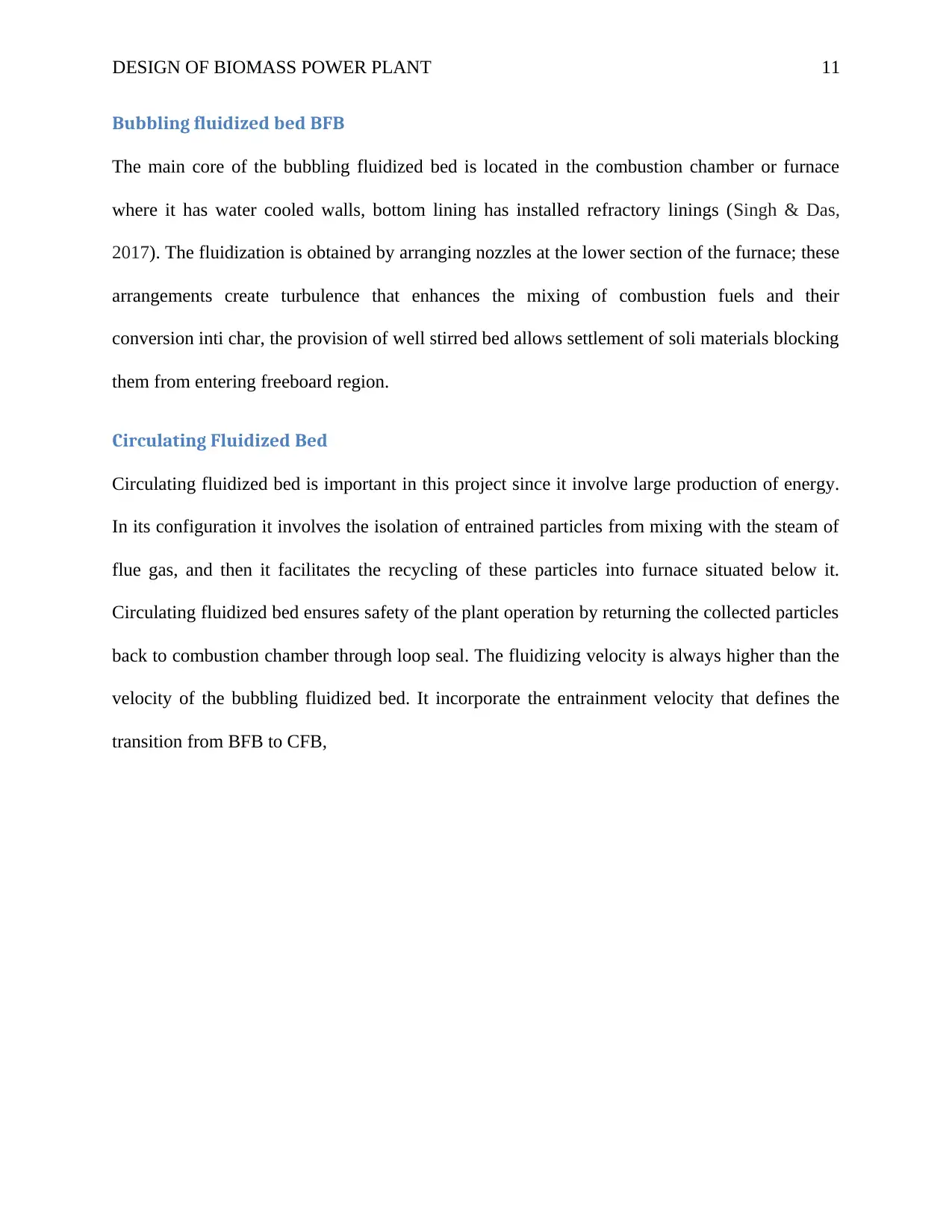
Circulating Fluidized Bed
Circulating fluidized bed is important in this project since it involve large production of energy.
In its configuration it involves the isolation of entrained particles from mixing with the steam of
flue gas, and then it facilitates the recycling of these particles into furnace situated below it.
Circulating fluidized bed ensures safety of the plant operation by returning the collected particles
back to combustion chamber through loop seal. The fluidizing velocity is always higher than the
velocity of the bubbling fluidized bed. It incorporate the entrainment velocity that defines the
transition from BFB to CFB,
Bubbling fluidized bed BFB
The main core of the bubbling fluidized bed is located in the combustion chamber or furnace
where it has water cooled walls, bottom lining has installed refractory linings (Singh & Das,
2017). The fluidization is obtained by arranging nozzles at the lower section of the furnace; these
arrangements create turbulence that enhances the mixing of combustion fuels and their
conversion inti char, the provision of well stirred bed allows settlement of soli materials blocking
them from entering freeboard region.
Circulating Fluidized Bed
Circulating fluidized bed is important in this project since it involve large production of energy.
In its configuration it involves the isolation of entrained particles from mixing with the steam of
flue gas, and then it facilitates the recycling of these particles into furnace situated below it.
Circulating fluidized bed ensures safety of the plant operation by returning the collected particles
back to combustion chamber through loop seal. The fluidizing velocity is always higher than the
velocity of the bubbling fluidized bed. It incorporate the entrainment velocity that defines the
transition from BFB to CFB,
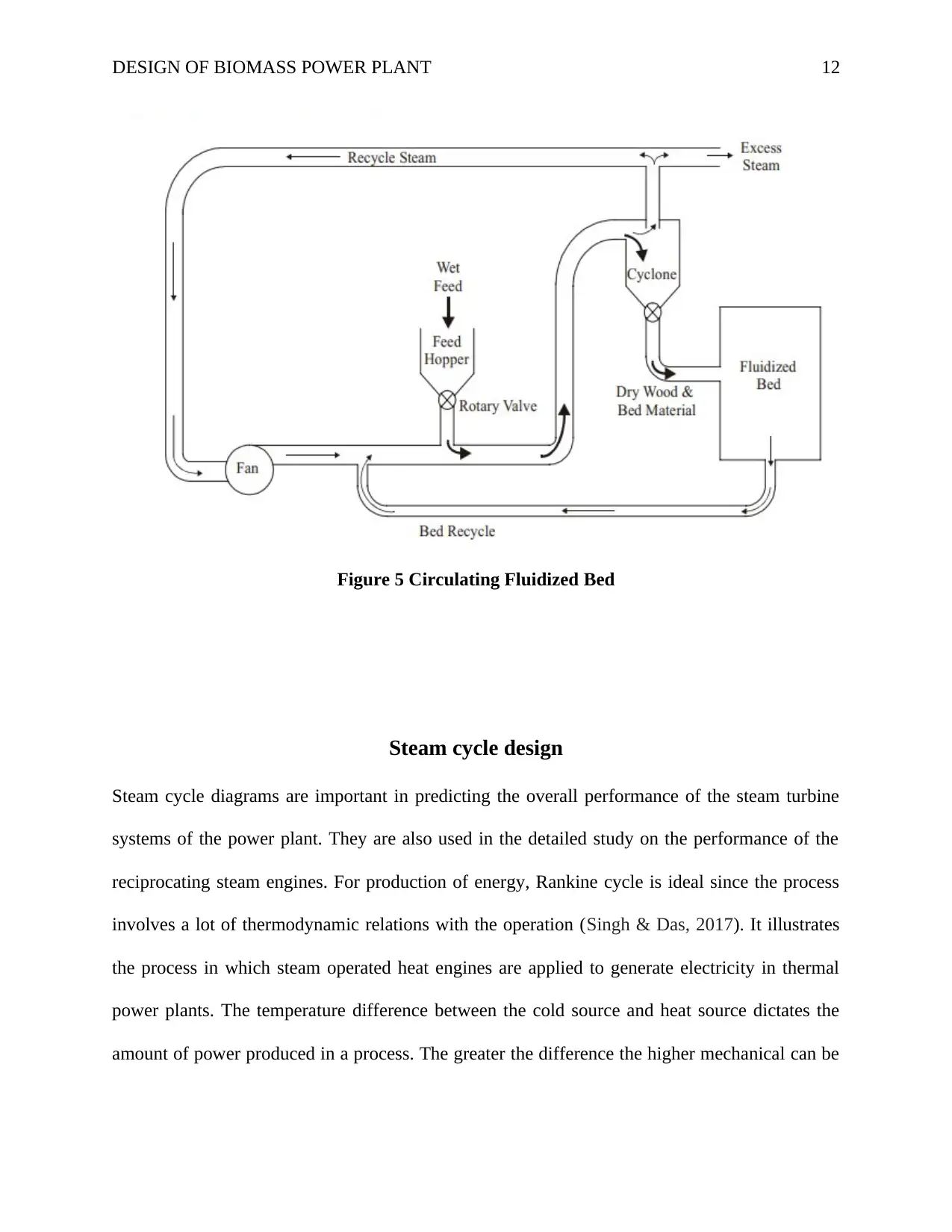
DESIGN OF BIOMASS POWER PLANT 12
Figure 5 Circulating Fluidized Bed
Steam cycle design
Steam cycle diagrams are important in predicting the overall performance of the steam turbine
systems of the power plant. They are also used in the detailed study on the performance of the
reciprocating steam engines. For production of energy, Rankine cycle is ideal since the process
involves a lot of thermodynamic relations with the operation (Singh & Das, 2017). It illustrates
the process in which steam operated heat engines are applied to generate electricity in thermal
power plants. The temperature difference between the cold source and heat source dictates the
amount of power produced in a process. The greater the difference the higher mechanical can be
⊘ This is a preview!⊘
Do you want full access?
Subscribe today to unlock all pages.
Trusted by 1+ million students worldwide
1 out of 22
Related Documents


Your All-in-One AI-Powered Toolkit for Academic Success.
+13062052269
info@desklib.com
Available 24*7 on WhatsApp / Email
![[object Object]](/_next/static/media/star-bottom.7253800d.svg)
Unlock your academic potential
Copyright © 2020–2026 A2Z Services. All Rights Reserved. Developed and managed by ZUCOL.