Higher Diploma in Biomedical Engineering: ECG System Interim Report
VerifiedAdded on 2022/08/27
|28
|5438
|21
Report
AI Summary
This interim report details a Higher Diploma in Biomedical Engineering final project focused on a microcontroller-based personal ECG system. The report includes an abstract, table of contents, and four chapters. Chapter 1 introduces the project's background, problem identification (elderly health monitoring), aim (continuous patient vital measurement), objectives (wireless biosensor, emergency alarm), scope, and limitations. Chapter 2 covers background study, ECG detection algorithms, and ECG signal filters. Chapter 3 provides a literature review of ECG circuitry (amplifiers, instrumentation amplifiers, electrodes, biosensors, filtering techniques, A/D conversion, transmitters), data processing (microcontrollers), output methods (LCD), and emergency alarm systems. Chapter 4 outlines the methodology, including the design overview, ECG circuitry, microcontroller integration, and sensor integration (thermal and pressure), and the emergency alarm system. The project aims to continuously monitor patient vitals, detect heart abnormalities, and provide an emergency alert system, enhancing patient safety and simplifying daily routines. The report references multiple sources and discusses the challenges and considerations involved in the design and implementation of the system.
1
HIGHER DIPLOMA IN BIOMEDICAL ENGINEERING
HND FINAL ENGINEERING PROJECT: INTERIM REPORT
S
Eman Hassan CL/HNDBME/07/25
Varsha Kalubowila CL/HNDBME/07/26
Naween Dissanayake CL/HNDBME/07/05
Adisha Gamage CL/HNDBME/07/18
HIGHER DIPLOMA IN BIOMEDICAL ENGINEERING
HND FINAL ENGINEERING PROJECT: INTERIM REPORT
S
Eman Hassan CL/HNDBME/07/25
Varsha Kalubowila CL/HNDBME/07/26
Naween Dissanayake CL/HNDBME/07/05
Adisha Gamage CL/HNDBME/07/18
Paraphrase This Document
Need a fresh take? Get an instant paraphrase of this document with our AI Paraphraser

Abstract:
2
2
Table of Contents
Chapter 01: Introduction.......................................................................................................................4
1.1 Background of the project:..............................................................................................................4
1.2 Problem identification.....................................................................................................................5
1.3 Aim and Objective...........................................................................................................................5
1.3.1 Aim.......................................................................................................................................5
1.3.2 Objectives.............................................................................................................................5
1.4 Scope and Limitation.......................................................................................................................6
Chapter 02: Background Study.............................................................................................................7
2.0 Theory.............................................................................................................................................7
2.1 ECG Detection Algorithms.....................................................................................................7
2.2 ECG Signal Filters...................................................................................................................8
Chapter 03: Literature Review..............................................................................................................9
3.1 ECG Circuitry..................................................................................................................................9
3.1.1 ECG Amplifier.....................................................................................................................9
3.1.2 Instrumentation Amplifier..................................................................................................11
3.1.3 Electrode.............................................................................................................................11
3.1.4 Biosensors..........................................................................................................................11
3.1.5 Pulse Sensor SEN-11574....................................................................................................12
3.1.6 ECG Filtering Techniques..................................................................................................12
3.1.7 A/D Conversion..................................................................................................................12
3.1.8 Transmitter.........................................................................................................................12
3.2 Data Processing.............................................................................................................................12
3.2.1 Microcontrollers.................................................................................................................12
3.3 Output............................................................................................................................................12
3.3.1 LCD....................................................................................................................................12
3.4 Emergency Alarm System.............................................................................................................12
Chapter 04: Methodology....................................................................................................................13
4.1 Overview of the design..................................................................................................................13
4.2 ECG Circuitry................................................................................................................................14
3
⊘ This is a preview!⊘
Do you want full access?
Subscribe today to unlock all pages.
Trusted by 1+ million students worldwide

4.3 Device to embed Microcontroller..................................................................................................15
4.4 Microcontroller..............................................................................................................................15
4.5 Thermal Sensor..............................................................................................................................15
4.6 Pressure Sensor..............................................................................................................................15
4.7 Emergency Alarm System.............................................................................................................16
4.8 Further Discussion on the Reviewed Project................................................................................16
REFERENCES....................................................................................................................................17
4
Paraphrase This Document
Need a fresh take? Get an instant paraphrase of this document with our AI Paraphraser
Chapter 01: INTRODUCTION
1.1 Background of the project:
An ECG is a recording of the electrical activity on the body surface generated by the heart
aaccording to National Health Service, United Kingdom in 2018, ECG measurement is an
information that is collected through electrodes placed at designated locations on the body. It is the
best way to measure and diagnose abnormal rhythms of the heart, particularly abnormal rhythms
caused by damage to the conductive tissue that carries electrical signals by electrolyte imbalances.
The aim of ECG detection algorithm is to detect the characteristic waveforms of ECG, such as QRS
wave group which represents depolarization and contractions left and right ventricles. This includes
exporting the digitized data of ECG and then using programming languages to detect the high peak
QRS wave group through a threshold.
The National Heart, Lung, and Blood Institute, Disease and Condition Index in 2003, states that
abnormal ECG waveforms are mostly obtained from patients above 55 years old. Therefore senior
citizens are vulnerable to heart attack. Senior citizens need to be monitored closely to identify and be
alerted regarding any sudden changes on the heart condition so that necessary actions could be
taken. Usually a caretaker or a family member is responsible for measuring and recording the
important parameters and comparing them to see if the heart condition worsens or not. This requires
the caretaker/family member to be present near the patient at most times and the elder citizen may
even find it difficult to have to take ECG and such hourly every day. This will definitely hinder their
5
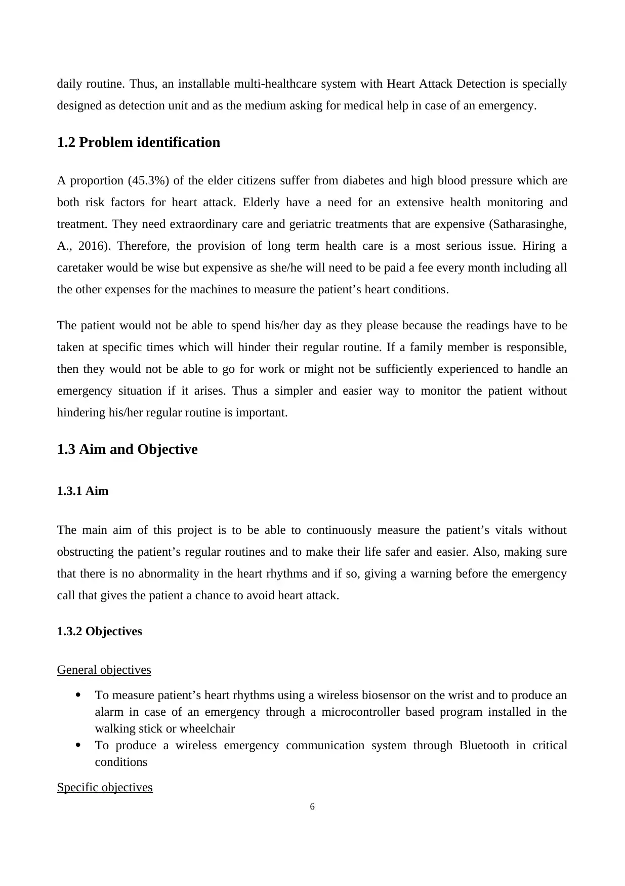
Electrical disease Circulatory disease Structural disease
Problems with the electrical
system that regulates the
steady heartbeats cause heart
rate to be too slow or too fast.
High blood pressure and
coronary artery disease can
cause a stroke or heart attack
Heat muscle disease and
congenital abnormalities are two
problems that can damage the
heart muscle or valves.
1.1 Background of the project:
An ECG is a recording of the electrical activity on the body surface generated by the heart
aaccording to National Health Service, United Kingdom in 2018, ECG measurement is an
information that is collected through electrodes placed at designated locations on the body. It is the
best way to measure and diagnose abnormal rhythms of the heart, particularly abnormal rhythms
caused by damage to the conductive tissue that carries electrical signals by electrolyte imbalances.
The aim of ECG detection algorithm is to detect the characteristic waveforms of ECG, such as QRS
wave group which represents depolarization and contractions left and right ventricles. This includes
exporting the digitized data of ECG and then using programming languages to detect the high peak
QRS wave group through a threshold.
The National Heart, Lung, and Blood Institute, Disease and Condition Index in 2003, states that
abnormal ECG waveforms are mostly obtained from patients above 55 years old. Therefore senior
citizens are vulnerable to heart attack. Senior citizens need to be monitored closely to identify and be
alerted regarding any sudden changes on the heart condition so that necessary actions could be
taken. Usually a caretaker or a family member is responsible for measuring and recording the
important parameters and comparing them to see if the heart condition worsens or not. This requires
the caretaker/family member to be present near the patient at most times and the elder citizen may
even find it difficult to have to take ECG and such hourly every day. This will definitely hinder their
5
Electrical disease Circulatory disease Structural disease
Problems with the electrical
system that regulates the
steady heartbeats cause heart
rate to be too slow or too fast.
High blood pressure and
coronary artery disease can
cause a stroke or heart attack
Heat muscle disease and
congenital abnormalities are two
problems that can damage the
heart muscle or valves.
daily routine. Thus, an installable multi-healthcare system with Heart Attack Detection is specially
designed as detection unit and as the medium asking for medical help in case of an emergency.
1.2 Problem identification
A proportion (45.3%) of the elder citizens suffer from diabetes and high blood pressure which are
both risk factors for heart attack. Elderly have a need for an extensive health monitoring and
treatment. They need extraordinary care and geriatric treatments that are expensive (Satharasinghe,
A., 2016). Therefore, the provision of long term health care is a most serious issue. Hiring a
caretaker would be wise but expensive as she/he will need to be paid a fee every month including all
the other expenses for the machines to measure the patient’s heart conditions.
The patient would not be able to spend his/her day as they please because the readings have to be
taken at specific times which will hinder their regular routine. If a family member is responsible,
then they would not be able to go for work or might not be sufficiently experienced to handle an
emergency situation if it arises. Thus a simpler and easier way to monitor the patient without
hindering his/her regular routine is important.
1.3 Aim and Objective
1.3.1 Aim
The main aim of this project is to be able to continuously measure the patient’s vitals without
obstructing the patient’s regular routines and to make their life safer and easier. Also, making sure
that there is no abnormality in the heart rhythms and if so, giving a warning before the emergency
call that gives the patient a chance to avoid heart attack.
1.3.2 Objectives
General objectives
To measure patient’s heart rhythms using a wireless biosensor on the wrist and to produce an
alarm in case of an emergency through a microcontroller based program installed in the
walking stick or wheelchair
To produce a wireless emergency communication system through Bluetooth in critical
conditions
Specific objectives
6
⊘ This is a preview!⊘
Do you want full access?
Subscribe today to unlock all pages.
Trusted by 1+ million students worldwide
To make the microcontroller programmed to run an algorithm on the received signal to make
sure if there is an abnormality or not
To be able to manually design Microcontroller’s algorithm for each person as their average
heart rate and such is different from one another
To lower total power consumption so battery does not need to be changed often
To give an emergency call to the necessary personnel if situation is critical.
To connect the microcontroller to the phone through Bluetooth so the emergency call can be
given by the phone
1.4 Scope and Limitation
Scope:
The heart rhythms measured by biosensor
Heart rate and contact details shown in LCD of the walking stick or wheelchair
Comparing the heart rate measured to the normal ranges of the patient
Give out necessary signal or emergency call in case of alarming heart abnormalitiess
Limitation:
In practical scenarios, the patient’s phone is used to call and assumption is made that the user is
within the range of the stick or the wheelchair so the Bluetooth signal could not be interfered
The bio-sensors may have less noise cancellation effect depending on the environment of the
patient.
It will be moderately expensive so not everyone who needs it will be able to buy.
7
Paraphrase This Document
Need a fresh take? Get an instant paraphrase of this document with our AI Paraphraser
Chapter 02: BACKGROUND STUDY
2.0 Theory
National Health Service, United Kingdom in 2018 states that the volume of Electrocardiogram
(ECG) recorded in hospitals is increasing as the people suffering from heart diseases are increasing
at an alarming rate. An ECG is a recording of the electrical activity on the body surface generated by
the heart. ECG measurement information is collected by electrodes placed at designated locations on
the body. It is the best way to measure and diagnose abnormal rhythms of the heart, particularly
abnormal rhythms caused by damage to the conductive tissue that carries electrical signals, or
abnormal rhythms caused by electrolyte imbalances. In a Myocardial infarction (MI), the ECG can
identify if the heart muscle has been damaged in specific areas.
2.1 ECG Detection Algorithms
According to 2019 4th International Workshop on Materials Engineering and Computer Sciences,
ECG detection algorithm as an example, the aim of this algorithm is to detect the characteristic
waveforms of ECG, such as QRS wave group representing depolarization of ventricles or
contraction of left and right ventricles. According to the common method, the first way is exporting
the digitized data of ECG, then program using the C ++ language or other programming languages,
at last we can detect the high peak QRS wave group through a threshold.
According to 2019, 4th International Workshop on Materials Engineering and Computer Sciences;
the accuracy of QRS detection based on the above intuitive method is not high. Because the ECG
waveform may be disturbed by EMG, motion, noise and the baseline drift, leading to some QRS
waves far higher or lower than the baseline. It may not be judged on the threshold, or even be
covered by noise. In addition, the threshold changes by the changes of QRS complex according to
some arrhythmias such as ventricular premature beats occur. Therefore, it is needed to consider
improving the detection algorithm, so we need to add many programming methods and strategies.
The core element embodied in these methods and strategies is the basic knowledge of association.
8
2.2 ECG Signal Filters
ECG signal is very sensitive in nature, hence even a small noise such as muscle movements, mains
current and electromagnetic mixed with the original signal can cause a significant change in the final
result. The ECG signal voltage usually ranges from 0.5-5mV and artefacts lager than that can cause
a change in the signal. Data corrupted with noise must either filter or discarded.
The main types of artefact in ECG signal are Power line interference, Muscle contractions, Electrode
contact noise, Motion Artefacts, Baseline wandering, Noise generated by electronic devices used in
signal processing circuits, Electrical interference external to the subject and recording system, High-
frequency noises in the ECG, Breath, lung, or bowel sounds contaminating the heart sounds.
9
⊘ This is a preview!⊘
Do you want full access?
Subscribe today to unlock all pages.
Trusted by 1+ million students worldwide
Chapter 03: LITERATURE REVIEW
3.1 ECG Circuitry
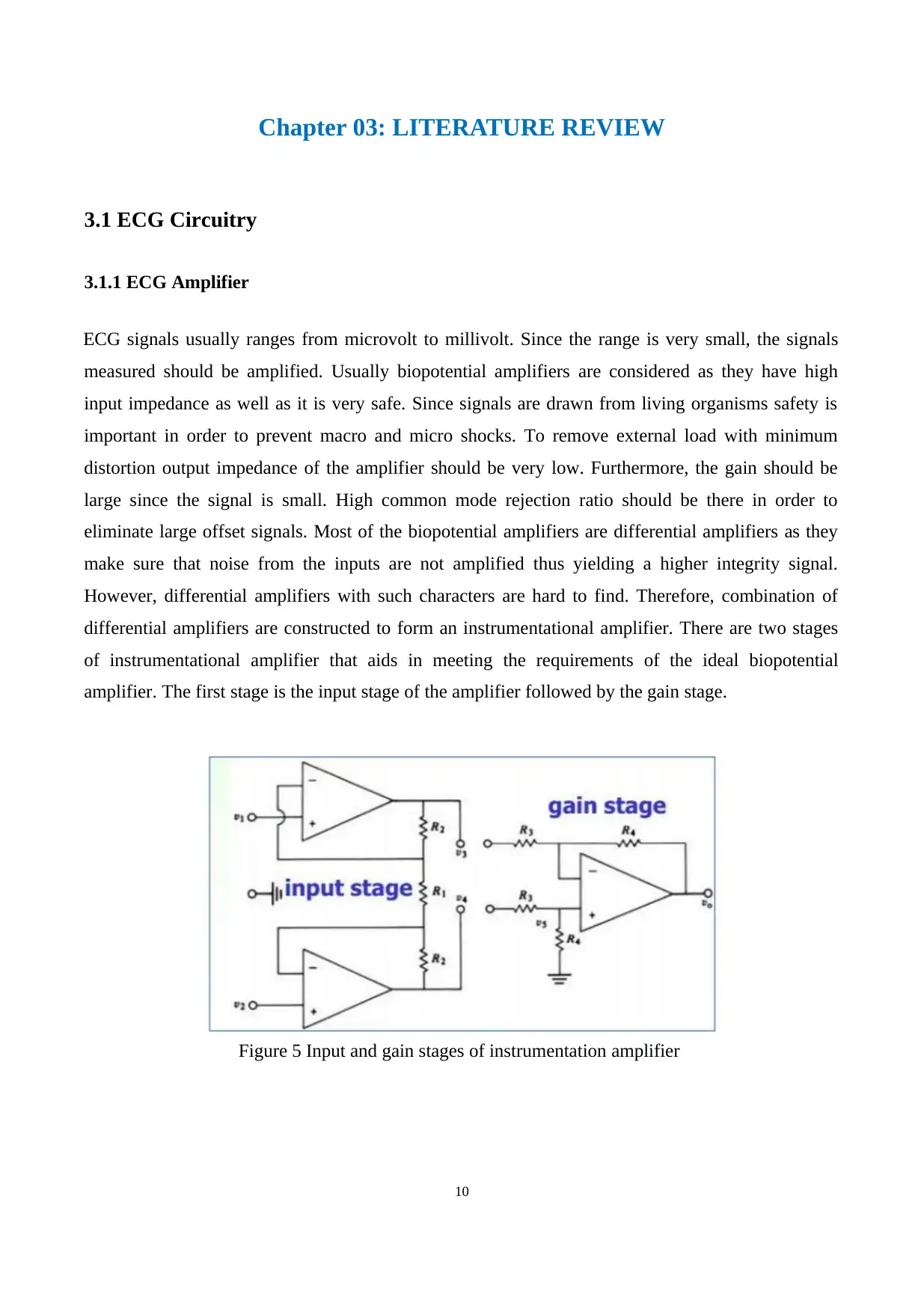
3.1.1 ECG Amplifier
ECG signals usually ranges from microvolt to millivolt. Since the range is very small, the signals
measured should be amplified. Usually biopotential amplifiers are considered as they have high
input impedance as well as it is very safe. Since signals are drawn from living organisms safety is
important in order to prevent macro and micro shocks. To remove external load with minimum
distortion output impedance of the amplifier should be very low. Furthermore, the gain should be
large since the signal is small. High common mode rejection ratio should be there in order to
eliminate large offset signals. Most of the biopotential amplifiers are differential amplifiers as they
make sure that noise from the inputs are not amplified thus yielding a higher integrity signal.
However, differential amplifiers with such characters are hard to find. Therefore, combination of
differential amplifiers are constructed to form an instrumentational amplifier. There are two stages
of instrumentational amplifier that aids in meeting the requirements of the ideal biopotential
amplifier. The first stage is the input stage of the amplifier followed by the gain stage.
Figure 5 Input and gain stages of instrumentation amplifier
10
3.1 ECG Circuitry
3.1.1 ECG Amplifier
ECG signals usually ranges from microvolt to millivolt. Since the range is very small, the signals
measured should be amplified. Usually biopotential amplifiers are considered as they have high
input impedance as well as it is very safe. Since signals are drawn from living organisms safety is
important in order to prevent macro and micro shocks. To remove external load with minimum
distortion output impedance of the amplifier should be very low. Furthermore, the gain should be
large since the signal is small. High common mode rejection ratio should be there in order to
eliminate large offset signals. Most of the biopotential amplifiers are differential amplifiers as they
make sure that noise from the inputs are not amplified thus yielding a higher integrity signal.
However, differential amplifiers with such characters are hard to find. Therefore, combination of
differential amplifiers are constructed to form an instrumentational amplifier. There are two stages
of instrumentational amplifier that aids in meeting the requirements of the ideal biopotential
amplifier. The first stage is the input stage of the amplifier followed by the gain stage.
Figure 5 Input and gain stages of instrumentation amplifier
10
Paraphrase This Document
Need a fresh take? Get an instant paraphrase of this document with our AI Paraphraser
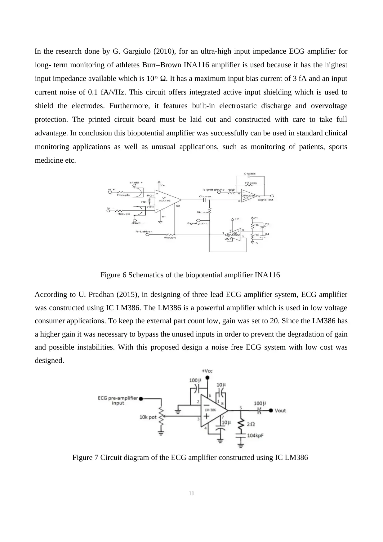
In the research done by G. Gargiulo (2010), for an ultra-high input impedance ECG amplifier for
long- term monitoring of athletes Burr–Brown INA116 amplifier is used because it has the highest
input impedance available which is 1015 Ω. It has a maximum input bias current of 3 fA and an input
current noise of 0.1 fA/√Hz. This circuit offers integrated active input shielding which is used to
shield the electrodes. Furthermore, it features built-in electrostatic discharge and overvoltage
protection. The printed circuit board must be laid out and constructed with care to take full
advantage. In conclusion this biopotential amplifier was successfully can be used in standard clinical
monitoring applications as well as unusual applications, such as monitoring of patients, sports
medicine etc.
Figure 6 Schematics of the biopotential amplifier INA116
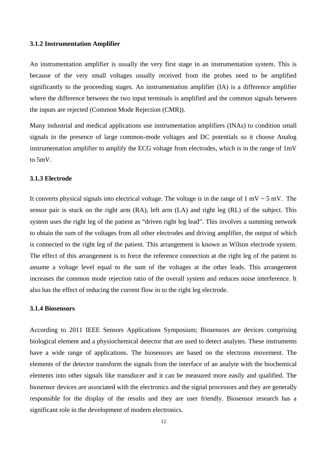
According to U. Pradhan (2015), in designing of three lead ECG amplifier system, ECG amplifier
was constructed using IC LM386. The LM386 is a powerful amplifier which is used in low voltage
consumer applications. To keep the external part count low, gain was set to 20. Since the LM386 has
a higher gain it was necessary to bypass the unused inputs in order to prevent the degradation of gain
and possible instabilities. With this proposed design a noise free ECG system with low cost was
designed.
Figure 7 Circuit diagram of the ECG amplifier constructed using IC LM386
11
long- term monitoring of athletes Burr–Brown INA116 amplifier is used because it has the highest
input impedance available which is 1015 Ω. It has a maximum input bias current of 3 fA and an input
current noise of 0.1 fA/√Hz. This circuit offers integrated active input shielding which is used to
shield the electrodes. Furthermore, it features built-in electrostatic discharge and overvoltage
protection. The printed circuit board must be laid out and constructed with care to take full
advantage. In conclusion this biopotential amplifier was successfully can be used in standard clinical
monitoring applications as well as unusual applications, such as monitoring of patients, sports
medicine etc.
Figure 6 Schematics of the biopotential amplifier INA116
According to U. Pradhan (2015), in designing of three lead ECG amplifier system, ECG amplifier
was constructed using IC LM386. The LM386 is a powerful amplifier which is used in low voltage
consumer applications. To keep the external part count low, gain was set to 20. Since the LM386 has
a higher gain it was necessary to bypass the unused inputs in order to prevent the degradation of gain
and possible instabilities. With this proposed design a noise free ECG system with low cost was
designed.
Figure 7 Circuit diagram of the ECG amplifier constructed using IC LM386
11
3.1.2 Instrumentation Amplifier
An instrumentation amplifier is usually the very first stage in an instrumentation system. This is
because of the very small voltages usually received from the probes need to be amplified
significantly to the proceeding stages. An instrumentation amplifier (IA) is a difference amplifier
where the difference between the two input terminals is amplified and the common signals between
the inputs are rejected (Common Mode Rejection (CMR)).
Many industrial and medical applications use instrumentation amplifiers (INAs) to condition small
signals in the presence of large common-mode voltages and DC potentials so it choose Analog
instrumentation amplifier to amplify the ECG voltage from electrodes, which is in the range of 1mV
to 5mV.
3.1.3 Electrode
It converts physical signals into electrical voltage. The voltage is in the range of 1 mV ~ 5 mV. The
sensor pair is stuck on the right arm (RA), left arm (LA) and right leg (RL) of the subject. This
system uses the right leg of the patient as “driven right leg lead”. This involves a summing network
to obtain the sum of the voltages from all other electrodes and driving amplifier, the output of which
is connected to the right leg of the patient. This arrangement is known as Wilson electrode system.
The effect of this arrangement is to force the reference connection at the right leg of the patient to
assume a voltage level equal to the sum of the voltages at the other leads. This arrangement
increases the common mode rejection ratio of the overall system and reduces noise interference. It
also has the effect of reducing the current flow in to the right leg electrode.
3.1.4 Biosensors
According to 2011 IEEE Sensors Applications Symposium; Biosensors are devices comprising
biological element and a physiochemical detector that are used to detect analytes. These instruments
have a wide range of applications. The biosensors are based on the electrons movement. The
elements of the detector transform the signals from the interface of an analyte with the biochemical
elements into other signals like transducer and it can be measured more easily and qualified. The
biosensor devices are associated with the electronics and the signal processors and they are generally
responsible for the display of the results and they are user friendly. Biosensor research has a
significant role in the development of modern electronics.
12
⊘ This is a preview!⊘
Do you want full access?
Subscribe today to unlock all pages.
Trusted by 1+ million students worldwide
1 out of 28
Your All-in-One AI-Powered Toolkit for Academic Success.
+13062052269
info@desklib.com
Available 24*7 on WhatsApp / Email
![[object Object]](/_next/static/media/star-bottom.7253800d.svg)
Unlock your academic potential
Copyright © 2020–2026 A2Z Services. All Rights Reserved. Developed and managed by ZUCOL.