Audio Amplifier Design Report: BJT Class-AB Output Stage, 8 Ohm
VerifiedAdded on 2023/06/15
|13
|2054
|268
Report
AI Summary
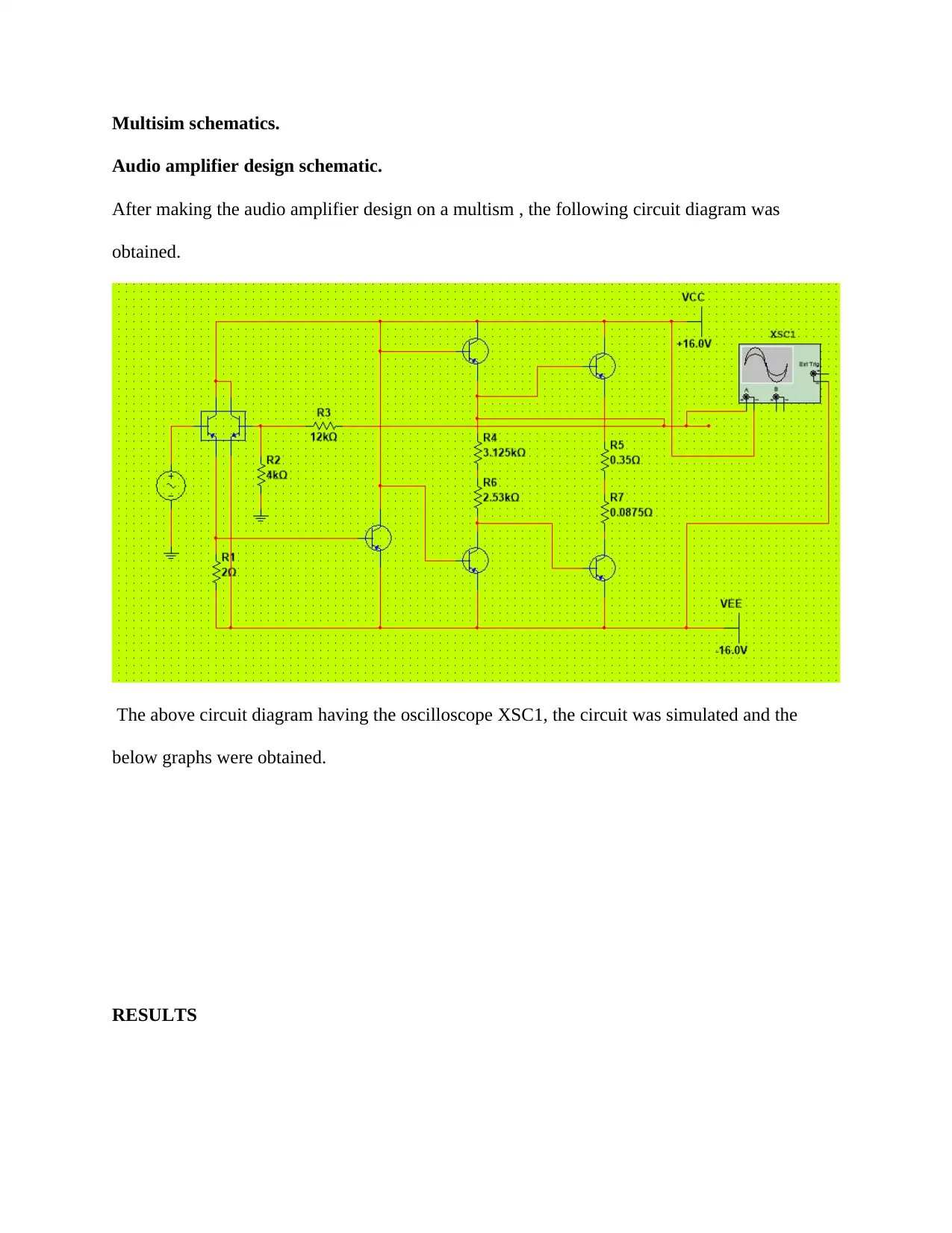
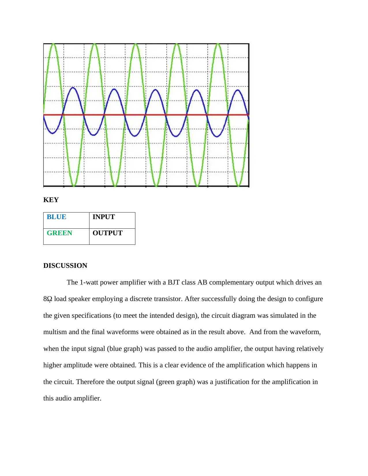
This report details the design of an audio amplifier using a bipolar transistor long-tail pair input stage and a 1W BJT class-AB complementary output stage, intended to drive an 8-ohm speaker with discrete transistors. The design adheres to specifications including a minimum voltage gain of 1500 and compliance with a +16V supply rail. The report covers the design process, component selection (BC817, BC807, BC548C), theoretical calculations for resistor values and voltage gains, DC analysis, and simulation results obtained using Multisim. The amplifier's performance is analyzed, discrepancies between simulated and calculated values are discussed, and the overall functionality and efficiency of the class AB amplifier are evaluated, highlighting its advantages in terms of efficiency, linearity, and low crossover distortion. The report concludes with a summary of the design process and results, supported by datasheets, schematics, and relevant bibliography.

DESIGNING AN AUDIO AMPLIFIER.
By Name
Course
Instructor
Institution
Location
Date
By Name
Course
Instructor
Institution
Location
Date
Paraphrase This Document
Need a fresh take? Get an instant paraphrase of this document with our AI Paraphraser

INTRODUCTION.
This is brief report discussing the steps involved in designing an audio amplifier employing a
bipolar transistor long tail pair input stage and a 1W BJT class –AB complementary output stage
to drive an 8-ohm speaker using discrete transistors. The circuit was designed to step by step in
stages on the following specified requirements.
A minimum voltage gain of 1500.
Ensure a maximum output compliance using +16V supply rail.
The audio should employ a Long Tail pair bipolar transistor at the input stage.
The audio amplifier should also employ a class AB complementary feedback-pair output
transistors.
With the above-given specifications on the design of the audio amplifier, a perfect audio
amplifier can be designed and simulated. The designed amplifier can hence be employed in
several sectors like in home theater system, public address, and mobile phones.The design
was made theoretically then tested using Multisim. Some circuit diagrams were done by hand
then snipped. The report also contains datasheets of the selected transistors, measurements
and design schematics. An audio power amplifier design has three major stage and these
stages include the following;
i. Input stage
ii. Voltage amplification stage
iii. Output Stage

For several voltage amplification purposes, a single transistor doesn’t give enough voltage gain
for a perfect functioning of the audio amplifier. Hence several circuits ( stages of the
amplification) are required. If there are several stages in amplifier the total voltage gain is the
product of individual stage gain as shown below;
Overall voltage gain AV = AV1×Av2×Av3. Basically, this amplifier is employed to raise the
strength (amplitude) of the audio signal which passes through the simplifier. In many cases, the
input signal of this audio amplifier may only measure a few hundred microwatts. These
amplifiers are usually used in the home audio system, theatrical sound reinforcement, and
concert and also in the public address system. Basically, they are used where the input signal is
relatively low and a higher voltage signal is expected at the output, this is what is referred to as
amplification. There are three major classes of amplifiers, namely class A, class B, and class
AB, but there are others like class D, class G, class DG, in this design we employed the use of
class AB amplifier.
DEVICE DATASHEET
BC817
Symbols Parameter values unit
VcB0 Collector- Base voltage 50 V
VcE0 Collector- emitter -voltage 45 V
VEB0 Emitter- Base voltage 5 V
Ic Collector Current 800 mA
BC807
Symbols Parameter values unit
⊘ This is a preview!⊘
Do you want full access?
Subscribe today to unlock all pages.

Trusted by 1+ million students worldwide

VcB0 Collector- Base voltage -50 V
VcE0 Collector- emitter -voltage -45 V
VEB0 Emitter- Base voltage -5 V
Ic Collector Current -800 mA
Reasons for class AB complementary transistors.
They are easier to stabilize because they have only one controlling Vbe.
They have a relatively high efficiency of 78%.
They are not affected by crossover distortion.
They are suitable for audio frequency driver and low power output stages.
They are complementary to each other. For example BC817 and BC807.
BC548C (NPN)
Symbols Parameter values unit
VcB0 Collector- Base voltage 30 V
VcE0 Collector- emitter -voltage 30 V
VEB0 Emitter- Base voltage 5 V
Ic Collector Current 100 mA
Wtotal Total power dissipation 0.5 W
Cc Collector capacitance 4.5 pF
Ft Transmission Frequency 200 MHz
Paraphrase This Document
Need a fresh take? Get an instant paraphrase of this document with our AI Paraphraser

Audio amplifier design schematic.
After making the audio amplifier design on a mutism , the following circuit diagram was
obtained.
Amplifier Design Analysis.
Differential input stage {Long-Tail pair (BC548C)}.
The three transistors Q1 and Q2 in the input differential pair form an arrangement known as the
Long-Tail Pair (LTP) because it’s supplied with a tail current from a very high impedance
circuit. This type of input normally has a small voltage gain, which varies from 1 to 15. The
fraction of the output to which the input is compared is determined by the voltage divider
consisting of R3 and R2.
The forward path gain of the amplifier without a negative feedback is the open loop gain (Aol).
With a large open loop gain is large, the error signal across the transistors Q1 and Q2 must be
very small to generate the desired output (Berkhout, 2003).
Voltage Amplifier Stage.

Transistors known as Q3 from the diagram is the core of this stage. It has a very high gain at the
common emitter stage that produces the bulk of the voltage gain in the amplifier. This stage
comprises of the following
i. Driver transistor
ii. A bias spreader
As shown below
Output stage.
This comprises of the transistors Q4-Q7.
The design also consists of a bias spreader implemented with Q5 connected as a Vbe multiplier
(Van der Zee, 2009).
Calculation.
The voltage gain is given as 1500,
Then the voltage at the output and input required can be obtained as below;
AV = Vout
Vin = 1500
The output power is given as 1 kW, and the resistance at the output speaker is 8ῼ
Hence the voltage at the output is
P= V 2
R
⊘ This is a preview!⊘
Do you want full access?
Subscribe today to unlock all pages.

Trusted by 1+ million students worldwide

V2 =PR
V2= PR
V=√8 = 2.828 V
Vout= 2.828
2.828
Vin =1500
Vin = 2.828
1500
Vin= 0.0018856
Vin=1.886 mV
The voltage gain can as well help in the calculation of Rf (R2|| R3) using the below equation;
AV = Rf
R 1 = 1500
SO the value of R1 can be taken as arbitrary value say 2ῼ
Rf= 1500 R1
Rf= 1500×2
Rf= 3000ῼ or 3kῼ
The value of R2 and R3 can be obtained as follows;
Taking the arbitrary value of R2 to be 4kῼ then the value of R3 in the voltage regulator is
obtained
R 2 × R 3
R 2+ R 3 =3
4R3= 3(4+R3)
4R3=12+3R3
R3= 12
Paraphrase This Document
Need a fresh take? Get an instant paraphrase of this document with our AI Paraphraser

The value of R4 and R6 can be obtained from the datasheet BC 817,
R4
Collector- base voltage =50 V
Collector current = 0.8 A
R4 = V 2
P = 502
0.8 = 3.125 kῼ
R4 = 3.125
R5
Collector- base voltage =50 V
Collector current = 0.8 A
R4 = V 2
P = 452
0.8 = 2.53 kῼ
R4 = 3.125
From the design specification
8ῼ is employed at the output speaker load. VCC of +16 volts is employed and VEE of -16 volts
is used.
Therefore Iout can be calculated as below
Iout = VCC
RL = 16
8 = 2A
Current at the Bias speaker is obtained as below
Ibias= 4 Iout
Ibias = 8A
Therefore the value of R5 will be given by
R5 = 0.7
2 = 0.35 ῼ

R7 is obtained as shown below
R7 = 0.7
8 = 0.0875ῼ
The value of 0.7 used is the breakthrough voltage silicon semiconductor transistor Q4 and Q5.
DC ANALYSIS
VB= (VD3+ VD2) + ( -VEE)
VB = 0.7 + 0.7 + −16
VB= -14.6
VE=VB-VBE
VE= -14.6-0.7
VE= -15.3 V
VRE= VE-(-VEE)
VRE= -15.3+ 16
VRE= 0.7
IC= VRE
ℜ = 0.8 (value obtained from datasheet)
0.8 = 0.7
ℜ
RE= 0.875 ῼ
The voltage at input alone can be obtained by the following equation
AV= R 3
R1 = 12000
2 = 6000
The overall Voltage gain is hence given by the below equation
Overall gain = Input gain× amplification gain ×output gain
Av= 6000×1500×1
Av= 9 000 000
⊘ This is a preview!⊘
Do you want full access?
Subscribe today to unlock all pages.

Trusted by 1+ million students worldwide

Multisim schematics.
Audio amplifier design schematic.
After making the audio amplifier design on a multism , the following circuit diagram was
obtained.
The above circuit diagram having the oscilloscope XSC1, the circuit was simulated and the
below graphs were obtained.
RESULTS
Audio amplifier design schematic.
After making the audio amplifier design on a multism , the following circuit diagram was
obtained.
The above circuit diagram having the oscilloscope XSC1, the circuit was simulated and the
below graphs were obtained.
RESULTS
Paraphrase This Document
Need a fresh take? Get an instant paraphrase of this document with our AI Paraphraser

KEY
BLUE INPUT
GREEN OUTPUT
DISCUSSION
The 1-watt power amplifier with a BJT class AB complementary output which drives an
8ῼ load speaker employing a discrete transistor. After successfully doing the design to configure
the given specifications (to meet the intended design), the circuit diagram was simulated in the
multism and the final waveforms were obtained as in the result above. And from the waveform,
when the input signal (blue graph) was passed to the audio amplifier, the output having relatively
higher amplitude were obtained. This is a clear evidence of the amplification which happens in
the circuit. Therefore the output signal (green graph) was a justification for the amplification in
this audio amplifier.

The amplification should not change the frequency of the supplied signal, what should
change is only the amplification in most scenario. And the change in the amplitude is what is
known as the amplification which for this design is 9 000 000. This amplification is very
important since it will help to achieve a relatively higher signal with a relatively low input signal.
Therefore, in most cases, it has a very higher input amplification, very high input resistance, very
higher bandwidth, very low output resistance. After simulation, the graph obtained is the same as
the expected theoretical graphs and the calculated values also configure to the output waveform,
therefore, there is a very little discrepancy between the value simulated and the calculated ones.
CONCLUSION
After doing the design of this audio amplifier, it was higher possible to simulate this
circuit diagram successfully through the multism and the successfully obtained the waveforms
for the audio amplifier. For class AB amplifier like this, it uses two complementary transistors
for switching. This happens by each transistor on opposite half-cycle of the input signal then
getting combined at the load. These amplifiers biasing ensures that the output current flows for
more than a half cycle but less than the full cycle. The conduction angle is also raised above 180
degrees but much less than 360 degrees. The output waveform at the zero crossover period is
significantly smoothened. These decreases crossover distortion. Similarly, its notable due to the
small quiescent current that its configuration is more efficient than that of class AB. In summary,
class AB complementary is preferred at the output of an audio amplifier because of the
significantly good efficiency, high linearity and low crossover distortion leading to an output of a
very high quality
Bibliography
⊘ This is a preview!⊘
Do you want full access?
Subscribe today to unlock all pages.

Trusted by 1+ million students worldwide
1 out of 13
Related Documents

Your All-in-One AI-Powered Toolkit for Academic Success.
+13062052269
info@desklib.com
Available 24*7 on WhatsApp / Email
Unlock your academic potential
Copyright © 2020–2025 A2Z Services. All Rights Reserved. Developed and managed by ZUCOL.