Design Project: ENGT 5253 Advanced Materials Blanking Die Set Design
VerifiedAdded on 2023/04/10
|35
|3206
|291
Project
AI Summary
This document presents a design project focused on creating a blanking die set for stainless steel using CAD software. The project involves constructing 3D models of the die components (specifically for the letters 'S' and 'U'), drafting engineering drawings, selecting appropriate materials using Granta CES software, and performing stress analysis using Autodesk Inventor. The analysis includes material selection based on fatigue strength and fracture toughness, FEA to determine stress distribution under load, and a cost analysis using SolidWorks Costing tool. The results indicate the selected material (mild steel) is suitable for the applied force, with a safety factor of 15. This report details the design process, material properties, stress analysis outcomes, and cost considerations for the blanking die set.
ENGT 5253
ADVANCED MATERIALS AND DESIGN
ASSIGNMENT: DESIGN PROJECT (30%)
ADVANCED MATERIALS AND DESIGN
ASSIGNMENT: DESIGN PROJECT (30%)
Paraphrase This Document
Need a fresh take? Get an instant paraphrase of this document with our AI Paraphraser
1 BACKGROUND INFORMATION
Blanking is a cold forming process. It is a shearing process in which a die and a punch
are used to modify a thin and flexible material such as paper textile, plastic film1. The
punched-out piece is called a blank. The characteristics of a blanking process include:
a) Ability to produce economical metals
b) There is removal of workpiece material as the punch enters the die.
c) Ability to produce holes
Soft materials such as aluminum, brass, bronze, mild steel, stainless steel. Aluminum is
the most blanked material.
However, the blanking has some disadvantages such as
a) Residual cracks are generated along the cracked edges.
b) There is hardening of the workpiece along the blanked edges.
c) There is excess burr and roll-over when clearance is excess.
d) Only soft materials can be blanked.
2 PROBLEM STATEMENT
We are supposed to use a Computer Aided Design (CAD) software to design a blanking
die set to blank two letters of your name from stainless Steel sheet. A 3-D model was
supposed to be constructed on a CAD software. Engineering drawings were also
supposed to be drafted with the CAD software. Appropriate materials were supposed to
be selected. Then surface treatments were to be specified to enhance the performance of
the die set. A stress analysis (FEA) was supposed to be done on the model assemblies2.
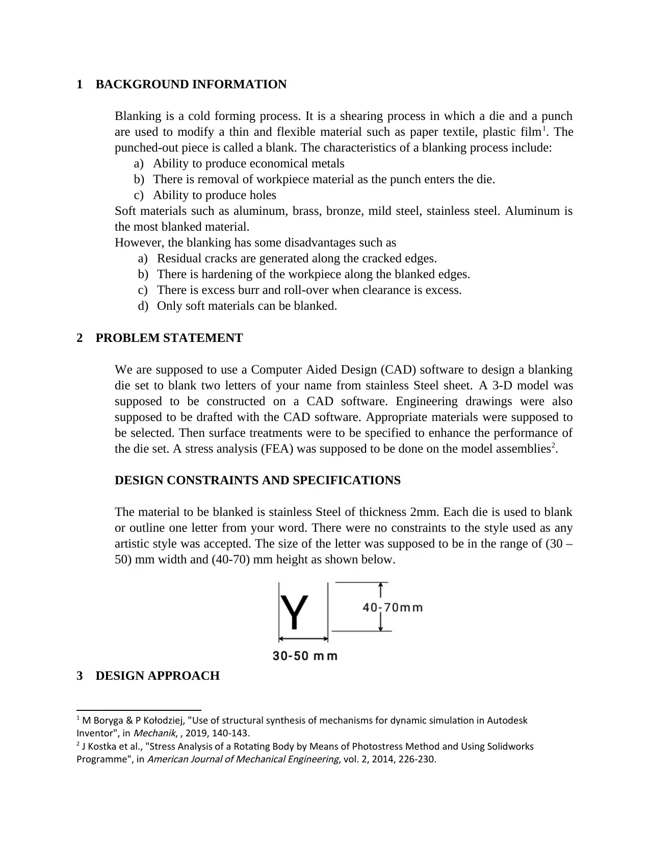
DESIGN CONSTRAINTS AND SPECIFICATIONS
The material to be blanked is stainless Steel of thickness 2mm. Each die is used to blank
or outline one letter from your word. There were no constraints to the style used as any
artistic style was accepted. The size of the letter was supposed to be in the range of (30 –
50) mm width and (40-70) mm height as shown below.
3 DESIGN APPROACH
1 M Boryga & P Kołodziej, "Use of structural synthesis of mechanisms for dynamic simulation in Autodesk
Inventor", in
Mechanik, , 2019, 140-143.
2 J Kostka et al., "Stress Analysis of a Rotating Body by Means of Photostress Method and Using Solidworks
Programme", in
American Journal of Mechanical Engineering, vol. 2, 2014, 226-230.
Blanking is a cold forming process. It is a shearing process in which a die and a punch
are used to modify a thin and flexible material such as paper textile, plastic film1. The
punched-out piece is called a blank. The characteristics of a blanking process include:
a) Ability to produce economical metals
b) There is removal of workpiece material as the punch enters the die.
c) Ability to produce holes
Soft materials such as aluminum, brass, bronze, mild steel, stainless steel. Aluminum is
the most blanked material.
However, the blanking has some disadvantages such as
a) Residual cracks are generated along the cracked edges.
b) There is hardening of the workpiece along the blanked edges.
c) There is excess burr and roll-over when clearance is excess.
d) Only soft materials can be blanked.
2 PROBLEM STATEMENT
We are supposed to use a Computer Aided Design (CAD) software to design a blanking
die set to blank two letters of your name from stainless Steel sheet. A 3-D model was
supposed to be constructed on a CAD software. Engineering drawings were also
supposed to be drafted with the CAD software. Appropriate materials were supposed to
be selected. Then surface treatments were to be specified to enhance the performance of
the die set. A stress analysis (FEA) was supposed to be done on the model assemblies2.
DESIGN CONSTRAINTS AND SPECIFICATIONS
The material to be blanked is stainless Steel of thickness 2mm. Each die is used to blank
or outline one letter from your word. There were no constraints to the style used as any
artistic style was accepted. The size of the letter was supposed to be in the range of (30 –
50) mm width and (40-70) mm height as shown below.
3 DESIGN APPROACH
1 M Boryga & P Kołodziej, "Use of structural synthesis of mechanisms for dynamic simulation in Autodesk
Inventor", in
Mechanik, , 2019, 140-143.
2 J Kostka et al., "Stress Analysis of a Rotating Body by Means of Photostress Method and Using Solidworks
Programme", in
American Journal of Mechanical Engineering, vol. 2, 2014, 226-230.
Two letters from my name S and U were chosen as for the dies. Having known which
letters to use, 3-D models were constructed on Solidworks CAD software. The
appropriate materials3 were then selected on granta CES software after which drafting of
Engineering drawings was done on Solidworks software. A Finite Element Analysis
(FEA) was done to determine the stresses4.
4 DESIGN PROCESS
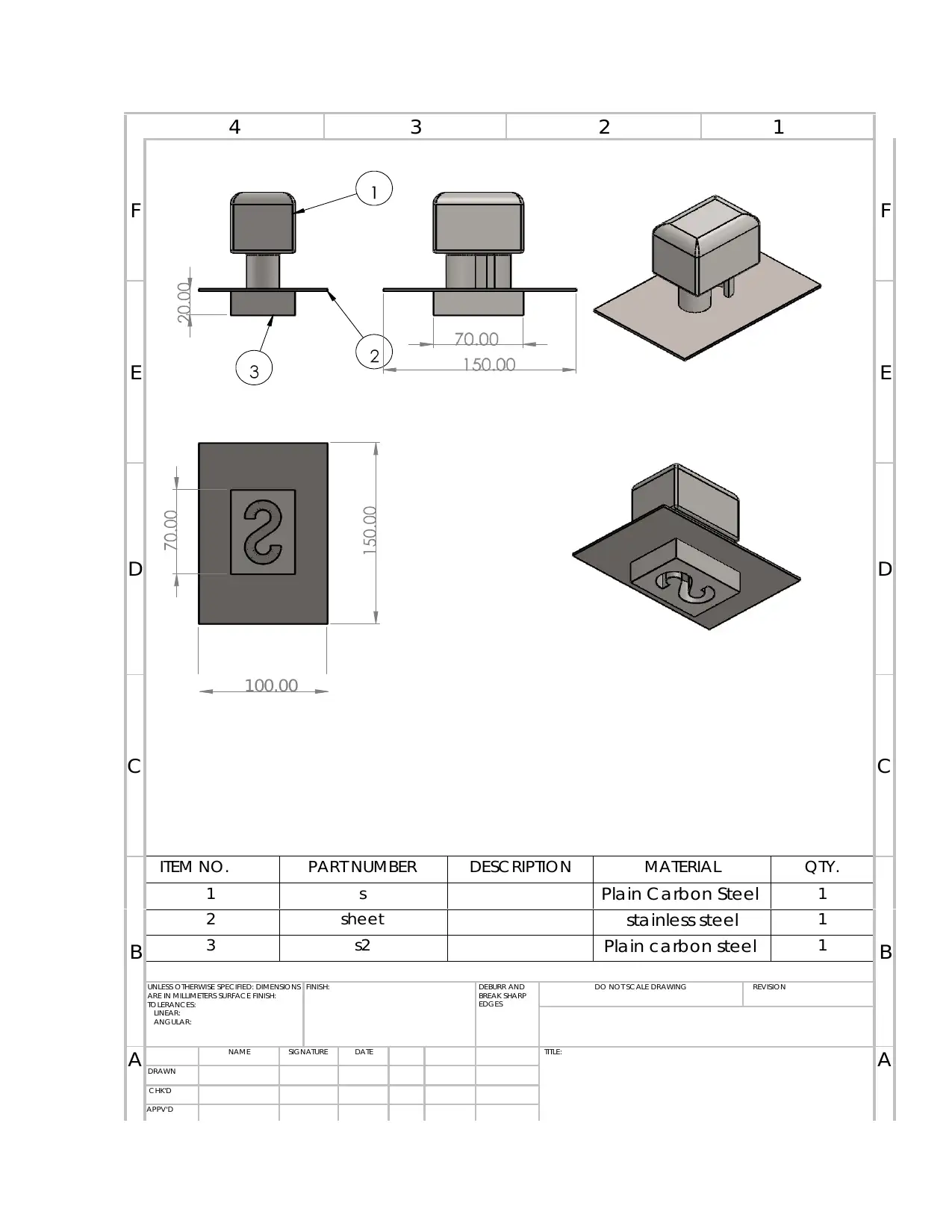
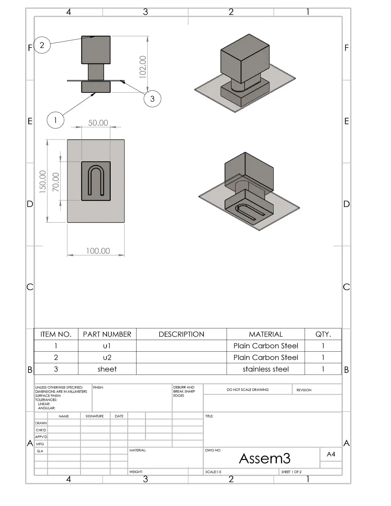
4.1 3-D MODELS
Having known the letters (S and U) the dies were modelled on Solidworks. A sheet of
dimensions 100 mm x 60 mm was also designed to help in the visualization of the die set.
(DUE TO THE FILE TYPE, THE CAD 3-D MODELS FILES WERE NOT INCLUDED
HERE BUT WERE PROVIDED IN ANOTHER FOLDER).
4.2 ENGINEERING DRAWINGS
Drafting of Engineering drawings was done on Solidworks. Drawings of S-assembly and
U-assembly were made.
These engineering drawings are provided next page.
3 J Kostka et al., "Stress Analysis of a Rotating Body by Means of Photostress Method and Using Solidworks
Programme", in
American Journal of Mechanical Engineering, vol. 2, 2014, 226-230.
4 schulergroup.com, "Screw presses with direct drives", in
Schulergroup.com, , 2019,
<https://www.schulergroup.com/major/download_center/broschueren_forging/download_forging/
forging_broschuere_spindelpressen_direktantrieb_e.pdf> [accessed 20 March 2019].
letters to use, 3-D models were constructed on Solidworks CAD software. The
appropriate materials3 were then selected on granta CES software after which drafting of
Engineering drawings was done on Solidworks software. A Finite Element Analysis
(FEA) was done to determine the stresses4.
4 DESIGN PROCESS
4.1 3-D MODELS
Having known the letters (S and U) the dies were modelled on Solidworks. A sheet of
dimensions 100 mm x 60 mm was also designed to help in the visualization of the die set.
(DUE TO THE FILE TYPE, THE CAD 3-D MODELS FILES WERE NOT INCLUDED
HERE BUT WERE PROVIDED IN ANOTHER FOLDER).
4.2 ENGINEERING DRAWINGS
Drafting of Engineering drawings was done on Solidworks. Drawings of S-assembly and
U-assembly were made.
These engineering drawings are provided next page.
3 J Kostka et al., "Stress Analysis of a Rotating Body by Means of Photostress Method and Using Solidworks
Programme", in
American Journal of Mechanical Engineering, vol. 2, 2014, 226-230.
4 schulergroup.com, "Screw presses with direct drives", in
Schulergroup.com, , 2019,
<https://www.schulergroup.com/major/download_center/broschueren_forging/download_forging/
forging_broschuere_spindelpressen_direktantrieb_e.pdf> [accessed 20 March 2019].
⊘ This is a preview!⊘
Do you want full access?
Subscribe today to unlock all pages.
Trusted by 1+ million students worldwide
4 3 2 1
F F
E E
D D
C
100.00
C
B
ITEM NO. PART NUMBER DESC RIPTION MATERIAL QTY.
B
1 s Plain C arbon Steel 1
2 sheet stainless steel 1
3 s2 Plain carbon steel 1
UNLESS OTHERWISE SPECIFIED: DIMENSIONS
ARE IN MILLIMETERS SURFAC E FINISH:
TO LERANC ES:
LINEAR:
ANGULAR:
FINISH: DEBURR AND
BREAK SHARP
EDGES
DO NOT SC ALE DRAWING REVISION
A NAME SIGNATURE DATE TITLE:
ADRAWN
C HK'D
APPV'D
Paraphrase This Document
Need a fresh take? Get an instant paraphrase of this document with our AI Paraphraser
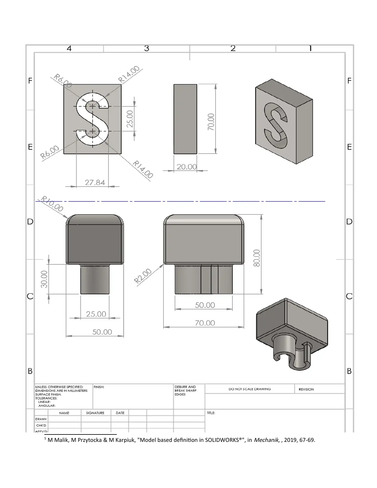
5 M Malik, M Przytocka & M Karpiuk, "Model based definition in SOLIDWORKS®", in
Mechanik, , 2019, 67-69.
Mechanik, , 2019, 67-69.
⊘ This is a preview!⊘
Do you want full access?
Subscribe today to unlock all pages.
Trusted by 1+ million students worldwide
67
6
7
6
7
Paraphrase This Document
Need a fresh take? Get an instant paraphrase of this document with our AI Paraphraser
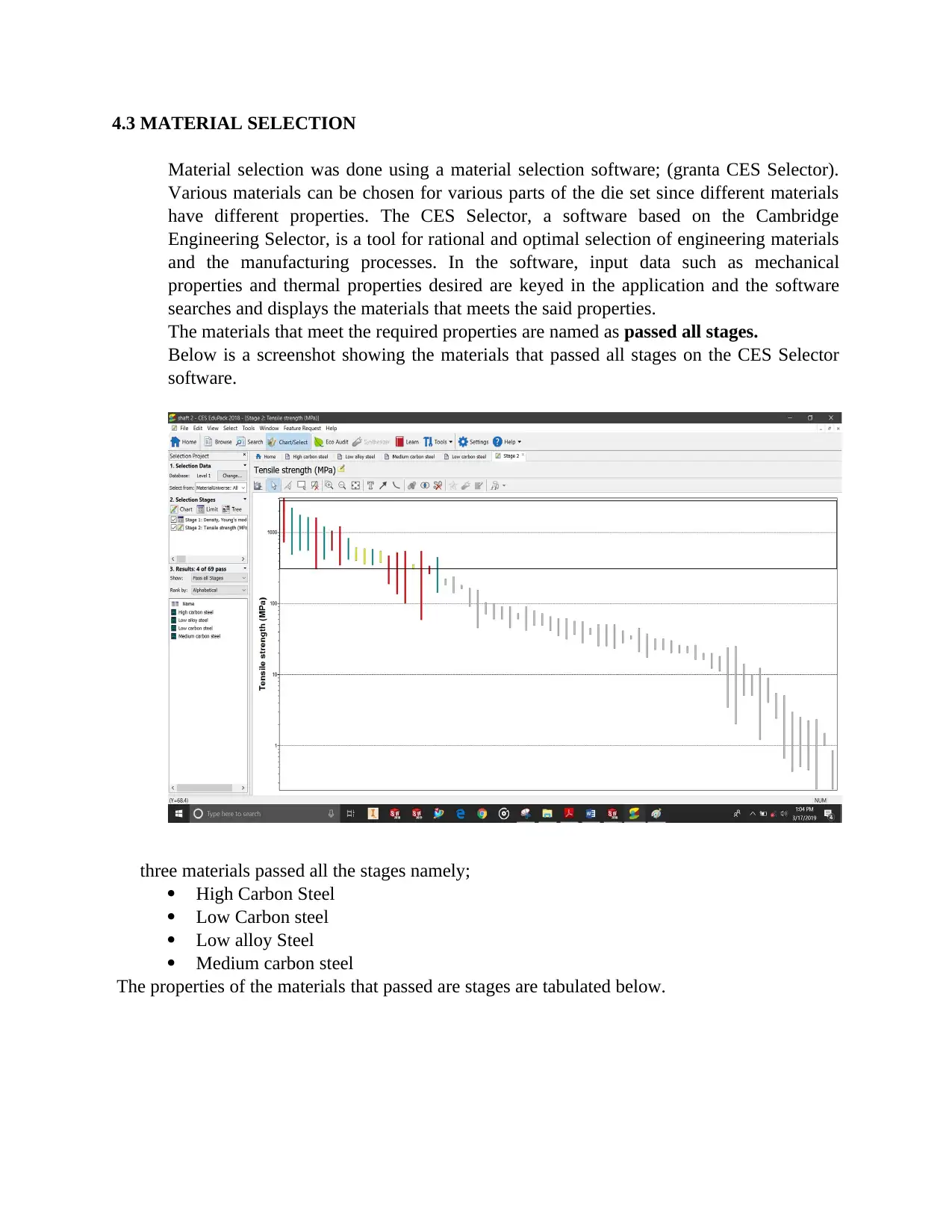
4.3 MATERIAL SELECTION
Material selection was done using a material selection software; (granta CES Selector).
Various materials can be chosen for various parts of the die set since different materials
have different properties. The CES Selector, a software based on the Cambridge
Engineering Selector, is a tool for rational and optimal selection of engineering materials
and the manufacturing processes. In the software, input data such as mechanical
properties and thermal properties desired are keyed in the application and the software
searches and displays the materials that meets the said properties.
The materials that meet the required properties are named as passed all stages.
Below is a screenshot showing the materials that passed all stages on the CES Selector
software.
three materials passed all the stages namely;
High Carbon Steel
Low Carbon steel
Low alloy Steel
Medium carbon steel
The properties of the materials that passed are stages are tabulated below.
⊘ This is a preview!⊘
Do you want full access?
Subscribe today to unlock all pages.
Trusted by 1+ million students worldwide
MATER
IAL
PROPERTY
High carbon
steel
Low alloy steel Medium carbon
steel
Low Carbon
Steel
min max min max min max max min
Density
(kg/m3)
7.8e3 7.9e3 7.8e3 7.9e3 7.8e3 7.9e3 7.8e3 7.9e3
Price
(USD/Kg)
0.65 0.7 0.7 0.76 0.65 0.71 0.65 0.7
Yield strength
(MPa)
400 1.16e3 250 395 305 900 400 1.5e3
Fracture
toughness
(MPa.m^0.5)
27 92 14 82 12 92 14 200
Fatigue strength
(MPa)
281 606 248 700 229 600 203 293
Hardness -
Vickers
(HV)
160 650 140 693 120 565 108 173
One area where a punch die can fail is due to fatigue. Stress as a result of cycles of stress
at the same point. Hence, we want a material that has a high fatigue stress. We rule out
low alloy steel even though they can be easily rolled to required shapes. Next, a material
that can be able to withstand large forces before fracturing is desired since we don’t want
our die head to fracture. Comparing the remaining three metals, low carbon steel is
chosen because it has a higher Yield Strength and Fracture toughness than both high
carbon steel and Medium carbon steel. a good example is a mild steel.
Another advantage of these metal is that case hardening will occur on the die head very
easily once you start hammering on it.
4.4 STRESS ANALYSIS (FEA)
A static stress analysis for the S and U letters assemblies was carried out on Autodesk
Inventor.
4.4.1 STRESS ANALYSYS ON S-DIE
To do the simulation. The assembly was held upright just as the way it is supposed to be
during punching operation. It was constrained at the bottom and a hammering/punching
force of 100 N was applied at the top.
Paraphrase This Document
Need a fresh take? Get an instant paraphrase of this document with our AI Paraphraser
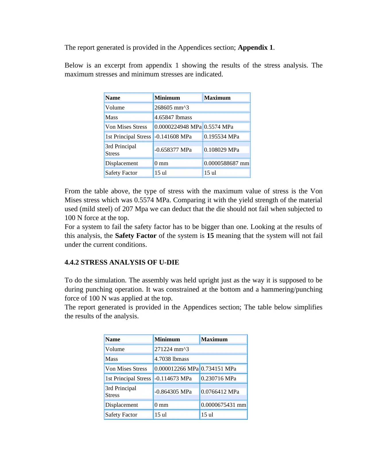
The report generated is provided in the Appendices section; Appendix 1.
Below is an excerpt from appendix 1 showing the results of the stress analysis. The
maximum stresses and minimum stresses are indicated.
Name Minimum Maximum
Volume 268605 mm^3
Mass 4.65847 lbmass
Von Mises Stress 0.0000224948 MPa 0.5574 MPa
1st Principal Stress -0.141608 MPa 0.195534 MPa
3rd Principal
Stress -0.658377 MPa 0.108029 MPa
Displacement 0 mm 0.0000588687 mm
Safety Factor 15 ul 15 ul
From the table above, the type of stress with the maximum value of stress is the Von
Mises stress which was 0.5574 MPa. Comparing it with the yield strength of the material
used (mild steel) of 207 Mpa we can deduct that the die should not fail when subjected to
100 N force at the top.
For a system to fail the safety factor has to be bigger than one. Looking at the results of
this analysis, the Safety Factor of the system is 15 meaning that the system will not fail
under the current conditions.
4.4.2 STRESS ANALYSIS OF U-DIE
To do the simulation. The assembly was held upright just as the way it is supposed to be
during punching operation. It was constrained at the bottom and a hammering/punching
force of 100 N was applied at the top.
The report generated is provided in the Appendices section; The table below simplifies
the results of the analysis.
Name Minimum Maximum
Volume 271224 mm^3
Mass 4.7038 lbmass
Von Mises Stress 0.000012266 MPa 0.734151 MPa
1st Principal Stress -0.114673 MPa 0.230716 MPa
3rd Principal
Stress -0.864305 MPa 0.0766412 MPa
Displacement 0 mm 0.0000675431 mm
Safety Factor 15 ul 15 ul
From the table above, the type of stress with the maximum value of stress is the Von
Mises stress which was 0.734151 MPa. Comparing it with the yield strength of the
material used (mild steel) of 207 Mpa we can deduct that the die should not fail when
subjected to 100 N force at the top.
The maximum displacement is 0.0000675431 which is towards the U-corner. For a
system to fail the safety factor has to be bigger than one. Looking at the results of this
analysis, the Safety Factor of the system is 15 meaning that the system will not fail
under the current conditions.
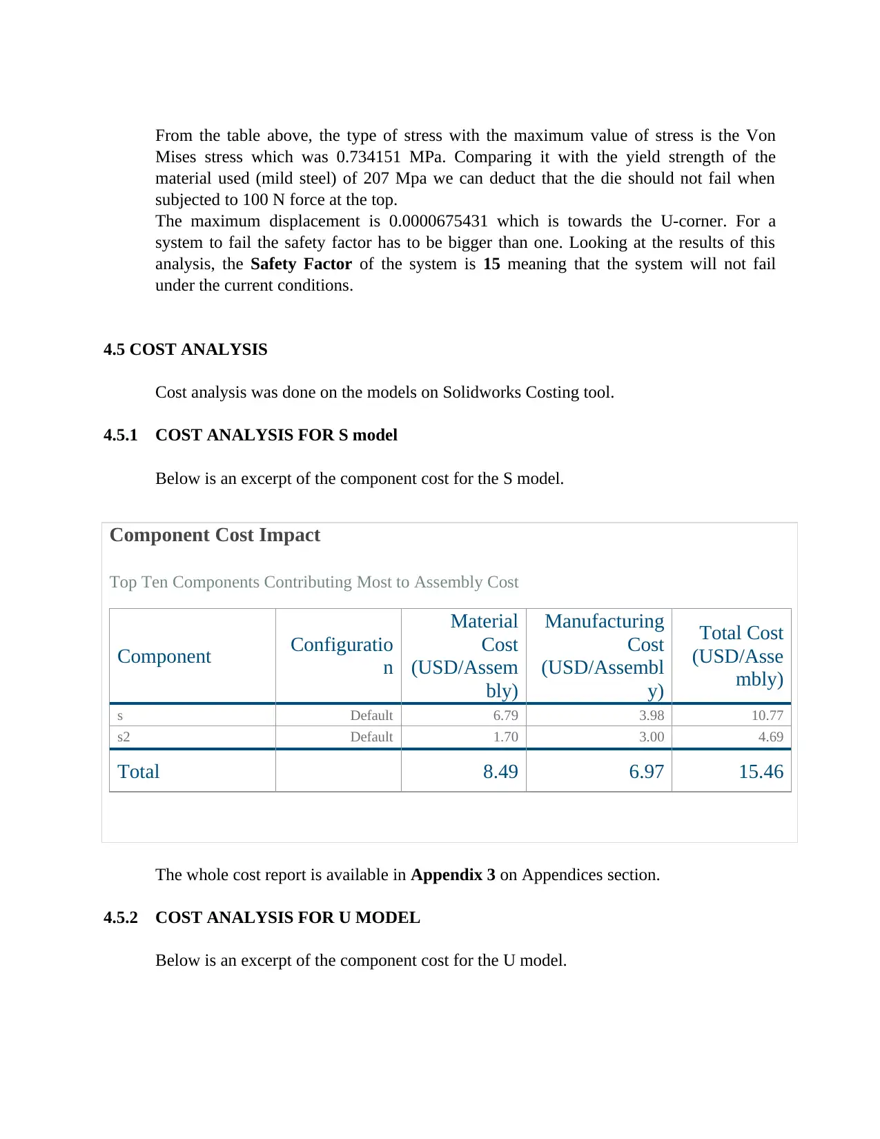
4.5 COST ANALYSIS
Cost analysis was done on the models on Solidworks Costing tool.
4.5.1 COST ANALYSIS FOR S model
Below is an excerpt of the component cost for the S model.
Component Cost Impact
Top Ten Components Contributing Most to Assembly Cost
Component Configuratio
n
Material
Cost
(USD/Assem
bly)
Manufacturing
Cost
(USD/Assembl
y)
Total Cost
(USD/Asse
mbly)
s Default 6.79 3.98 10.77
s2 Default 1.70 3.00 4.69
Total 8.49 6.97 15.46
The whole cost report is available in Appendix 3 on Appendices section.
4.5.2 COST ANALYSIS FOR U MODEL
Below is an excerpt of the component cost for the U model.
Mises stress which was 0.734151 MPa. Comparing it with the yield strength of the
material used (mild steel) of 207 Mpa we can deduct that the die should not fail when
subjected to 100 N force at the top.
The maximum displacement is 0.0000675431 which is towards the U-corner. For a
system to fail the safety factor has to be bigger than one. Looking at the results of this
analysis, the Safety Factor of the system is 15 meaning that the system will not fail
under the current conditions.
4.5 COST ANALYSIS
Cost analysis was done on the models on Solidworks Costing tool.
4.5.1 COST ANALYSIS FOR S model
Below is an excerpt of the component cost for the S model.
Component Cost Impact
Top Ten Components Contributing Most to Assembly Cost
Component Configuratio
n
Material
Cost
(USD/Assem
bly)
Manufacturing
Cost
(USD/Assembl
y)
Total Cost
(USD/Asse
mbly)
s Default 6.79 3.98 10.77
s2 Default 1.70 3.00 4.69
Total 8.49 6.97 15.46
The whole cost report is available in Appendix 3 on Appendices section.
4.5.2 COST ANALYSIS FOR U MODEL
Below is an excerpt of the component cost for the U model.
⊘ This is a preview!⊘
Do you want full access?
Subscribe today to unlock all pages.
Trusted by 1+ million students worldwide
1 out of 35

Your All-in-One AI-Powered Toolkit for Academic Success.
+13062052269
info@desklib.com
Available 24*7 on WhatsApp / Email
![[object Object]](/_next/static/media/star-bottom.7253800d.svg)
Unlock your academic potential
Copyright © 2020–2026 A2Z Services. All Rights Reserved. Developed and managed by ZUCOL.