MECH2360 Dynamics: Analysis & Report on BMW E30 'Super Eta' Engine
VerifiedAdded on 2023/03/30
|21
|3419
|376
Report
AI Summary
This report provides a comprehensive analysis of the BMW E30 'Super Eta' engine, a popular performance upgrade involving the M20 engine. The analysis covers the engine's design, focusing on its fuel efficiency and limitations in terms of power. The report delves into the kinematics and dynamics of the engine, examining parameters such as piston velocity, acceleration, and forces acting on the crank mechanism. Assumptions and limitations are clearly stated, and engineering calculations are performed to determine the impact of connecting rod length on piston and cylinder wall loading, gudgeon pin forces, and velocity-acceleration dependence. The report also considers the engine's RPM in comparison to the original 'eta' engine. Ultimately, the report provides recommendations based on the analysis, offering valuable insights for engine developers and builders looking to optimize the performance of the BMW E30 engine. Desklib offers a variety of solved assignments and past papers for students.
6/5/2019
[Document title]
[Document subtitle]
AGRIPPINA
[company name]
[Document title]
[Document subtitle]
AGRIPPINA
[company name]
Paraphrase This Document
Need a fresh take? Get an instant paraphrase of this document with our AI Paraphraser
INTRODUCTION
The BMW E30 is a modern car developed to ensure proper transport and safety while at high
speeds. The performance upgrade is based on the stroker version of the M20 with a 6-part
engine. There are many original components where the vehicle’s capacity at 2 liter to 2.7 liter.
The vehicle’s engine is built on the oil crisis period in the early years with a focus on fuel
efficiency. The vehicle provides high torque engine with efficient levels of general driving. The
vehicle needs a higher revving and large capacity engine that provides more power. The M20,
like the M10, is fairly well tuned from the factory. There is not a lot of hidden horsepower just
waiting for you to tease out. There are a few things that can be done to make the engine run
better and make a little more power, on the order of 5 to 10 percent at the wheels.
A good-running, stock M20B25 can put out up to 145 or so horse power at the rear wheels,
depending on many factors. The best thing to do is to reduce the intake restriction by replacing
the air box with a cone filter and heat shield for a small increase in airflow and power. For even
more gains you can swap out the air/fuel meter (AFM) for a larger one from a 535 or 735 with
the 3.5-liter engine. You may have to swap circuit boards from your AFM to get the idle to
smooth out.
The M20 Stroker is based on the crank centerline,
PAGE \* MERGEFORMAT 17
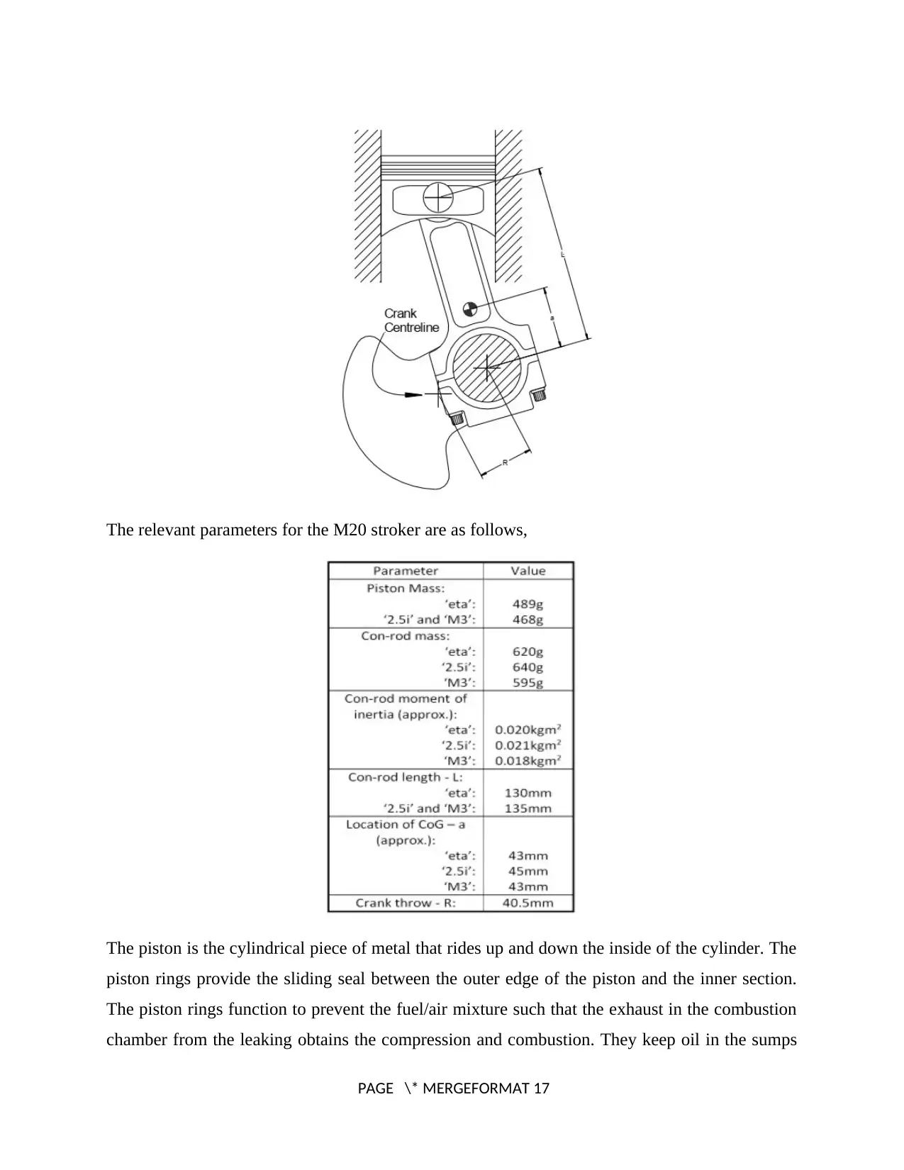
The relevant parameters for the M20 stroker are as follows,
The piston is the cylindrical piece of metal that rides up and down the inside of the cylinder. The
piston rings provide the sliding seal between the outer edge of the piston and the inner section.
The piston rings function to prevent the fuel/air mixture such that the exhaust in the combustion
chamber from the leaking obtains the compression and combustion. They keep oil in the sumps
PAGE \* MERGEFORMAT 17
⊘ This is a preview!⊘
Do you want full access?
Subscribe today to unlock all pages.
Trusted by 1+ million students worldwide
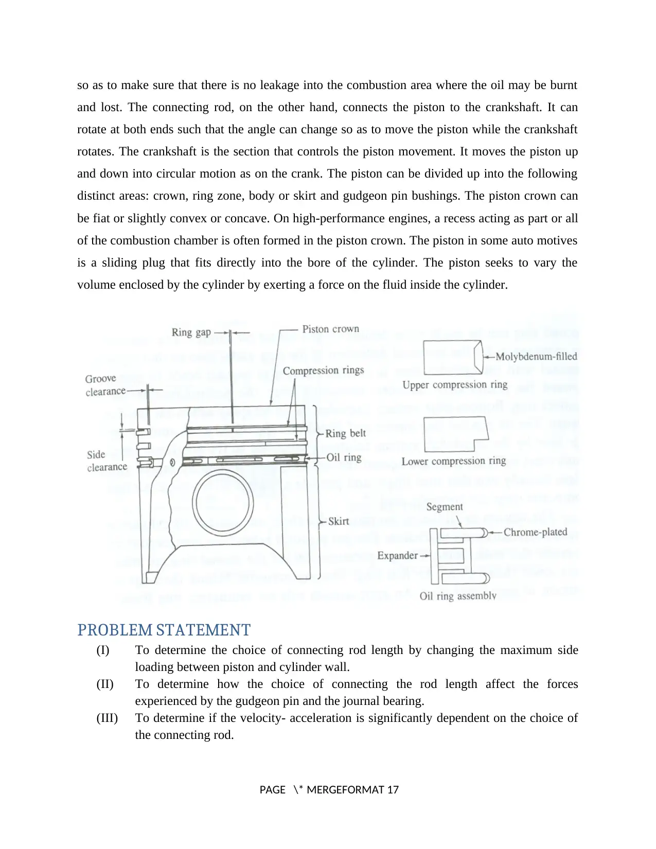
so as to make sure that there is no leakage into the combustion area where the oil may be burnt
and lost. The connecting rod, on the other hand, connects the piston to the crankshaft. It can
rotate at both ends such that the angle can change so as to move the piston while the crankshaft
rotates. The crankshaft is the section that controls the piston movement. It moves the piston up
and down into circular motion as on the crank. The piston can be divided up into the following
distinct areas: crown, ring zone, body or skirt and gudgeon pin bushings. The piston crown can
be fiat or slightly convex or concave. On high-performance engines, a recess acting as part or all
of the combustion chamber is often formed in the piston crown. The piston in some auto motives
is a sliding plug that fits directly into the bore of the cylinder. The piston seeks to vary the
volume enclosed by the cylinder by exerting a force on the fluid inside the cylinder.
PROBLEM STATEMENT
(I) To determine the choice of connecting rod length by changing the maximum side
loading between piston and cylinder wall.
(II) To determine how the choice of connecting the rod length affect the forces
experienced by the gudgeon pin and the journal bearing.
(III) To determine if the velocity- acceleration is significantly dependent on the choice of
the connecting rod.
PAGE \* MERGEFORMAT 17
Paraphrase This Document
Need a fresh take? Get an instant paraphrase of this document with our AI Paraphraser
(IV) To determine the rpm of the 2.5i and M3 as compared to the 7000 rpm of the eta
engine.
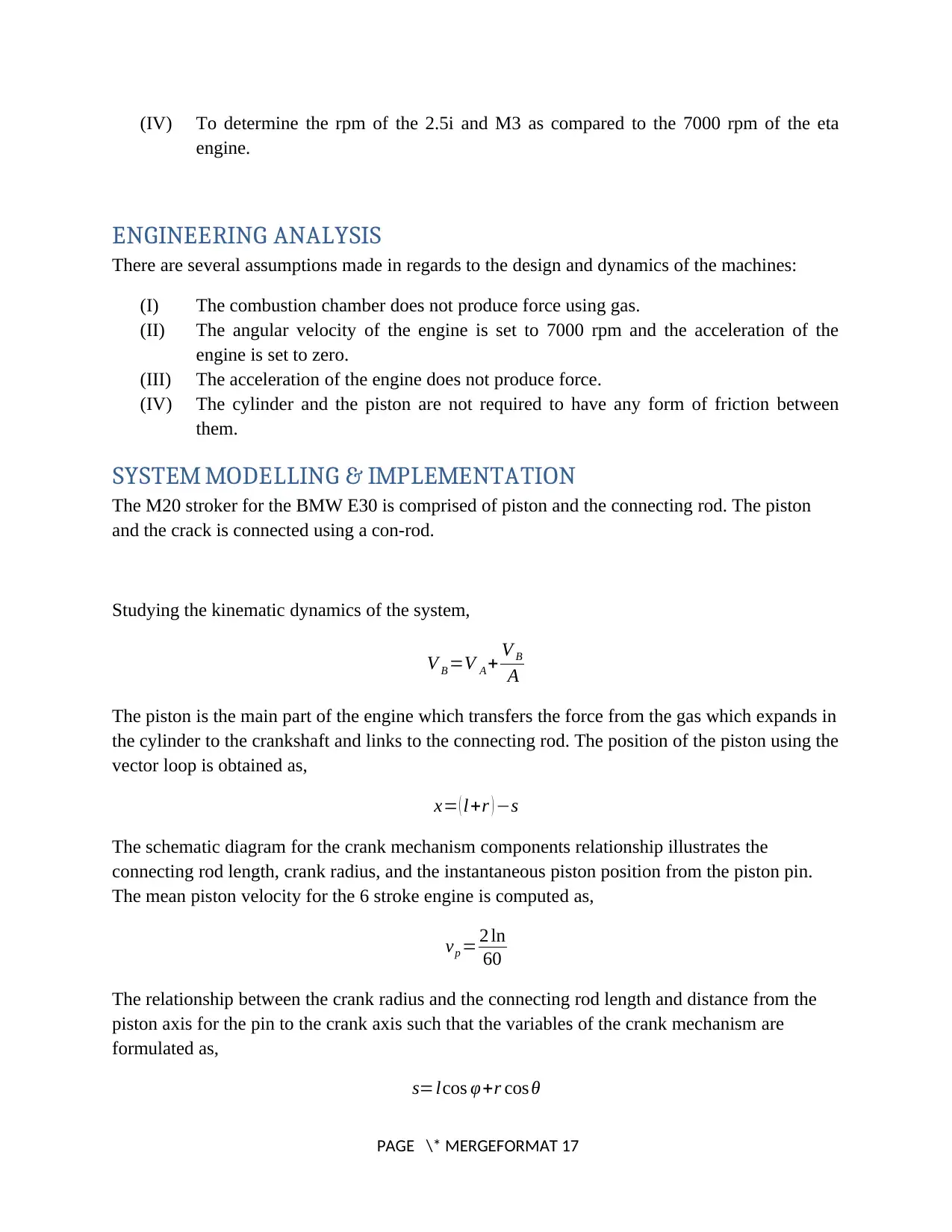
ENGINEERING ANALYSIS
There are several assumptions made in regards to the design and dynamics of the machines:
(I) The combustion chamber does not produce force using gas.
(II) The angular velocity of the engine is set to 7000 rpm and the acceleration of the
engine is set to zero.
(III) The acceleration of the engine does not produce force.
(IV) The cylinder and the piston are not required to have any form of friction between
them.
SYSTEM MODELLING & IMPLEMENTATION
The M20 stroker for the BMW E30 is comprised of piston and the connecting rod. The piston
and the crack is connected using a con-rod.
Studying the kinematic dynamics of the system,
V B =V A + V B
A
The piston is the main part of the engine which transfers the force from the gas which expands in
the cylinder to the crankshaft and links to the connecting rod. The position of the piston using the
vector loop is obtained as,
x= ( l+r ) −s
The schematic diagram for the crank mechanism components relationship illustrates the
connecting rod length, crank radius, and the instantaneous piston position from the piston pin.
The mean piston velocity for the 6 stroke engine is computed as,
vp = 2 ln
60
The relationship between the crank radius and the connecting rod length and distance from the
piston axis for the pin to the crank axis such that the variables of the crank mechanism are
formulated as,
s=lcos φ+r cos θ
PAGE \* MERGEFORMAT 17
engine.
ENGINEERING ANALYSIS
There are several assumptions made in regards to the design and dynamics of the machines:
(I) The combustion chamber does not produce force using gas.
(II) The angular velocity of the engine is set to 7000 rpm and the acceleration of the
engine is set to zero.
(III) The acceleration of the engine does not produce force.
(IV) The cylinder and the piston are not required to have any form of friction between
them.
SYSTEM MODELLING & IMPLEMENTATION
The M20 stroker for the BMW E30 is comprised of piston and the connecting rod. The piston
and the crack is connected using a con-rod.
Studying the kinematic dynamics of the system,
V B =V A + V B
A
The piston is the main part of the engine which transfers the force from the gas which expands in
the cylinder to the crankshaft and links to the connecting rod. The position of the piston using the
vector loop is obtained as,
x= ( l+r ) −s
The schematic diagram for the crank mechanism components relationship illustrates the
connecting rod length, crank radius, and the instantaneous piston position from the piston pin.
The mean piston velocity for the 6 stroke engine is computed as,
vp = 2 ln
60
The relationship between the crank radius and the connecting rod length and distance from the
piston axis for the pin to the crank axis such that the variables of the crank mechanism are
formulated as,
s=lcos φ+r cos θ
PAGE \* MERGEFORMAT 17
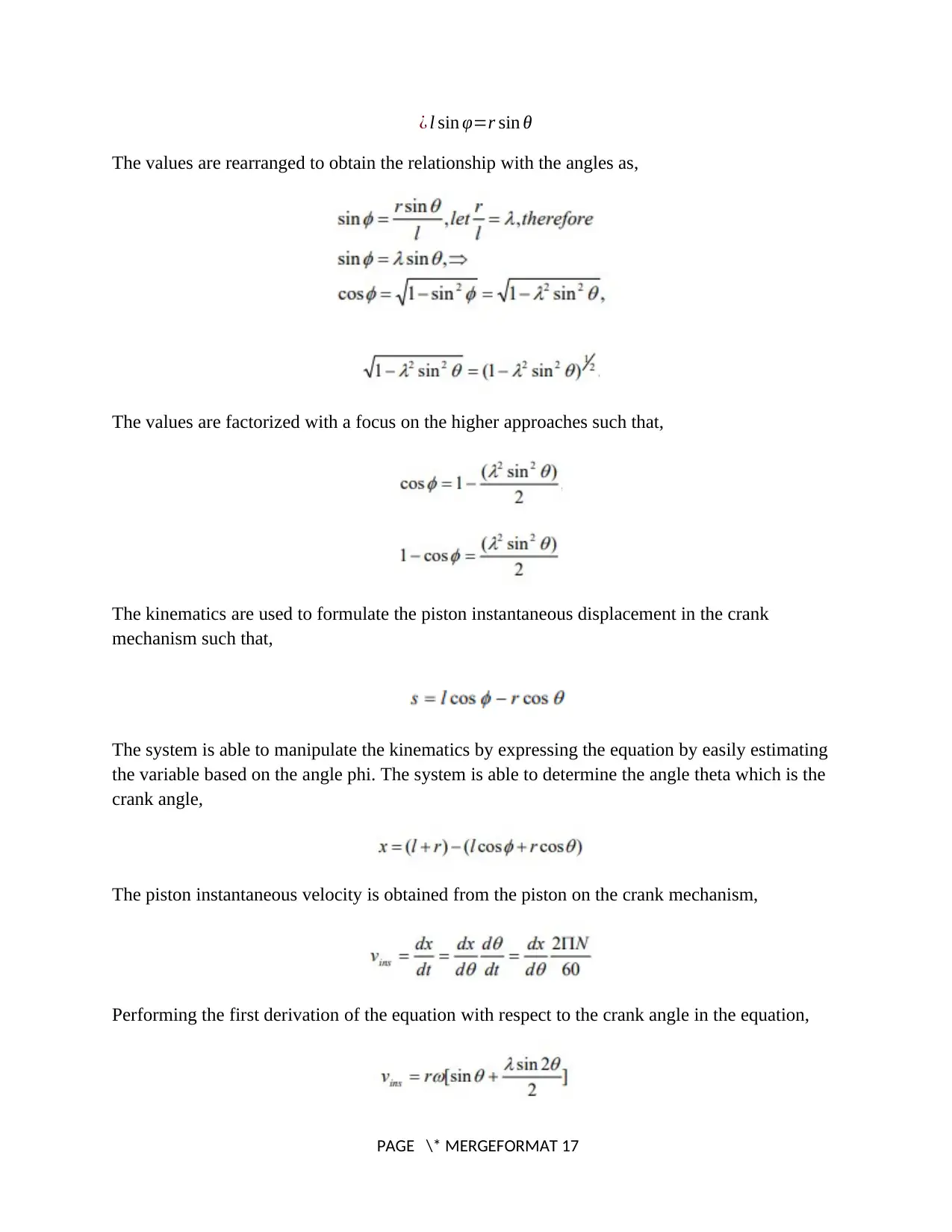
¿ l sin φ=r sin θ
The values are rearranged to obtain the relationship with the angles as,
The values are factorized with a focus on the higher approaches such that,
The kinematics are used to formulate the piston instantaneous displacement in the crank
mechanism such that,
The system is able to manipulate the kinematics by expressing the equation by easily estimating
the variable based on the angle phi. The system is able to determine the angle theta which is the
crank angle,
The piston instantaneous velocity is obtained from the piston on the crank mechanism,
Performing the first derivation of the equation with respect to the crank angle in the equation,
PAGE \* MERGEFORMAT 17
⊘ This is a preview!⊘
Do you want full access?
Subscribe today to unlock all pages.
Trusted by 1+ million students worldwide
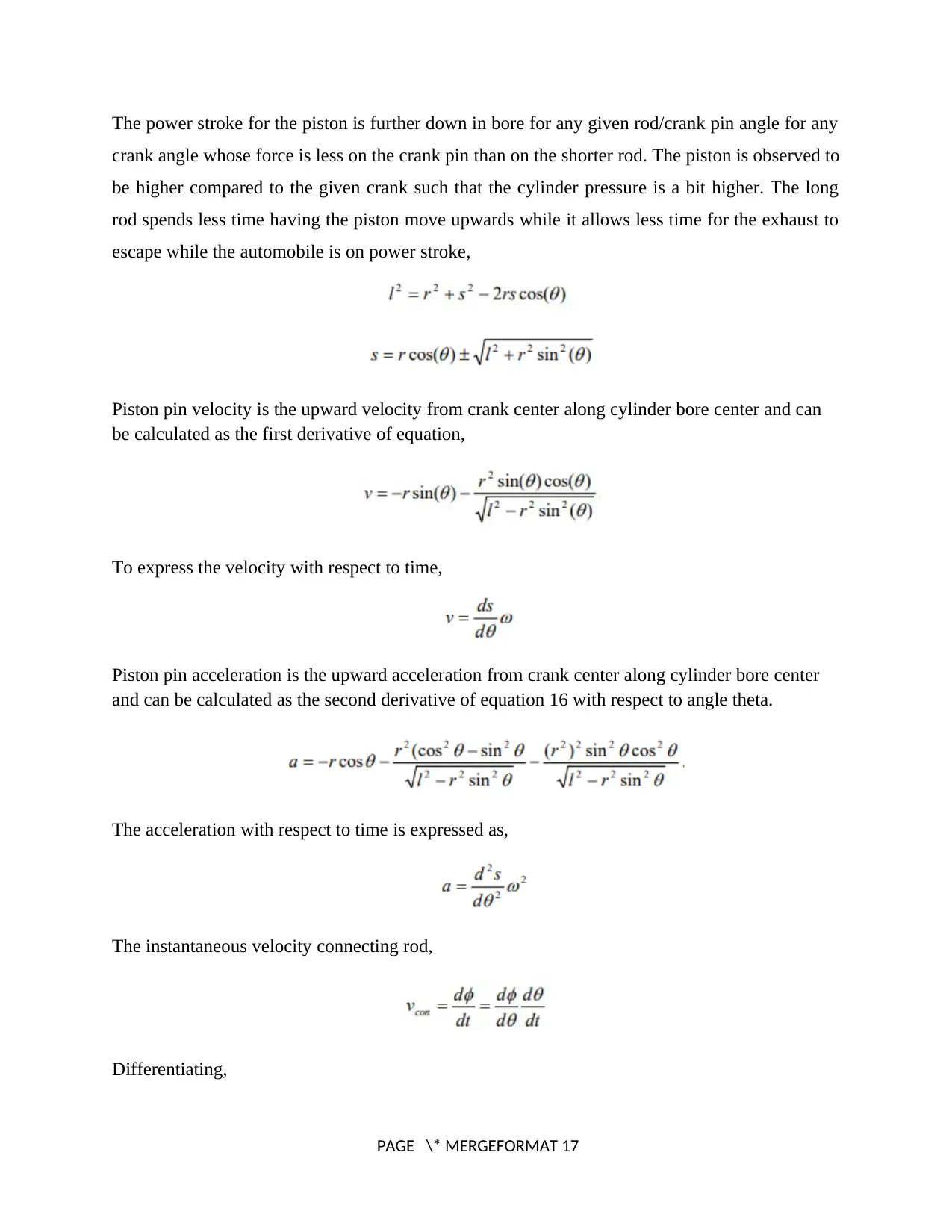
The power stroke for the piston is further down in bore for any given rod/crank pin angle for any
crank angle whose force is less on the crank pin than on the shorter rod. The piston is observed to
be higher compared to the given crank such that the cylinder pressure is a bit higher. The long
rod spends less time having the piston move upwards while it allows less time for the exhaust to
escape while the automobile is on power stroke,
Piston pin velocity is the upward velocity from crank center along cylinder bore center and can
be calculated as the first derivative of equation,
To express the velocity with respect to time,
Piston pin acceleration is the upward acceleration from crank center along cylinder bore center
and can be calculated as the second derivative of equation 16 with respect to angle theta.
The acceleration with respect to time is expressed as,
The instantaneous velocity connecting rod,
Differentiating,
PAGE \* MERGEFORMAT 17
Paraphrase This Document
Need a fresh take? Get an instant paraphrase of this document with our AI Paraphraser
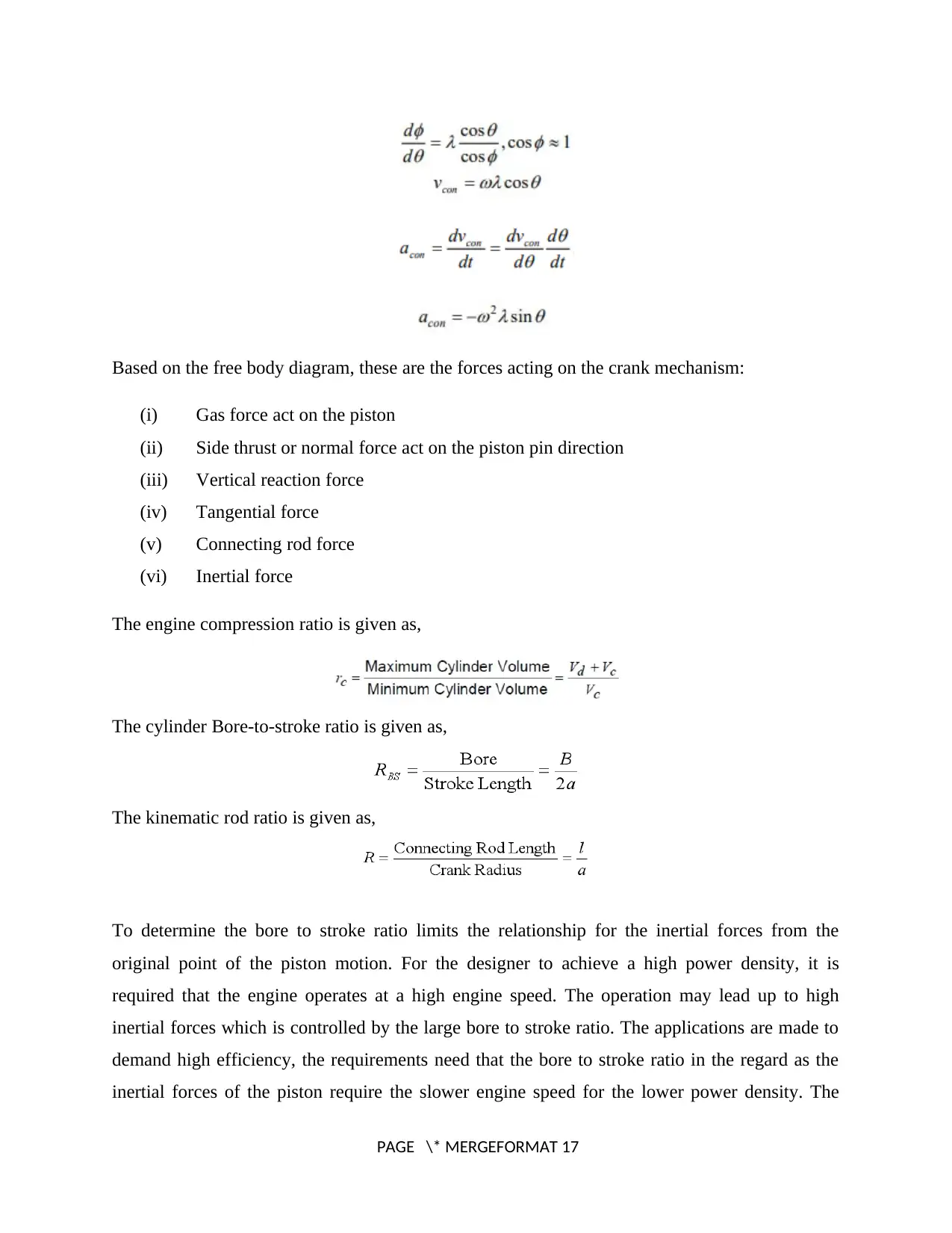
Based on the free body diagram, these are the forces acting on the crank mechanism:
(i) Gas force act on the piston
(ii) Side thrust or normal force act on the piston pin direction
(iii) Vertical reaction force
(iv) Tangential force
(v) Connecting rod force
(vi) Inertial force
The engine compression ratio is given as,
The cylinder Bore-to-stroke ratio is given as,
The kinematic rod ratio is given as,
To determine the bore to stroke ratio limits the relationship for the inertial forces from the
original point of the piston motion. For the designer to achieve a high power density, it is
required that the engine operates at a high engine speed. The operation may lead up to high
inertial forces which is controlled by the large bore to stroke ratio. The applications are made to
demand high efficiency, the requirements need that the bore to stroke ratio in the regard as the
inertial forces of the piston require the slower engine speed for the lower power density. The
PAGE \* MERGEFORMAT 17
marine application is estimated to have a 2.5 meter stroke and the engine speed is estimated to
run at a steady 102 revolutions per minute.
Most of the automobiles are being run on the internal combustion engine which may run most
automobiles in the foreseeable future. The piston speed is determined based on the position of
the crankshaft and the piston. The speed of the piston is given such that,
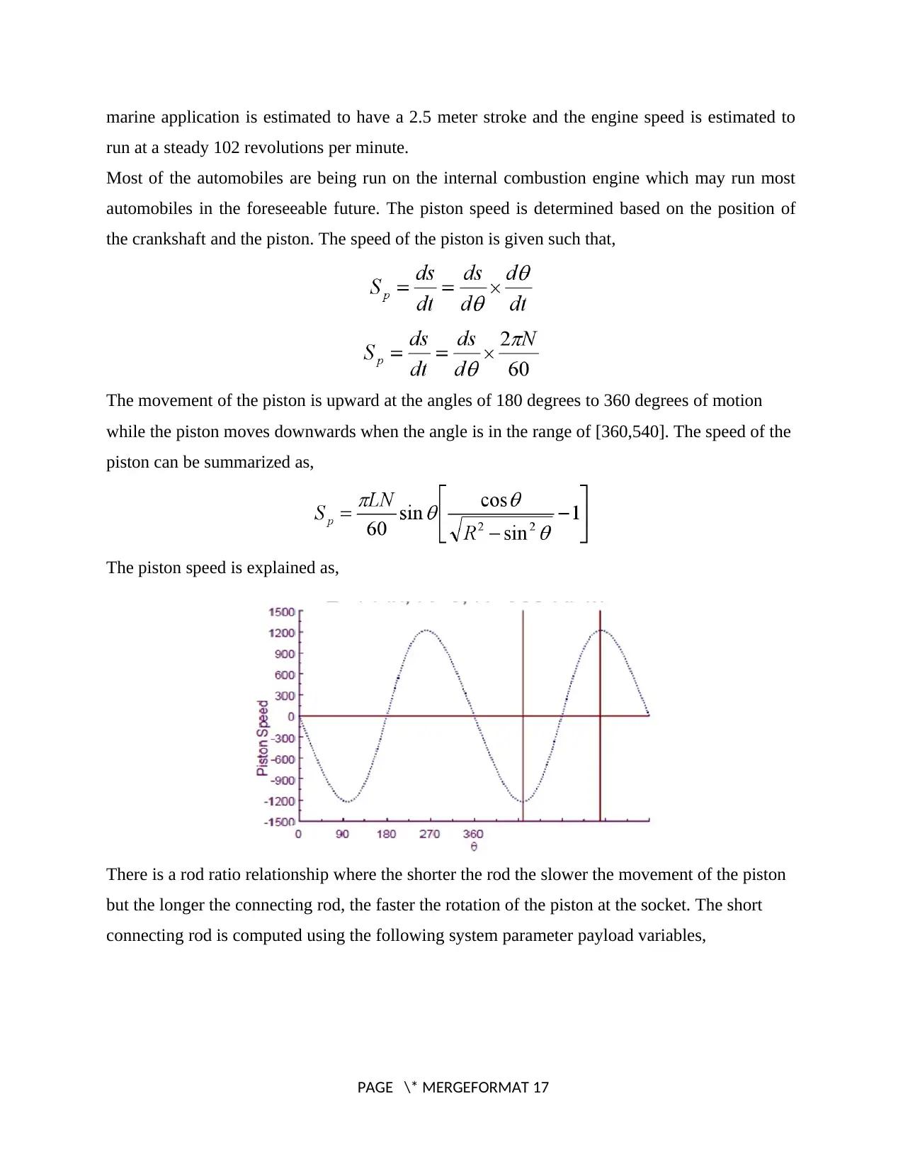
The movement of the piston is upward at the angles of 180 degrees to 360 degrees of motion
while the piston moves downwards when the angle is in the range of [360,540]. The speed of the
piston can be summarized as,
The piston speed is explained as,
There is a rod ratio relationship where the shorter the rod the slower the movement of the piston
but the longer the connecting rod, the faster the rotation of the piston at the socket. The short
connecting rod is computed using the following system parameter payload variables,
PAGE \* MERGEFORMAT 17
run at a steady 102 revolutions per minute.
Most of the automobiles are being run on the internal combustion engine which may run most
automobiles in the foreseeable future. The piston speed is determined based on the position of
the crankshaft and the piston. The speed of the piston is given such that,
The movement of the piston is upward at the angles of 180 degrees to 360 degrees of motion
while the piston moves downwards when the angle is in the range of [360,540]. The speed of the
piston can be summarized as,
The piston speed is explained as,
There is a rod ratio relationship where the shorter the rod the slower the movement of the piston
but the longer the connecting rod, the faster the rotation of the piston at the socket. The short
connecting rod is computed using the following system parameter payload variables,
PAGE \* MERGEFORMAT 17
⊘ This is a preview!⊘
Do you want full access?
Subscribe today to unlock all pages.
Trusted by 1+ million students worldwide
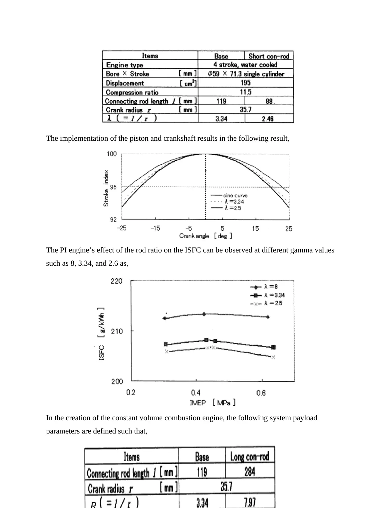
The implementation of the piston and crankshaft results in the following result,
The PI engine’s effect of the rod ratio on the ISFC can be observed at different gamma values
such as 8, 3.34, and 2.6 as,
In the creation of the constant volume combustion engine, the following system payload
parameters are defined such that,
PAGE \* MERGEFORMAT 17
The PI engine’s effect of the rod ratio on the ISFC can be observed at different gamma values
such as 8, 3.34, and 2.6 as,
In the creation of the constant volume combustion engine, the following system payload
parameters are defined such that,
PAGE \* MERGEFORMAT 17
Paraphrase This Document
Need a fresh take? Get an instant paraphrase of this document with our AI Paraphraser
The instantaneous piston displacement is given based on the piston speed for the duration of the
experiment. For a long rod, the intake stroke draws harder on the cylinder head on a
perpendicular motion while the compression stroke ensure that the piston travels over 90 degrees
to another direction a bit faster than the shorter rod. The piston is observed to move a bit slowly
compared to the movement while the ignition timing requirement are set up. The piston speed is
estimated as,
During ignition, when the connection rod is long, the flame tends to travel a longer distance in
which a detonation is bound to occur. The long rod ensures that more efficient combustion for
the internal combustion engine at very high speeds. The designer at this point may wish to
measure the carbon monoxide or the carbon dioxide value during the test. The power stroke for
the piston is further down in bore for any given rod/crank pin angle for any crank angle whose
force is less on the crank pin than on the shorter rod. The piston is observed to be higher
compared to the given crank such that the cylinder pressure is a bit higher. The long rod spends
less time having the piston move upwards while it allows less time for the exhaust to escape
while the automobile is on power stroke.
Further, it is also important to observe that the piston moves downwards in the exhaust stroke
while the cylinder pressure at this point is higher. There is a force that pushes the system to
exhaust causes more air to be pushed out of the system. The exhaust port when poor tends to
have a bad effect on the exhaust fumes and the long rod helps the peak power and ensures
increased efficiency.
The cyclic torque fluctuation leads to a variations of the crankshaft’s rotation speed, called
cyclic variation and defined as,
PAGE \* MERGEFORMAT 17
The gas torque is given as,
For the inertial torque which may result from the crankshaft and engine structure,
The forces like tangential force, connecting rod force and side thrust force can be calculated as it
depicted in that,
The connecting rod has two principal tasks to fulfil: it connects the piston to the crankshaft and,
since its lower or "big" end is attached to an offset crankpin on the crankshaft, it converts linear
movement of the piston into rotary movement of the crankshaft. By doing so, it transforms the
linear force of the piston into a rotary force or torque. The connecting rod is exposed to very
severe loads. Combustion gas pressure acting downwards on the piston exerts very heavy forces
along the connecting rod. Since the piston's speed is continually varying, the high acceleration
and deceleration forces which result must be withstood in the form of tensile and compressive
loads on the connecting rod. Furthermore, the oscillating movement of the connecting rod round
the gudgeon pin axis introduces powerful bending forces into the rod since the rod is fairly long
is also subject to buckling stresses.
RESULTS & FINDINGS
The minimum length changes are needed to observe the thermo-fluid process. To perform a
proper design for the system is intended to have about 5 percent change in the system. The
PAGE \* MERGEFORMAT 17
⊘ This is a preview!⊘
Do you want full access?
Subscribe today to unlock all pages.
Trusted by 1+ million students worldwide
1 out of 21


Your All-in-One AI-Powered Toolkit for Academic Success.
+13062052269
info@desklib.com
Available 24*7 on WhatsApp / Email
![[object Object]](/_next/static/media/star-bottom.7253800d.svg)
Unlock your academic potential
Copyright © 2020–2026 A2Z Services. All Rights Reserved. Developed and managed by ZUCOL.