Analysis and Design Report: Body Sculptures Gymnasium Facility System
VerifiedAdded on  2022/10/12
|15
|2887
|361
Report
AI Summary
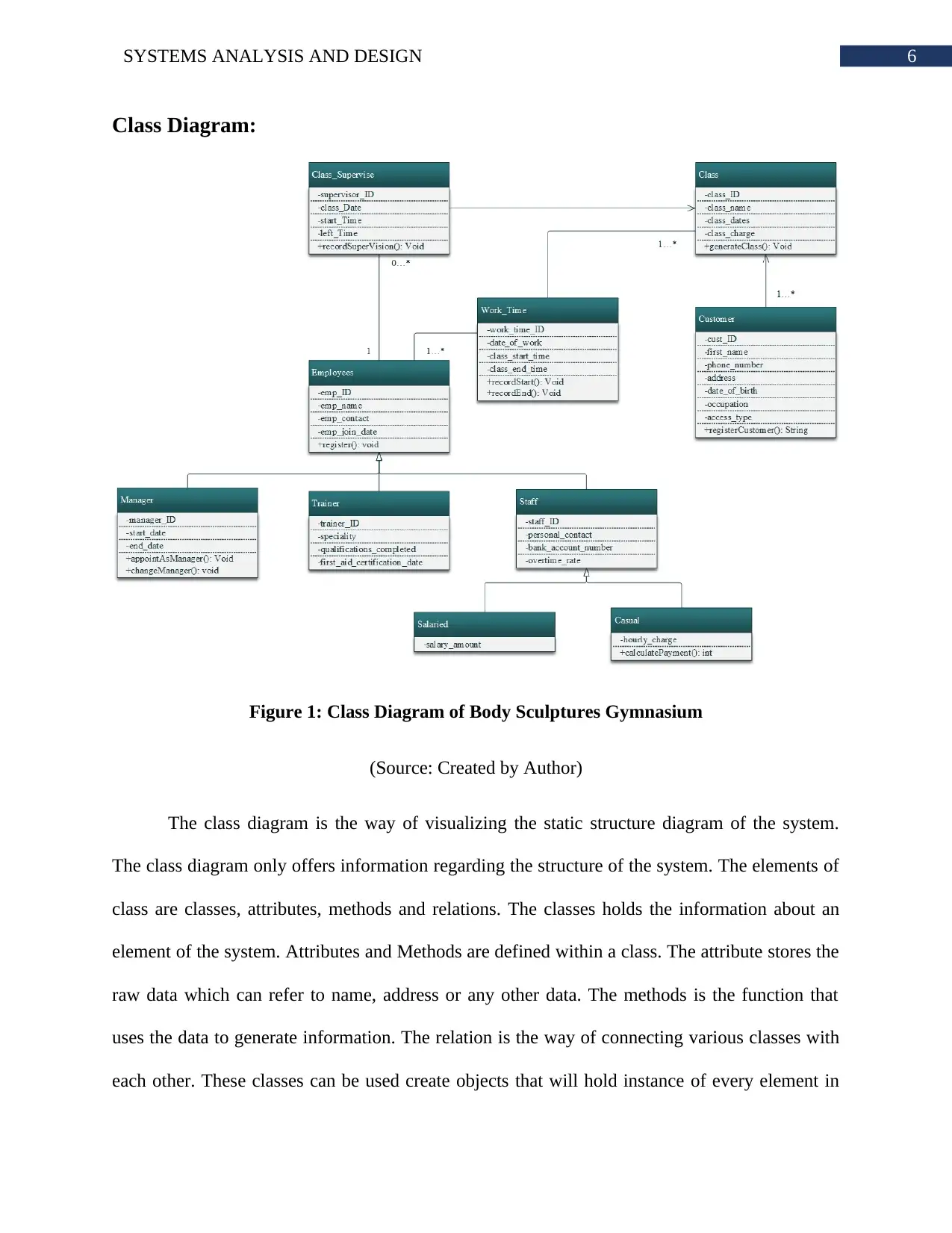
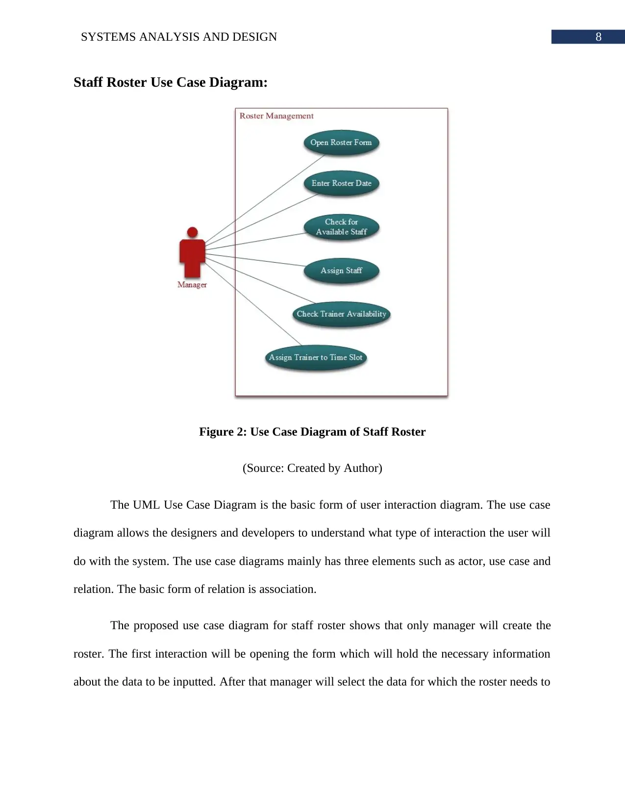
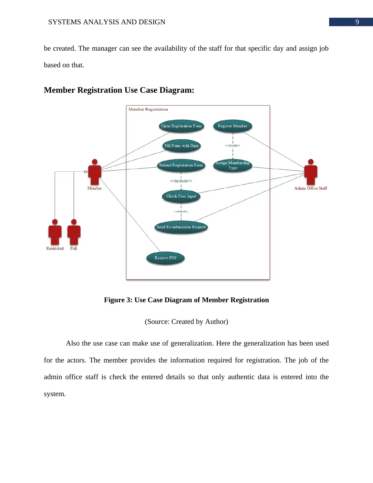
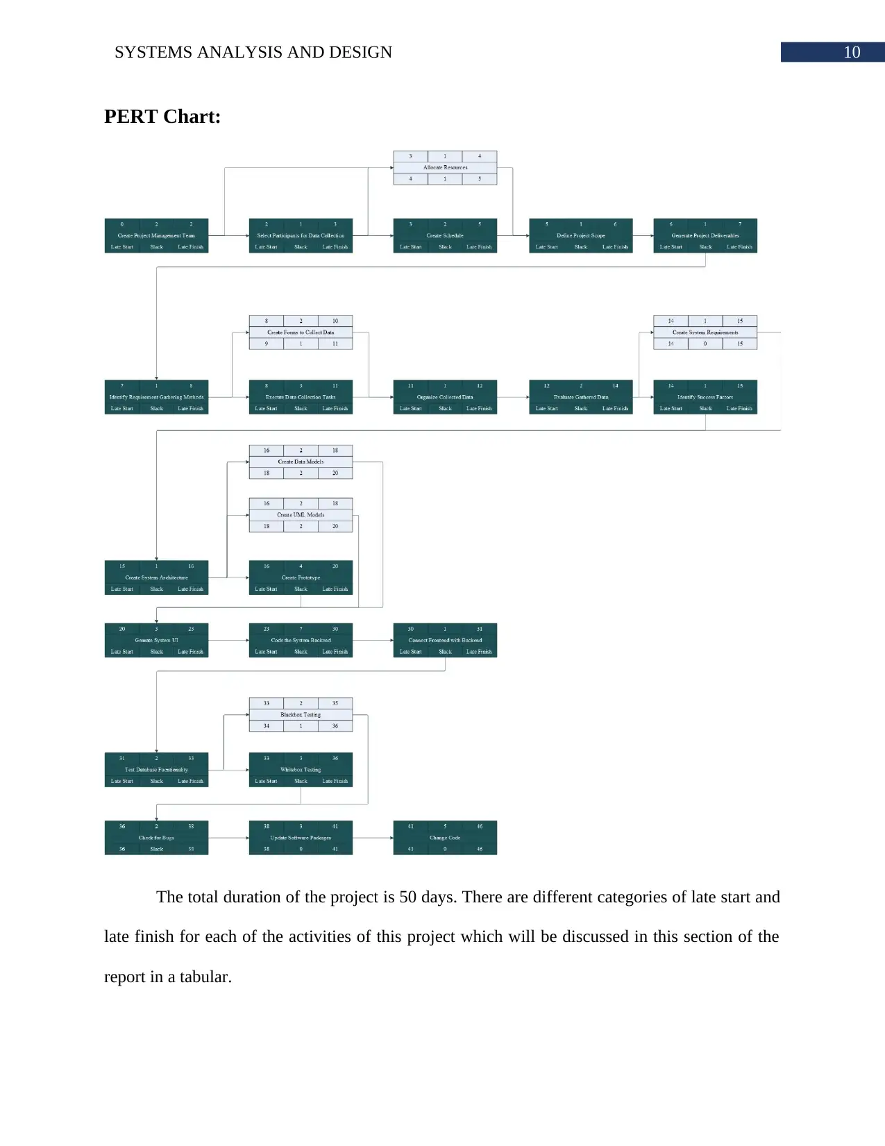
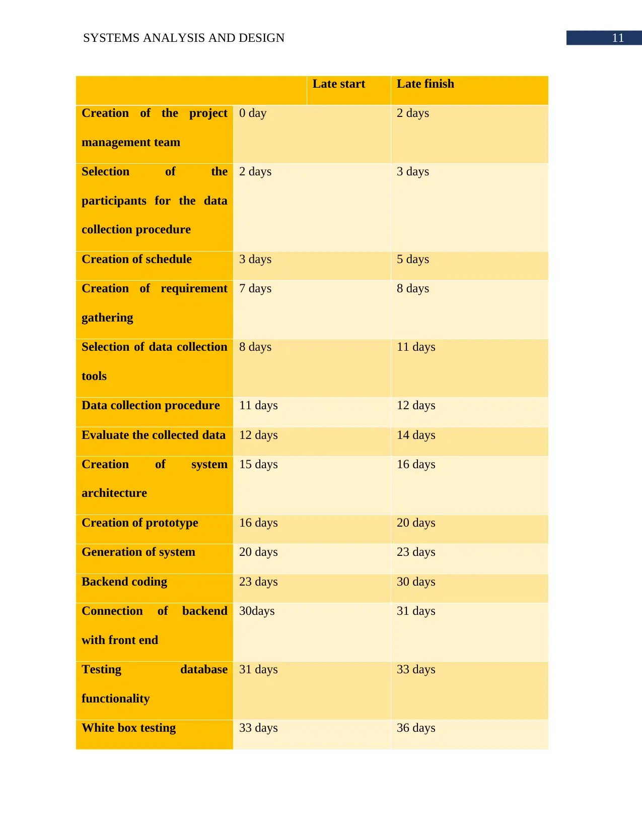
This report provides a comprehensive systems analysis and design for a gymnasium, focusing on the development of a facility management system. It begins with an introduction to the Software Development Lifecycle (SDLC) and its application to the Body Sculptures Gymnasium, outlining the benefits of both Agile and Traditional approaches. The report then details the six core phases of the SDLC: Planning, Defining, Designing, Building, Testing, and Deployment, explaining the activities, stakeholders, and potential challenges within each phase. UML diagrams are used to visualize the system's structure and behavior, including a class diagram that represents the static structure with classes for employees, customers, and their relationships. Use case diagrams illustrate the dynamic interactions, such as staff roster management and member registration. A PERT chart is included to visualize the project timeline, showing task dependencies and durations, to identify the critical path and the overall project duration. The conclusion summarizes the benefits of the proposed system and its efficiency in managing organizational processes. The report provides a detailed analysis of the system and its components.

Running head: SYSTEMS ANALYSIS AND DESIGN
Systems Analysis and Design
Name of the Student
Name of the University
Author’s Note:
Systems Analysis and Design
Name of the Student
Name of the University
Author’s Note:
Paraphrase This Document
Need a fresh take? Get an instant paraphrase of this document with our AI Paraphraser

1SYSTEMS ANALYSIS AND DESIGN
Table of Contents
Introduction:....................................................................................................................................2
SDLC Phases:..................................................................................................................................2
Class Diagram:.................................................................................................................................6
Staff Roster Use Case Diagram:......................................................................................................8
Member Registration Use Case Diagram:.......................................................................................9
PERT Chart:...................................................................................................................................10
Conclusion:....................................................................................................................................12
Bibliography:.................................................................................................................................13

2SYSTEMS ANALYSIS AND DESIGN
Introduction:
The Software Development Lifecycle is the collection of processes that allows an
organization to complete a software development project with total control and monitoring. The
SDLC can be divided into two categories such as Agile and Traditional. UML diagram refers to
the modelling of object oriented elements of a system. The class diagram visualizes the structural
pattern of the system. On the other hand, the use case refers to the dynamic nature of the system.
PERT chart allows identifying the longest path of the planned tasks of project.
The assignment is based on the case information of the Body Sculptures Gymnasium.
The SDLC phases will describe how the system can be developed. The class and use case will
provide information on the systems structural and dynamic pattern.
SDLC Phases:
The development of the facility management system for a gymnasium can follow the six
core processes of software development life cycle which will be discussed in a detailed manner
in this section of the report. The diverse core process of software development life cycle which
must be considered by the designers and the developers of the new systems are listed as follows:
Planning: Identification of the issues and problem areas of the organization and getting
the approval regarding the development of the new system. There are diver categories of
difficulties which are faced by this gymnasium in terms of managing the activities of each of the
staffs who works in this organization like managers, administrators and staffs. Each of the staffs
of this gymnasium has their specific task schedules which have to be managed using the new
facility management system (Abrahamsson et al. 2017). Rostering of shift for each of the staffs
of this gym was a huge issue for the management team of this organization which can be
⊘ This is a preview!⊘
Do you want full access?
Subscribe today to unlock all pages.

Trusted by 1+ million students worldwide

3SYSTEMS ANALYSIS AND DESIGN
managed and administered in an organized manner using the new system. Maintaining the
facilities and equipment in this gym was a huge challenge for the governing bodies of the gym
which can be minimised using the new facility management system. Each number of participant
and the duration of activities associated with each of the staffs can also be managed using the
new system (Allen and Ghareb 2015). Thus, planning phase is the first phase of software
development life cycle which helps in understand the problem areas of gymnasium. The cost and
resources associated in each phase of this project can be identified in the first place using this
phase of SDLC.
Defining: Defining the role of each of the stakeholders who are supposed to work in this
software development project is the prime functionality of the defining phase (Sharma and Misra
2017). There are diverse categories of stakeholders who will be involved in this projects like the
internal stakeholders and the external stakeholders. The internal stakeholders of this project are
the managers of the gymnasium, trainers, administrative staffs of both day and night shift, and
facility manager (Schlegel et al. 2015). The external stakeholders of this project includes the
consumers who are the prime stakeholders of this project along with that the activities of the
software designers, software developers, software testers and the server personals. Defining the
role of each of the associated stakeholders associated with the facility management system is
very much significant in order to maintain the transparency of the project right from the initial
phase of the project to the final phase of the project. Any sort of confusion between each of the
stakeholders can be avoided using this phase of SDLC.
Designing: Being one of the most of the significant part of SDLC, designing phase is
very much useful to understand the features of the facility management system from the
perspective of a designer. Designing the product architecture is considered in this phase of SDLC
Paraphrase This Document
Need a fresh take? Get an instant paraphrase of this document with our AI Paraphraser

4SYSTEMS ANALYSIS AND DESIGN
(Stark 2015). Documentation of this project will be very much significant for the successful
completion of the project and documentation is one of the prime aspect of this phase of SDLC.
Approval from each of the stakeholders are very much required in this phase of SDLC. Each of
the risks associated with the stakeholders has to be identified in the first place using the risk
management procedures and protocols (Matharu et al. 2015). These risks are also included in this
phase of SDLC, robustness of each of the activities can be predicted in this phase of the project.
Design modularity and the diverse categories of constraints associated with the project can also
be identified in the design phase of SDLC.
Building phase: Being the most significant part of SDLC, this phase is very much useful
to maintain the expected outcome of the facility management system. Development of the IT
infrastructure, development of the database and source codes are the prime characteristic features
of this phase of SDLC. The blueprint of the IT infrastructure can be understood in the first place
in this phase (Lewis 2017). The creation of the entire facility management system will start and
finish in this phase of SDLC. The role of the complier, interpreter and debuggers are very much
useful in this phase of SDLC. The quality of standard which has to be maintain regarding the
deployment of a facility management system in a gym can be maintained using the building
phase of SDLC. The final outcome of this project us very much done on this phase of SDLC.
The role of the developers is very much significant for the development of the facility
management system in SDLC.
Testing phase: The development of a new system for a business environment has diverse
categories of risks associated with it in terms of the strategic risks and operations risks. Each of
these categories of risks can have a huge impact on the final outcome of the project. All these
risks are the prime reason behind the significance of this phase of SDLC. Testing phase can be

5SYSTEMS ANALYSIS AND DESIGN
very much significant to understand the diverse categories of errors. Each unit of this facility
management system can be examined and evaluated during integration testing, interface testing
and system testing (Islam, Ponnambalam and Lam 2016). There are diverse categories of testers
who can be involved in this project such as the white box testers and the black box testers. The
internal stakeholders of this project like the managers, administrators of the gym can be the black
box testers of this new system whereas the external stakeholders of this project like the
developers and designers can be the white box testers of this project
Deployment: Deployment is one of the prime aspect of SDLC where the end product is
deployed in the gymnasium. There should not be any sort of errors in the deployment phase of
the facility management system in the gymnasium (Fitzgerald and Stol 2017). Innovative
measures can be very much useful to understand the potential needs of the stakeholders of the
project (Butterfield et al. 2016). Each of the activities of the new facility management has to be
aligned with the daily activities of the gym in terms of the managing the shift hour of each of the
resources which works in this project and management of the equipment which are already there
in the premises.
⊘ This is a preview!⊘
Do you want full access?
Subscribe today to unlock all pages.

Trusted by 1+ million students worldwide

6SYSTEMS ANALYSIS AND DESIGN
Class Diagram:
Figure 1: Class Diagram of Body Sculptures Gymnasium
(Source: Created by Author)
The class diagram is the way of visualizing the static structure diagram of the system.
The class diagram only offers information regarding the structure of the system. The elements of
class are classes, attributes, methods and relations. The classes holds the information about an
element of the system. Attributes and Methods are defined within a class. The attribute stores the
raw data which can refer to name, address or any other data. The methods is the function that
uses the data to generate information. The relation is the way of connecting various classes with
each other. These classes can be used create objects that will hold instance of every element in
Paraphrase This Document
Need a fresh take? Get an instant paraphrase of this document with our AI Paraphraser

7SYSTEMS ANALYSIS AND DESIGN
the system. If the system wants to work with more than one employee then the two instance of
the classes will be used.
The proposed class diagram has five main classes. Generalization has been used in the
diagram to show parent-child relation. The generalization is implemented when a class can be
decomposed into at least two classes and both the classes share some common attributes and
methods. The employee parent class has three child classes such as manager, trainer and staff.
The staff class has been decomposed into two child classes such as salaried and casual. The
difference between salaried and casual is the type of payment they get. The work time has one-
to-many relation with the employee and class. This class acts like a bridge class between the
employee and class. The customer class has also generalization which visualize the child classes
full and restricted. Class_Supervise and Class has direct association between those classes.
Direct association refers to navigation to only one direction.

8SYSTEMS ANALYSIS AND DESIGN
Staff Roster Use Case Diagram:
Figure 2: Use Case Diagram of Staff Roster
(Source: Created by Author)
The UML Use Case Diagram is the basic form of user interaction diagram. The use case
diagram allows the designers and developers to understand what type of interaction the user will
do with the system. The use case diagrams mainly has three elements such as actor, use case and
relation. The basic form of relation is association.
The proposed use case diagram for staff roster shows that only manager will create the
roster. The first interaction will be opening the form which will hold the necessary information
about the data to be inputted. After that manager will select the data for which the roster needs to
⊘ This is a preview!⊘
Do you want full access?
Subscribe today to unlock all pages.

Trusted by 1+ million students worldwide

9SYSTEMS ANALYSIS AND DESIGN
be created. The manager can see the availability of the staff for that specific day and assign job
based on that.
Member Registration Use Case Diagram:
Figure 3: Use Case Diagram of Member Registration
(Source: Created by Author)
Also the use case can make use of generalization. Here the generalization has been used
for the actors. The member provides the information required for registration. The job of the
admin office staff is check the entered details so that only authentic data is entered into the
system.
Paraphrase This Document
Need a fresh take? Get an instant paraphrase of this document with our AI Paraphraser

10SYSTEMS ANALYSIS AND DESIGN
PERT Chart:
The total duration of the project is 50 days. There are different categories of late start and
late finish for each of the activities of this project which will be discussed in this section of the
report in a tabular.
PERT Chart:
The total duration of the project is 50 days. There are different categories of late start and
late finish for each of the activities of this project which will be discussed in this section of the
report in a tabular.

11SYSTEMS ANALYSIS AND DESIGN
Late start Late finish
Creation of the project
management team
0 day 2 days
Selection of the
participants for the data
collection procedure
2 days 3 days
Creation of schedule 3 days 5 days
Creation of requirement
gathering
7 days 8 days
Selection of data collection
tools
8 days 11 days
Data collection procedure 11 days 12 days
Evaluate the collected data 12 days 14 days
Creation of system
architecture
15 days 16 days
Creation of prototype 16 days 20 days
Generation of system 20 days 23 days
Backend coding 23 days 30 days
Connection of backend
with front end
30days 31 days
Testing database
functionality
31 days 33 days
White box testing 33 days 36 days
⊘ This is a preview!⊘
Do you want full access?
Subscribe today to unlock all pages.

Trusted by 1+ million students worldwide
1 out of 15
Related Documents

Your All-in-One AI-Powered Toolkit for Academic Success.
 +13062052269
info@desklib.com
Available 24*7 on WhatsApp / Email
Unlock your academic potential
Copyright © 2020–2025 A2Z Services. All Rights Reserved. Developed and managed by ZUCOL.