SCDM71-316: Structural Analysis of Brock Commons Tallwood House Report

Verified

Added on  2023/06/03

|42
|5180
|347
Report
AI Summary
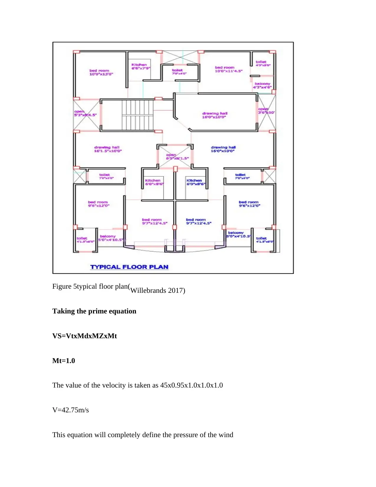
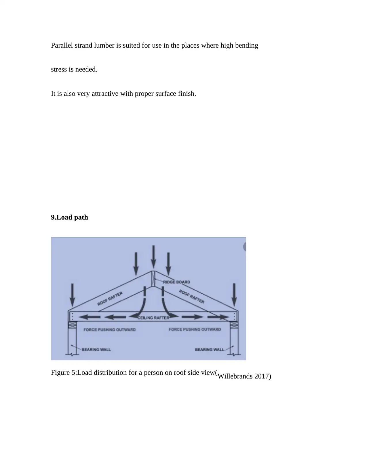
This report provides a comprehensive analysis of the Brock Commons Tallwood House, a 13-story wooden structure, considering its construction, materials, and structural design. The report begins with an introduction to the building, highlighting its unique features and the use of timber. It then delves into detailed calculations of dead loads on various floors, including the roof, using assumed values and formulas. The report further explores dynamic load calculations, specifically wind load, considering factors like wind velocity and pressure. Durability, fire protection, and the reasoning behind material choices (GLT and PSL) are also discussed. The load path, building stability, and the use of concrete shear walls are examined, along with considerations for earthquake resistance. The report also covers tributary areas in vertical elements, connections, and geotechnical testing methods such as direct shear, Proctor compaction, and triaxial shear tests. Finally, the report explores various aspects of the building's design, including connections and geotechnical testing, providing a holistic overview of the structural and soil mechanics considerations involved in the building's design and construction.
Document Page
SCDM71-316 STRUCTURES AND SOIL MECHANICS
[Author Name(s), First M. Last, Omit Titles and Degrees]
[Institutional Affiliation(s)]
Question 1
tabler-icon-diamond-filled.svg

Paraphrase This Document

Need a fresh take? Get an instant paraphrase of this document with our AI Paraphraser
Document Page
The Brock Commons house has already been considered the tallest wood construction in the North
America. The structure is 13-storey that is found in the Pointe-aux-Lièvre’s eco-neighborhood in
the city of Quebec. The tall solid timber structure has been constructed on the podium made of
concrete/.The structure is 134 feet in its height. The structure is unique by the fact that it is made up
of entirely the solid wood(Su 2018). The wooden structure is found in the staircases and also in the
shafts of the elevator. The exterior walls and the cross are also made of the wooden components.
The structure is a combination of the glulam beams and columns and also the CLT columns. The
chance that has been created by the new, larger and the taller building made of wood has been
recognized as an option that is viable in the country especially by the building and the design
community(Al-Mukhtar, Khattab and Alcover 2012). The process has been made possible by the
evolution of the products of the woods. The approach and the philosophy of the entire project was
basically to use the materials in the most recommended way that allowed for the achievement of the
hybrid system of concrete cores and timber.
Question 2
Dead loads on respective floors.
Document Page
Figure 1:Loading of the structure (Willebrands 2017)
Figure 2:Dead loads on the structure from the roof made of Iron sheets(Willebrands 2017.).
L
1
L
L
2
Document Page
Figure 3:Dead loads on the structure made of timber(Willebrand 2017)
Question 3
1st Storey:
3a)Dead Load:
Assumption: It is assumed that slab to be non-suspended slab
Floor system = 0.75 kPa (assumed) x (6/2 + 4/2) x (5.6/2 + 4.4/2) = 18.75 kN Column
= 0.45 x 0.4 x 4.75 x 24 = 20.52 kN
Wall unit = 20 x 0.175 x (6/2 + 4/2) x 4.75 = 83.13 kN
Overall = 121.4 kN
3b)Second Storey:
tabler-icon-diamond-filled.svg

Paraphrase This Document

Need a fresh take? Get an instant paraphrase of this document with our AI Paraphraser
Document Page
Dead Load:
Slab = 0.15m (assumed) x 24 x (6/2 + 4/2) x (5.6/2 + 4.4/2) = 90 kN Floor
system = 0.75 kPa (assumed) x (6/2 + 4/2) x (5.6/2 + 4.4/2) = 18.75 kN Column =
0.45 x 0.4 x 3.46 x 24 = 15 kN wall system = 20
x 0.175 x (6/2 + 4/2) x (5.6/2 + 4.4/2) = 60.55 Primary Beam = 24 x
0.6m x 0.8m x (6/2 + 4/2) = 57.6 kN
Secondary Beam = 24 x 0.25 x 0.45 x (6/2 + 4/2) = 13.5 kN
Overall = 256.4 kN
Live Load:
LL = 4 KN//m2 (assumed) x (6/2 + 4/2) x (5.6/2 + 4.4/2) = 100 kN
2nd upper or Third storey
(i) Dead Load:
system Slab = 0.15m (assumed) x 24 x (6/2 + 4/2) x (5.6/2) = 51.4 kN
Beam = 24 x 0.6m x 0.8m x 6 = 68.1 KN
Floor system = 0.75 kPa (assumed) x (6/2 + 4/2) x (5.6/2) = 10.5 kN
Column = 0.45 x 0.4 x 3.06 x 24 = 12.22 kN
wall system = 20 x 0.175 x (6/2 + 4/2) x 3.06 = 54.55 kN
Document Page
Overall = 197.77 kN
(ii) Live Load: (2nd Upper Storey Rooms)
LL = 4 KN/m2 (assumed) x (6/2 + 4/2) x (5.6/2) = 50 kN
Document Page
(2d) Roof Level:
Wall unit = 20 x 0.175 x 1.81 x (6/2 + 4/2) =32 kN Dead Load service
= 0.75 kPa (assumed) x (5.6/2 + 4.4/2) x (6/2 + 4/2) = 18.75 kN
Overall = 53.75 kN
Dead Loads of roof = 0.75KN/m2 x 5 x 5 = 14.17
Roof Materials kN = 1.5KN//m2 x 5 x 5 = 57.25 KN
Summation of Dead Load = 122.4 + 255.4 + 197.77 + 51.75 + 56.25 = 682.57 kN
Footing strip Size of 2m width (instead of 4m) x 4m (range Length) x .75mm thick
Weight of Ground Footing Foundation = 24.0 x 2 x 4 x .75 =145.0 KN
Soil Pressure force = 989.64 / (2.0 x 4.0) = 124.71 KN//m2
5. Dynamic load calculation
The provided spacing is ta the interval of 20feet
=20ft
=20x0.305
=6.1m
tabler-icon-diamond-filled.svg

Paraphrase This Document

Need a fresh take? Get an instant paraphrase of this document with our AI Paraphraser
Document Page
The height of the colum will be taken as 5.9 metres
The pitch of the roof will bwe taken as 27 degrees
H(roof)=5.9+6.63X TAN 27
=9.28M.
The average height will be calculated as
h=5.9+9.28-5.9/2=7.6m
The working life obtained becomes 50 years
The region becomes A4
The equivalent VR=45m/s for the ultimate loading. And also 37m/s for
serviceability.
.
4. Live load plan
Document Page
Figure 5typical floor plan(Willebrands 2017)
Taking the prime equation
VS=VtxMdxMZxMt
Mt=1.0
The value of the velocity is taken as 45x0.95x1.0x1.0x1.0
V=42.75m/s
This equation will completely define the pressure of the wind
Document Page
=37x0.97
=35.15m/assuming that the density of the air remain the same as 1.2kg/m3
and also taking the factor of the dynamic loading to be constant that is;
C=1.0
P=0.5x1.2x42.75x42.75x1/1000
=1.097(This is described as Ultimate limit)
The internal pressure will translates into the cross wind
K=0.8 for the cross wind.
Pressure becomes; 1.097x (-0.24) remember -0.24 was obtained from -
0.3x0.8
P=-1.61kN/m.
For upward slope
P=-.4x1.097
=-0.44kPa
6. Durability
Steel is normally affected by the process of the corrosion. This can be
tabler-icon-diamond-filled.svg

Paraphrase This Document

Need a fresh take? Get an instant paraphrase of this document with our AI Paraphraser
Document Page
controlled by the use of the galvanic corrosion protection. The concrete may
be affected by improper compaction and other ASR effects. The effects of
ASR(Alkali Silica Reaction) can be prevented using pozzolanic admixtures.
Timber is affected by exposure to water. This should be minimized as low
as possible.
7. Fire protection.
The building has employed the use of the timber with the thick layer. This
thick layer normally chars to provide natural protection against protection of
fire. The building also enjoys access to the fire extinguishers and
standpipes(Willebrands, O., 2017)..
8. Reasoning behind GLT and PSL
The GLT has excellent strength to weight ratio
It is durable
It poses proper flexibility to size and shape
It has high dimensional stability and strength besides being locally
available.
Document Page
Parallel strand lumber is suited for use in the places where high bending
stress is needed.
It is also very attractive with proper surface finish.
9.Load path
Figure 5:Load distribution for a person on roof side view(Willebrands 2017)
chevron_up_icon
1 out of 42
circle_padding
hide_on_mobile
zoom_out_icon
[object Object]