Electrical Engineering Report: BLDC Motor Design and Function
VerifiedAdded on 2022/12/23
|8
|1266
|63
Report
AI Summary
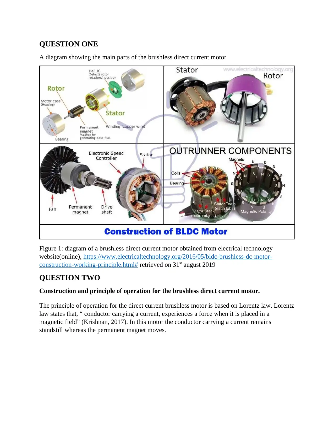
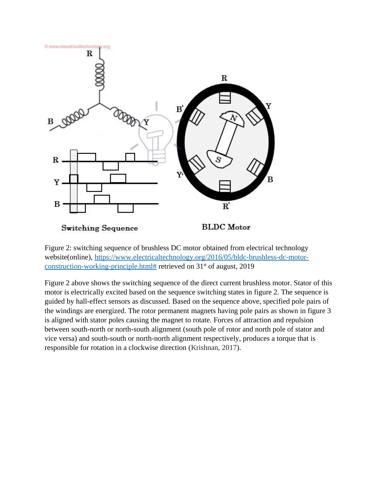
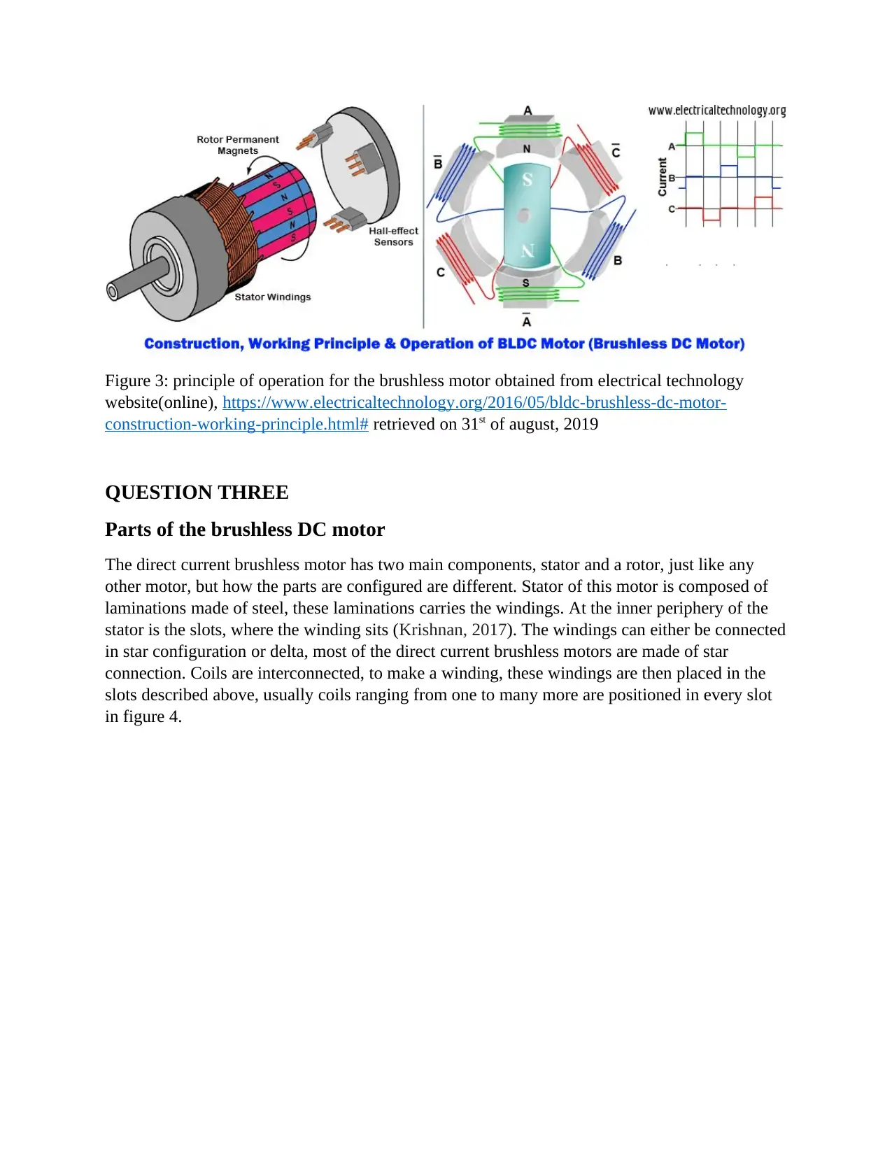
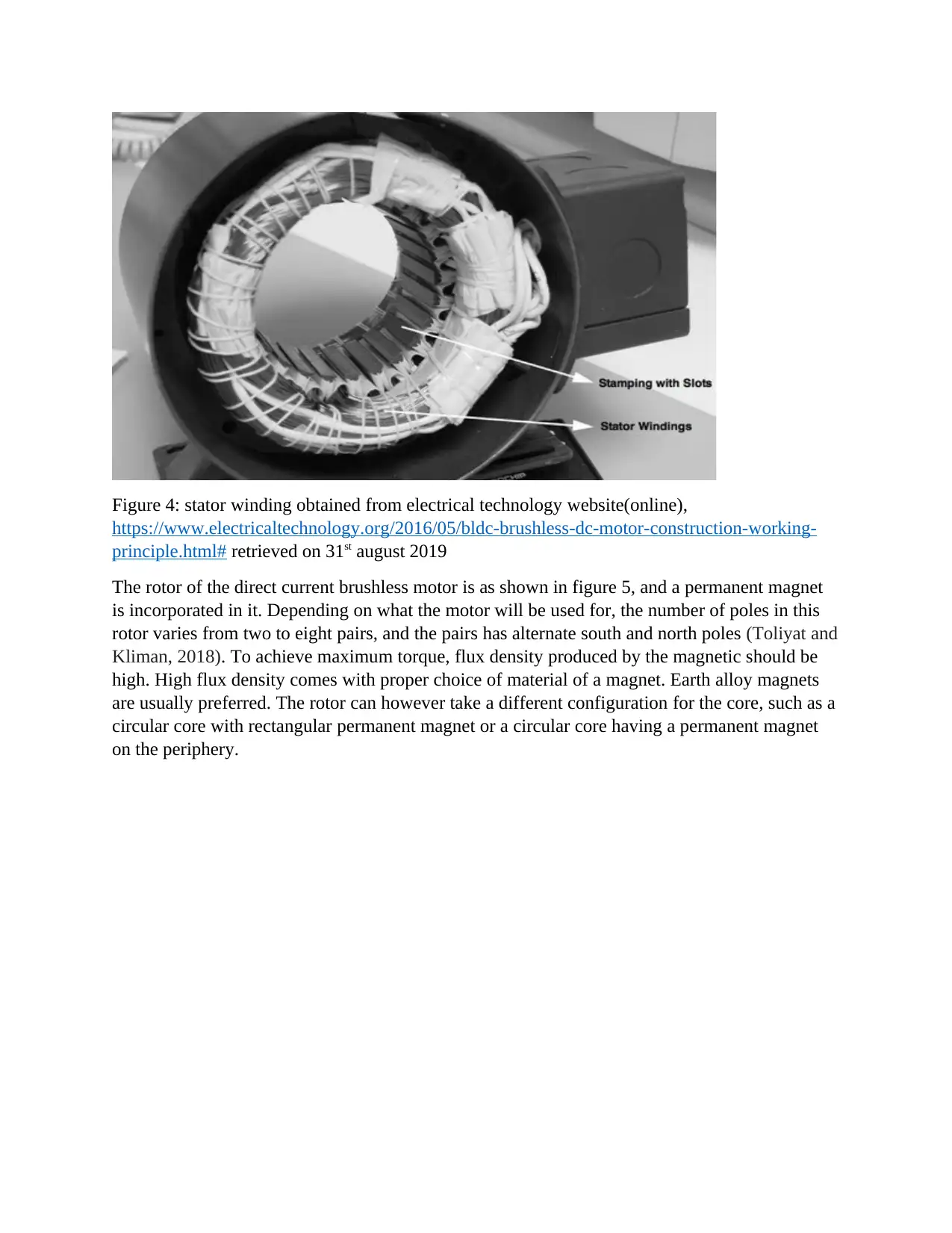
This report delves into the intricacies of Brushless DC (BLDC) motors, covering their construction, working principles, and operational characteristics. The report begins with a diagram illustrating the main components of a BLDC motor and then proceeds to explain the principle of operation based on Lorentz law, detailing the role of the stator, rotor, and Hall sensors in achieving electrical commutation. It further elaborates on the construction of the motor, highlighting the stator's windings and the rotor's permanent magnet configuration. The report also differentiates between BLDC motors and other types of motors, emphasizing their high operating speed, efficiency, and compact size. Finally, it discusses the two main types of BLDC motors, inner rotor and outer rotor, and provides relevant references to support the information presented. This report serves as a comprehensive resource for understanding the design, function, and application of BLDC motors.

QUESTION ONE
A diagram showing the main parts of the brushless direct current motor
Figure 1: diagram of a brushless direct current motor obtained from electrical technology
website(online), https://www.electricaltechnology.org/2016/05/bldc-brushless-dc-motor-
construction-working-principle.html# retrieved on 31st august 2019
QUESTION TWO
Construction and principle of operation for the brushless direct current motor.
The principle of operation for the direct current brushless motor is based on Lorentz law. Lorentz
law states that, “ conductor carrying a current, experiences a force when it is placed in a
magnetic field” (Krishnan, 2017). In this motor the conductor carrying a current remains
standstill whereas the permanent magnet moves.
Paraphrase This Document
Need a fresh take? Get an instant paraphrase of this document with our AI Paraphraser

Figure 2: switching sequence of brushless DC motor obtained from electrical technology
website(online), https://www.electricaltechnology.org/2016/05/bldc-brushless-dc-motor-
construction-working-principle.html# retrieved on 31st of august, 2019
Figure 2 above shows the switching sequence of the direct current brushless motor. Stator of this
motor is electrically excited based on the sequence switching states in figure 2. The sequence is
guided by hall-effect sensors as discussed. Based on the sequence above, specified pole pairs of
the windings are energized. The rotor permanent magnets having pole pairs as shown in figure 3
is aligned with stator poles causing the magnet to rotate. Forces of attraction and repulsion
between south-north or north-south alignment (south pole of rotor and north pole of stator and
vice versa) and south-south or north-north alignment respectively, produces a torque that is
responsible for rotation in a clockwise direction (Krishnan, 2017).

Figure 3: principle of operation for the brushless motor obtained from electrical technology
website(online), https://www.electricaltechnology.org/2016/05/bldc-brushless-dc-motor-
construction-working-principle.html# retrieved on 31st of august, 2019
QUESTION THREE
Parts of the brushless DC motor
The direct current brushless motor has two main components, stator and a rotor, just like any
other motor, but how the parts are configured are different. Stator of this motor is composed of
laminations made of steel, these laminations carries the windings. At the inner periphery of the
stator is the slots, where the winding sits (Krishnan, 2017). The windings can either be connected
in star configuration or delta, most of the direct current brushless motors are made of star
connection. Coils are interconnected, to make a winding, these windings are then placed in the
slots described above, usually coils ranging from one to many more are positioned in every slot
in figure 4.
⊘ This is a preview!⊘
Do you want full access?
Subscribe today to unlock all pages.

Trusted by 1+ million students worldwide

Figure 4: stator winding obtained from electrical technology website(online),
https://www.electricaltechnology.org/2016/05/bldc-brushless-dc-motor-construction-working-
principle.html# retrieved on 31st august 2019
The rotor of the direct current brushless motor is as shown in figure 5, and a permanent magnet
is incorporated in it. Depending on what the motor will be used for, the number of poles in this
rotor varies from two to eight pairs, and the pairs has alternate south and north poles (Toliyat and
Kliman, 2018). To achieve maximum torque, flux density produced by the magnetic should be
high. High flux density comes with proper choice of material of a magnet. Earth alloy magnets
are usually preferred. The rotor can however take a different configuration for the core, such as a
circular core with rectangular permanent magnet or a circular core having a permanent magnet
on the periphery.
Paraphrase This Document
Need a fresh take? Get an instant paraphrase of this document with our AI Paraphraser

Figure 5: rotor of a brushless DC motor obtained from electrical technology website(online),
https://www.electricaltechnology.org/2016/05/bldc-brushless-dc-motor-construction-working-
principle.html# retrieved on 31st of August 2019
Another component making up the direct current brushless motor is the hall sensors. The hall
sensor is used to provide information that helps in synchronization of armature excitation with
the rotor. The direct current brushless motor, from it’s name has zero brushes, and the
commutation in this motor is electronically controlled, to achieve this stator winding has to be
energized in a specified pattern or sequence, so as to cause a rotation(El-Samahy and
Shamseldin, 2018). To determine which winding to be energized, rotor position has to be known.
The hall sensor does this job, to determine the position of the rotor. Most motors use three hall
sensors, the three sensors produce signals whenever a pole passes nearby. The three sensors
together, works to achieve electrical commutation. Figure 6 below shows how hall sensors, stator
and rotor of brushless direct current are placed.

Figure 6: main components of brushless DC motor, obtained from electrical technology
website(online), https://www.electricaltechnology.org/2016/05/bldc-brushless-dc-motor-
construction-working-principle.html# retrieved on 31st of August 2019
QUESTION FOUR
How is brushless DC different from other motors?
Direct current brushless motor is different from direct current brushed motor, in that the earlier
has high operating speed and efficiency. Furthermore, brushless DC motor dissipates heat better
compared to direct current brushed motor.
In direct current brushed motor, there is a direct mechanical contact of motor brushes with the
commutator. In the contrary, the direct current brushless motor uses a sequence of coils to
achieve electrical commutation with the stator and the rotor. The electrical commutation
employed in direct current brushless motor makes the motor less noisy and reliable. The
commutation also makes the motor run at a higher speed (electrical technology, n.d).
Due to the small geometry of brushless, it is lighter as compared to any other motor, and this
makes it applied in robotics among other applications that require small size components.
Brushless DC motor uses complex drive circuitry for its control as compared to other motors.
The control circuit provides pulses of signals to winding to control the speed and torque of the
motor
⊘ This is a preview!⊘
Do you want full access?
Subscribe today to unlock all pages.

Trusted by 1+ million students worldwide

Due to the absence of brushes, brushless motor has a longer lifetime as the maintenance and
inspection is minimal
QUESTION FIVE
There are two main types of brushless DC motor namely inner rotor motor and outer rotor motor
(Lee, Seo, Kim and Jung, 2016). The two types work on the same principle, the only difference
is in its design.
inspection is minimal
QUESTION FIVE
There are two main types of brushless DC motor namely inner rotor motor and outer rotor motor
(Lee, Seo, Kim and Jung, 2016). The two types work on the same principle, the only difference
is in its design.
Paraphrase This Document
Need a fresh take? Get an instant paraphrase of this document with our AI Paraphraser

REFERENCES
Electrical technology, n.d, brushless DC motor (BLDC)-construction, working principle &
applications, available in https://www.electricaltechnology.org/2016/05/bldc-brushless-dc-
motor-construction-working-principle.html# [31 July 2019]
El-Samahy, A.A. and Shamseldin, M.A., 2018. Brushless DC motor tracking control using self-
tuning fuzzy PID control and model reference adaptive control. Ain Shams Engineering
Journal, 9(3), pp.341-352.
Krishnan, R., 2017. Permanent magnet synchronous and brushless DC motor drives. CRC press.
Lee, T.Y., Seo, M.K., Kim, Y.J. and Jung, S.Y., 2016. Motor design and characteristics
comparison of outer-rotor-type BLDC motor and BLAC motor based on numerical
analysis. IEEE Transactions on Applied Superconductivity, 26(4), pp.1-6.
Nishidate, M., Tokyo Parts Ind Co Ltd, 2017. Brushless DC motor. U.S. Patent 9,716,418.
Toliyat, H.A. and Kliman, G.B. eds., 2018. Handbook of electric motors (Vol. 120). CRC press.
1 out of 8
Related Documents

Your All-in-One AI-Powered Toolkit for Academic Success.
+13062052269
info@desklib.com
Available 24*7 on WhatsApp / Email
Unlock your academic potential
Copyright © 2020–2025 A2Z Services. All Rights Reserved. Developed and managed by ZUCOL.