Comprehensive Analysis: BLDC Motor Speed Control Techniques Report

Verified

Added on  2022/10/19

|8
|1344
|16
Report
AI Summary
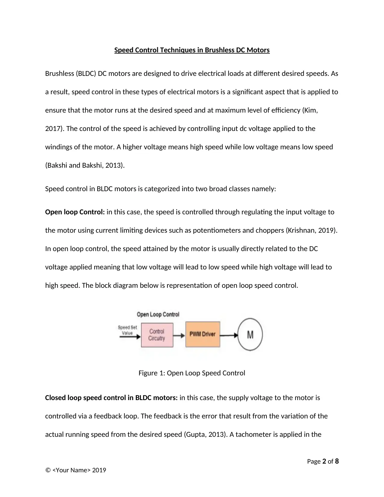
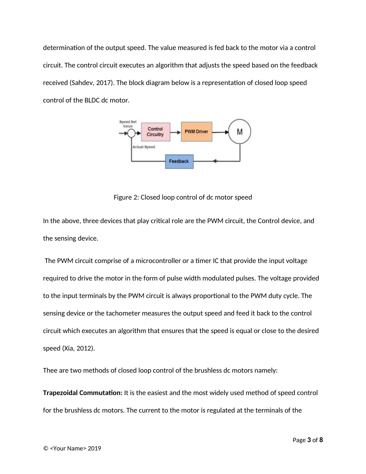
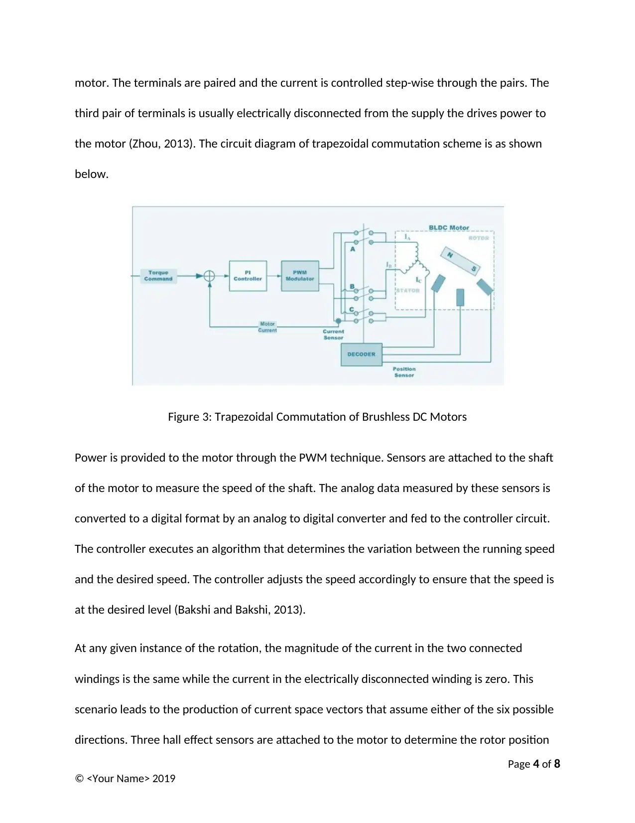
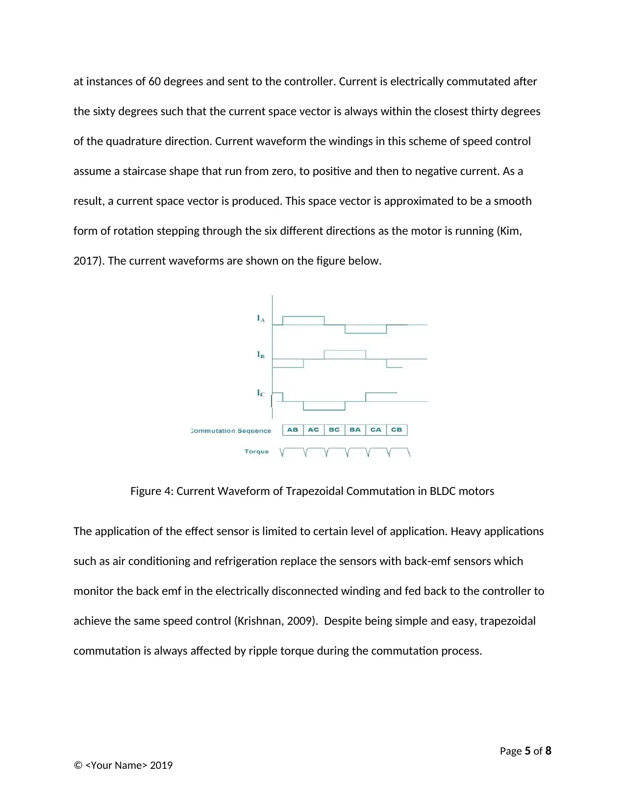
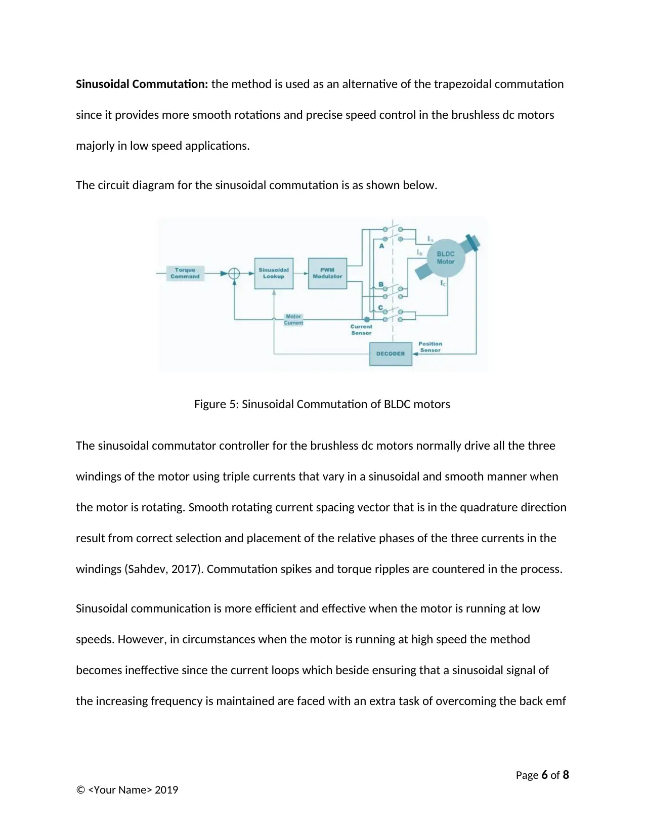
This report delves into the crucial aspect of speed control in Brushless DC (BLDC) motors, essential for efficient operation at desired speeds. The report categorizes speed control into open-loop and closed-loop systems, detailing their respective mechanisms and applications. Open-loop control, achieved by regulating input voltage, is contrasted with closed-loop control, which utilizes feedback loops and devices like tachometers to maintain precise speed regulation. Furthermore, the report examines two primary closed-loop control methods: trapezoidal commutation, the most common approach, and sinusoidal commutation, preferred for smoother rotations, especially at low speeds. The report includes circuit diagrams and current waveforms to illustrate these techniques, along with their advantages and limitations, such as ripple torque in trapezoidal commutation and the effectiveness of sinusoidal commutation at low speeds. References are provided for further reading.
Document Page
University
Speed Control Techniques in Brushless DC Motors
By
Your Name
Date
Page 1 of 8
© <Your Name> 2019
tabler-icon-diamond-filled.svg

Paraphrase This Document

Need a fresh take? Get an instant paraphrase of this document with our AI Paraphraser
Document Page
Speed Control Techniques in Brushless DC Motors
Brushless (BLDC) DC motors are designed to drive electrical loads at different desired speeds. As
a result, speed control in these types of electrical motors is a significant aspect that is applied to
ensure that the motor runs at the desired speed and at maximum level of efficiency (Kim,
2017). The control of the speed is achieved by controlling input dc voltage applied to the
windings of the motor. A higher voltage means high speed while low voltage means low speed
(Bakshi and Bakshi, 2013).
Speed control in BLDC motors is categorized into two broad classes namely:
Open loop Control: in this case, the speed is controlled through regulating the input voltage to
the motor using current limiting devices such as potentiometers and choppers (Krishnan, 2019).
In open loop control, the speed attained by the motor is usually directly related to the DC
voltage applied meaning that low voltage will lead to low speed while high voltage will lead to
high speed. The block diagram below is representation of open loop speed control.
Figure 1: Open Loop Speed Control
Closed loop speed control in BLDC motors: in this case, the supply voltage to the motor is
controlled via a feedback loop. The feedback is the error that result from the variation of the
actual running speed from the desired speed (Gupta, 2013). A tachometer is applied in the
Page 2 of 8
© <Your Name> 2019
Document Page
determination of the output speed. The value measured is fed back to the motor via a control
circuit. The control circuit executes an algorithm that adjusts the speed based on the feedback
received (Sahdev, 2017). The block diagram below is a representation of closed loop speed
control of the BLDC dc motor.
Figure 2: Closed loop control of dc motor speed
In the above, three devices that play critical role are the PWM circuit, the Control device, and
the sensing device.
The PWM circuit comprise of a microcontroller or a timer IC that provide the input voltage
required to drive the motor in the form of pulse width modulated pulses. The voltage provided
to the input terminals by the PWM circuit is always proportional to the PWM duty cycle. The
sensing device or the tachometer measures the output speed and feed it back to the control
circuit which executes an algorithm that ensures that the speed is equal or close to the desired
speed (Xia, 2012).
Thee are two methods of closed loop control of the brushless dc motors namely:
Trapezoidal Commutation: It is the easiest and the most widely used method of speed control
for the brushless dc motors. The current to the motor is regulated at the terminals of the
Page 3 of 8
© <Your Name> 2019
Document Page
motor. The terminals are paired and the current is controlled step-wise through the pairs. The
third pair of terminals is usually electrically disconnected from the supply the drives power to
the motor (Zhou, 2013). The circuit diagram of trapezoidal commutation scheme is as shown
below.
Figure 3: Trapezoidal Commutation of Brushless DC Motors
Power is provided to the motor through the PWM technique. Sensors are attached to the shaft
of the motor to measure the speed of the shaft. The analog data measured by these sensors is
converted to a digital format by an analog to digital converter and fed to the controller circuit.
The controller executes an algorithm that determines the variation between the running speed
and the desired speed. The controller adjusts the speed accordingly to ensure that the speed is
at the desired level (Bakshi and Bakshi, 2013).
At any given instance of the rotation, the magnitude of the current in the two connected
windings is the same while the current in the electrically disconnected winding is zero. This
scenario leads to the production of current space vectors that assume either of the six possible
directions. Three hall effect sensors are attached to the motor to determine the rotor position
Page 4 of 8
© <Your Name> 2019
tabler-icon-diamond-filled.svg

Paraphrase This Document

Need a fresh take? Get an instant paraphrase of this document with our AI Paraphraser
Document Page
at instances of 60 degrees and sent to the controller. Current is electrically commutated after
the sixty degrees such that the current space vector is always within the closest thirty degrees
of the quadrature direction. Current waveform the windings in this scheme of speed control
assume a staircase shape that run from zero, to positive and then to negative current. As a
result, a current space vector is produced. This space vector is approximated to be a smooth
form of rotation stepping through the six different directions as the motor is running (Kim,
2017). The current waveforms are shown on the figure below.
Figure 4: Current Waveform of Trapezoidal Commutation in BLDC motors
The application of the effect sensor is limited to certain level of application. Heavy applications
such as air conditioning and refrigeration replace the sensors with back-emf sensors which
monitor the back emf in the electrically disconnected winding and fed back to the controller to
achieve the same speed control (Krishnan, 2009). Despite being simple and easy, trapezoidal
commutation is always affected by ripple torque during the commutation process.
Page 5 of 8
© <Your Name> 2019
Document Page
Sinusoidal Commutation: the method is used as an alternative of the trapezoidal commutation
since it provides more smooth rotations and precise speed control in the brushless dc motors
majorly in low speed applications.
The circuit diagram for the sinusoidal commutation is as shown below.
Figure 5: Sinusoidal Commutation of BLDC motors
The sinusoidal commutator controller for the brushless dc motors normally drive all the three
windings of the motor using triple currents that vary in a sinusoidal and smooth manner when
the motor is rotating. Smooth rotating current spacing vector that is in the quadrature direction
result from correct selection and placement of the relative phases of the three currents in the
windings (Sahdev, 2017). Commutation spikes and torque ripples are countered in the process.
Sinusoidal communication is more efficient and effective when the motor is running at low
speeds. However, in circumstances when the motor is running at high speed the method
becomes ineffective since the current loops which beside ensuring that a sinusoidal signal of
the increasing frequency is maintained are faced with an extra task of overcoming the back emf
Page 6 of 8
© <Your Name> 2019
Document Page
whose amplitude and frequency also rises with increase in speed (Pyrhonen, Jokinen and
Hrabovcova, 2013).
Page 7 of 8
© <Your Name> 2019
tabler-icon-diamond-filled.svg

Paraphrase This Document

Need a fresh take? Get an instant paraphrase of this document with our AI Paraphraser
Document Page
References
Bakshi, U. A., and Bakshi, M. V. 2013. Electrical drives and control. 2nd ed. Technical Publications.
Gupta, A. 2013. Intelligent control of brushless DC motors for hybrid electric vehicle applications.
Krishnan, R. 2009. Permanent magnet synchronous and brushless DC motor drives. Boca Raton,
FL: CRC Press.
Kim, S. 2017. Electric motor control: DC, AC, and BLDC motors. Amsterdam, Netherlands:
Elsevier.
Pyrhonen, J., Jokinen, T., and Hrabovcova, V. 2013. Design of rotating electrical machines.
Hoboken, NJ: John Wiley & Sons.
Sahdev, S. K. 2017. Electrical machines. 3rd ed. Cambridge, England: Cambridge University Press.
Xia, C. 2012. Permanent magnet brushless DC motor drives and controls. Hoboken, NJ: John
Wiley & Sons.
Zhou, Y. 2013. DC motors, speed controls, and servo systems: An engineering handbook.
Amsterdam, Netherlands: Elsevier.
Page 8 of 8
© <Your Name> 2019
chevron_up_icon
1 out of 8
circle_padding
hide_on_mobile
zoom_out_icon
[object Object]