TECOL BTEC Engineering: PLC Selection and Application (Unit 12)
VerifiedAdded on 2022/10/02
|15
|3167
|29
Homework Assignment
AI Summary
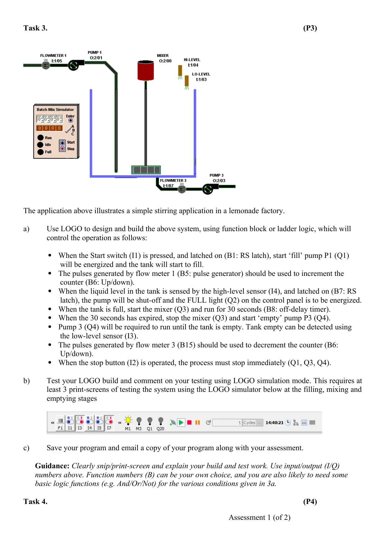
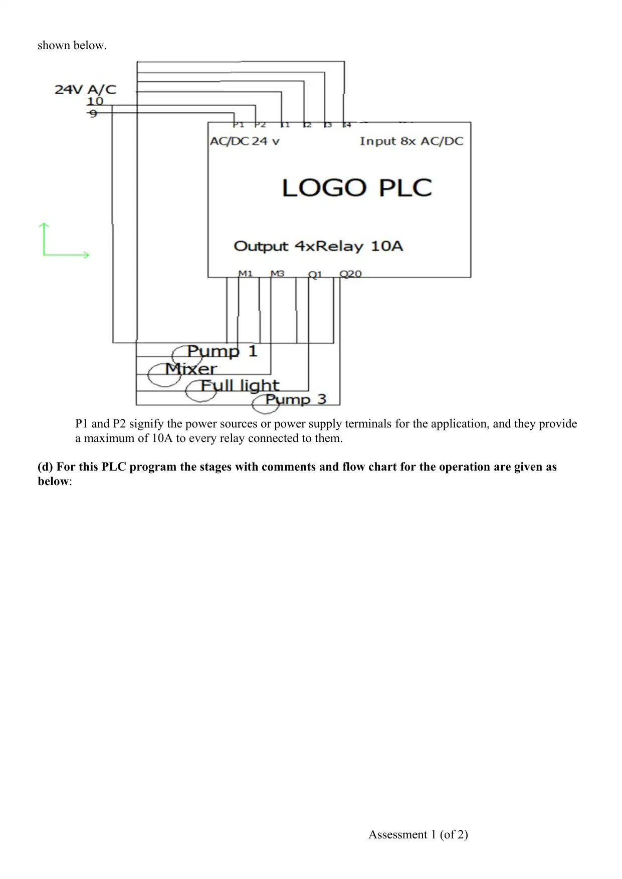
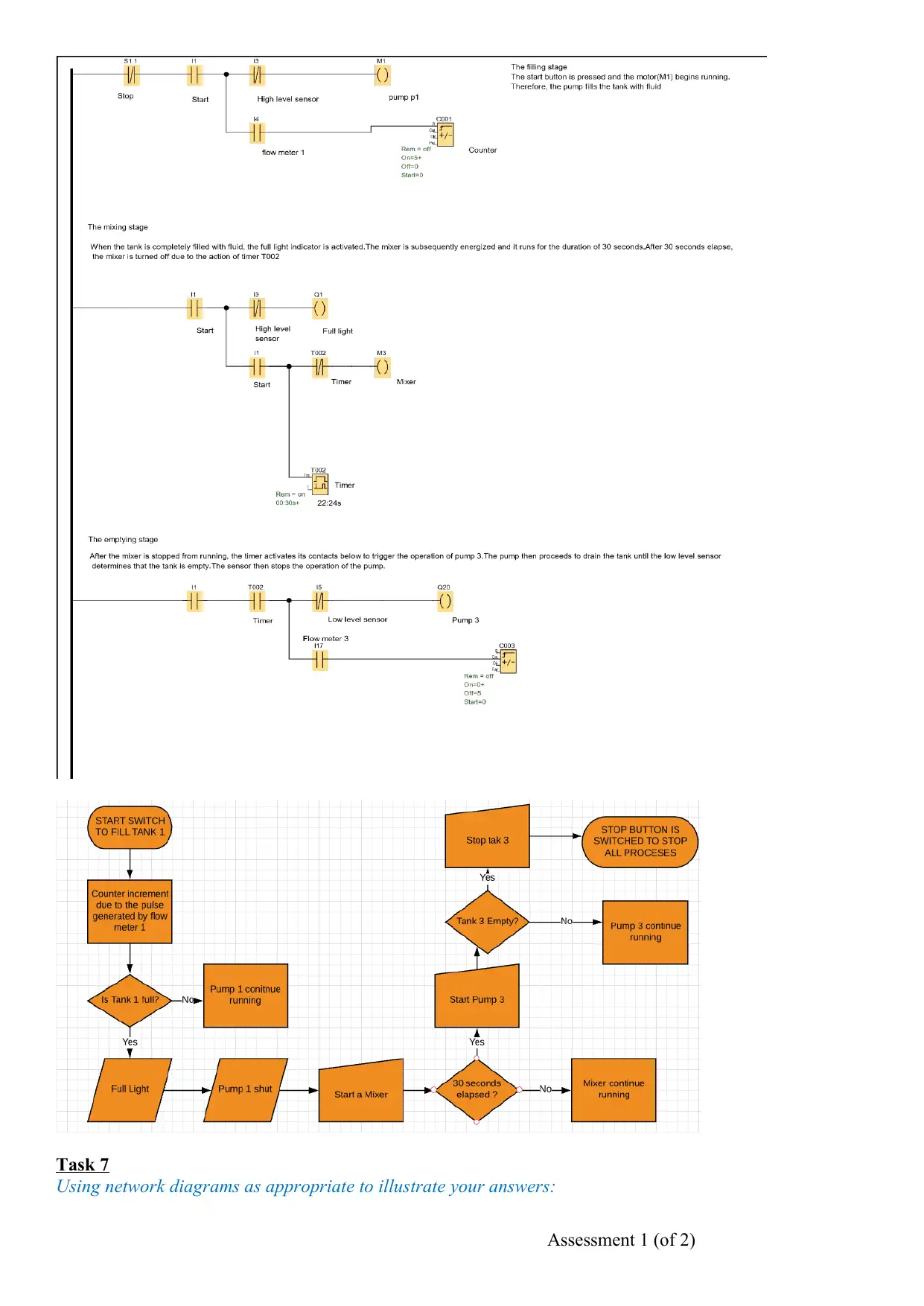
This document presents a student's response to a BTEC Level 3 Engineering assignment focused on Programmable Logic Controllers (PLCs). The assignment covers various aspects of PLCs, including the selection criteria and applications of unitary, modular, and rack-mounted controllers, along with their specific requirements. It explores the architecture of modern PLC systems, encompassing hardware, software, input/output interfaces, and communication links. The assignment requires the design and implementation of a control system using LOGO, including the development of program documentation such as I/O listings, wiring diagrams, and flow charts. Furthermore, it addresses health and safety considerations when working with PLCs, and the selection of communication media such as twisted pair, coaxial, and fiber optic cables. The document also examines network configurations like DeviceNet and Profibus, along with their protocols and communication standards, providing diagrams to illustrate the concepts. The assignment includes practical elements, such as the creation of a PLC program for a lemonade factory stirring application, including testing and simulation results.
Contribute Materials
Your contribution can guide someone’s learning journey. Share your
documents today.

Centre No: 04943
Technical Education Centre for Online Learning
Assignment Brief - Retake
Programme
Title:
BTEC Level 3 Award/Cert/Dip in
Engineering
Programme No: L3E-
Unit Number
and Title:
Unit 12: Selection & Application of
Programmable Logic Controllers
Edexcel Unit Code: D/600/0276
Coursework
Title: Selection & Programming Coursework
Number:
U12AR
Date issued 7/8/19 Duration / Deadline 1 week per task
Student Name Chris Retsis Assessor G Tweed
Tas
k
No
Assessment criteria covered Date Achieved Feedback
Retake?
Y/N
Attempt Comment
Attached?Grading criteria: P1, P2, P3,
1
P1: Describe the selection criteria and a practical
application for a unitary, a modular and a rack-mounted
programmable controller.
N
2 P2: Explain the system hardware and software
requirements for a programmable controller application. N
3
P3: Use a programmable technique to produce, store and
present a program that demonstrates the full range of
instruction types.
N
4
P4 explain the program documentation that has been used
for a complex engineering application Y
HOLD Yes
5
P5 describe the importance of health and safety when
working with programmable controlled equipment N
6
P6 explain how one example of each of the three types of
communication media would be selected for a specific
programmable controller application N
7 P7 describe a network and relevant standards and protocols
used for a modern programmable controller system. Y HOLD Yes
Scenario: You are starting out as an apprentice technician where you need to understand a range of
PLC programs. You have been asked to explain these and to use a PLC package such as LOGO to build
and test different types of analogue and digital circuits.
Evidence you must produce for this assignment: Written report with appropriate diagrams. Also a
copy of PLC files.
Sources of information:
Unit 12 course notes sections 1 - 4
Programmable Logic Controllers 4th Edition (W Bolton)
PLC Siemens LOGO user manual
Retake Conditions: Only one for retake work will be allowed for each task marked with a ‘Y’ above.
Coursework
Internal Verifier :
Sign (WWatson) 17/11/18
Assessment 1 (of 2)
Secure Best Marks with AI Grader
Need help grading? Try our AI Grader for instant feedback on your assignments.

Assessment 1 (of 2)

Assessment Record Sheet
1. Learner to fill in on retake submission:
Task ref(s) Evidence submitted
(e.g. written report, calculation,
file name).
Task ref(s) Evidence submitted
(e.g. written report, calculation, file
name).
4,7 Written report. pictures.
diagrams
Additional learner comments to the assessor:
Learner Declaration on Submission
I certify that the evidence submitted for this
assignment is my own. I have clearly referenced
any sources used in the work. I understand that
false declaration is a form of malpractice.
Learner Signature. Date.
18/08/19
2. Assessor to fill in on retake submission:
Task ref(s) Assessor comment on task(s) Task ref(s) Assessor comment on task(s)
4,7 HOLD
General feedback from the Assessor:
Decent attempt as per summarised comments above and detailed in the feedback below each task.
There is no official resubmission but will allow you to add some minor corrections to the end of this
document. Do not change any of the original work and return within 1 week to
electrical.team@tecol.co.uk
Has an extension to the deadline been approved by the Assessor due to extenuating
circumstances?
Assessor Declaration on Submission
I certify that the evidence submitted for this
assignment is the learner’s own. If it is not their
own work, then this is clearly explained and
detailed in the feedback and comments above
Assessor Signature. Date.
21/8/19
Sample Type:
(First or
resubmission)
Samples IV
Signature: Date:
Assessment 1 (of 2)

Assessment Tasks
Assessment grading instructions:
Tasks 1 to 3 are required for PASS (P) grade and must be attempted
Tasks 4 and 5 are also required for MERIT (M) grade (optional)
Work for Merit/Dist grades should also be supported by fully referenced evidence
Please carefully read your course guidance and add all your written work below the tasks. Remember to
sign (not typed) the learner section of assessment record sheet above
TECOL USES A PLAGIARISM CHECKER, SO IT IS IMPORTANT ALL ANSWERS MUST BE
YOUR OWN WORK
Tasks for Assessment 1
Task 1. (P1)
a. Identify an application for each type of PLC below
b. With the aid of block diagrams, provide details of their specific requirements and why you selected
the PLC for the application.
i. unitary,
ii. a modular
iii. a rack-mounted programmable controller
Guidance: a diagram and around 200 words for each
Task 2. (P2)
Explain, with the aid of diagrams and commercial examples, the architecture of a modern PLC system.
Include in your answer reference to:
a) system hardware,
b) two software options,
c) input / output interface including digital/analogue, range of voltage/current used,
d) field devices including examples popular devices
e) communication links including a commercial example.
Assessment 1 (of 2)
Secure Best Marks with AI Grader
Need help grading? Try our AI Grader for instant feedback on your assignments.

Task 3. (P3)
The application above illustrates a simple stirring application in a lemonade factory.
a) Use LOGO to design and build the above system, using function block or ladder logic, which will
control the operation as follows:
When the Start switch (I1) is pressed, and latched on (B1: RS latch), start ‘fill’ pump P1 (Q1)
will be energized and the tank will start to fill.
The pulses generated by flow meter 1 (B5: pulse generator) should be used to increment the
counter (B6: Up/down).
When the liquid level in the tank is sensed by the high-level sensor (I4), and latched on (B7: RS
latch), the pump will be shut-off and the FULL light (Q2) on the control panel is to be energized.
When the tank is full, start the mixer (Q3) and run for 30 seconds (B8: off-delay timer).
When the 30 seconds has expired, stop the mixer (Q3) and start ‘empty’ pump P3 (Q4).
Pump 3 (Q4) will be required to run until the tank is empty. Tank empty can be detected using
the low-level sensor (I3).
The pulses generated by flow meter 3 (B15) should be used to decrement the counter (B6:
Up/down).
When the stop button (I2) is operated, the process must stop immediately (Q1, Q3, Q4).
b) Test your LOGO build and comment on your testing using LOGO simulation mode. This requires at
least 3 print-screens of testing the system using the LOGO simulator below at the filling, mixing and
emptying stages
c) Save your program and email a copy of your program along with your assessment.
Guidance: Clearly snip/print-screen and explain your build and test work. Use input/output (I/Q)
numbers above. Function numbers (B) can be your own choice, and you are also likely to need some
basic logic functions (e.g. And/Or/Not) for the various conditions given in 3a.
Task 4. (P4)
Assessment 1 (of 2)

i) Using the program developed in T3, produce a documentation package that will enable the
application to be correctly installed and supported, include
a) An I/O listing clearly identifying the field devices
b) Input card wiring diagram to the field devices
c) Output card wiring diagram to the field devices
d) A flow chart of the program, with comments on key program stages/decisions
Task 5. (P5)
Considering PLC safety issues:
a) Describe the importance of health and safety when working with programmable controlled
equipment.
b) Describe the method for connecting a normal start / stop buttons and an emergency stop button
for use in potentially dangerous machinery. Explain the important differences between the two
connection methods.
c) Make a sketch of a common hard wired emergency stop system for a system that includes a
programmable controller.
d) In the event of and programmable control system not running correctly, give a list of four actions
with reasons that you would take to remedy the situation.
Guidance: (400 words and appropriate diagrams)
Task 6. (P6)
Communication media is used to connect distributed components of a PLC system. Write an
illustrated description of each of the following communications media, including the advantages and
disadvantages for each type of media and one possible application for each:
a. Twisted pair
b. Coaxial
c. Fibre optic
Guidance: Provide reasons for your selecting your applications. Illustrations should be referenced
extracts from commercial specifications for each cable type (400 words)
Assessment 1 (of 2)

Task 7. (P7)
Using network diagrams as appropriate to illustrate your answers:
a. Explain the terms “Bus” as applied to a modern programmable controller system.
b. Describe, with the aid of diagrams, a Devicenet or Profibus network configuration that could be
using to connect a programmable controller system.
c. For the Bus network configuration in T7b, describe the protocols and communication standards
used.
Guidance: (400 words and appropriate diagrams)
Assessment 1 (of 2)
Paraphrase This Document
Need a fresh take? Get an instant paraphrase of this document with our AI Paraphraser

Task4
Using the program developed in T3, produce a documentation package that will enable the application to be
correctly installed and supported, include
a) An I/O listing clearly identifying the field devices
b) Input card wiring diagram to the field devices
c) Output card wiring diagram to the field devices
d) A flow chart of the program, with comments on key program stages/decisions
(a)This part contains the parameters of the inputs and outputs which were used in the programming of the
PLC of U12A1.
Inputs of the PLC program developed:
Start (1). This is a button that is pressed to start the operation of the whole PLC system.
Stop (4). When the system is to be stopped the stop button is pressed and the whole operation is
brought to a halt
High-level sensor (3). This is an input that will check the level of water in the Tanks which are being
filled. It checks the high level.
Low-level sensor (2). This is an input that will check the level of water in the Tanks which are being
filled. It checks the low level.
Outputs of the PLC program developed:
Pump P1. Pump 1 will start operating immediately the start button is pressed.
Full Light Q1. And after the Tank 1 which is being filled using the pump 1 is full the full light will
indicate that it is full.
Mixer M3. And immediately the Full light comes (indication that tank 1 is full). The mixer M3 will
start and operates for 30 seconds.
Pump 3 Q 20. After the elapse of 30 second, Pump 3 will start operating.
(b) The input card illustration to the field devices.
The input card illustration showing how the input devices are linked to the input terminals of the PLC
controller is shown below.
It illustrates how the four input switches are connected to the PLC device at the input terminals.
Assessment 1 (of 2)

(c) The output card illustration to the field devices is as shown below.
It illustrates how the output field mechanisms are connected to the output terminals of the PLC system, via
the output terminals. To clearly understand the entire wiring of the whole application, the wiring diagram
that illustrates the interaction between the input filed devices, the PLC and the output field devices is as
Assessment 1 (of 2)

shown below.
P1 and P2 signify the power sources or power supply terminals for the application, and they provide
a maximum of 10A to every relay connected to them.
(d) For this PLC program the stages with comments and flow chart for the operation are given as
below:
Assessment 1 (of 2)
P1 and P2 signify the power sources or power supply terminals for the application, and they provide
a maximum of 10A to every relay connected to them.
(d) For this PLC program the stages with comments and flow chart for the operation are given as
below:
Assessment 1 (of 2)
Secure Best Marks with AI Grader
Need help grading? Try our AI Grader for instant feedback on your assignments.

Task 7
Using network diagrams as appropriate to illustrate your answers:
Assessment 1 (of 2)
Using network diagrams as appropriate to illustrate your answers:
Assessment 1 (of 2)

a. Explain the terms “Bus” as applied to a modern programmable controller system.
b. Describe, with the aid of diagrams, a Devicenet or Profibus network configuration that could be
using to connect a programmable controller system.
c. For the Bus network configuration in T7b, describe the protocols and communication standards
used.
(a).. BUS in PLC
In PLC, BUS is a communication power line protocol for the communication between the PLC devices. It
employed for the power line wiring for the control and signal in communication. The diagram below
illustrates the BUS in PLC. There are some types of BUS which include:
Address bus
Control Bus
Data Bus
I/O system Bus
Figure 1: Showing Bus topology.
(b) According to Lincoln (2011), the DeviceNet network is an industrial protocol that consists of several
application layers.64 nodes consisting of either a programmable logic controller (PLC), a useful instrument
or basic sensors can be interlinked in this network. Moreover, the DeviceNet protocol adheres to the
Controller Area Network (CAN) format to permit the numerous devices in the network to share data.
Furthermore, the DeviceNet protocol usually applies a trunk line-dropline framework, whereby minor lines
link with the machines before they are linked to the main artery of the network. However, the minor lines
should not have a length that exceeds six meters.
Assessment 1 (of 2)

The DeviceNet cable provides power to numerous devices according to their specific energy
demands. Furthermore, Lincoln (2011), adds that the protocol permits various data transmission formats
including the cyclic, strobed and polled format. The network can also be constructed in either the Master-
slave or multiple master modes. The network baud rate is dependent on the length of the primary line;
therefore, one should consider this fact will connect the different end to endpoints. Accordingly, 100 meters
of the cable has a baud rate of 500 Kbps, 250 meters has a rate of 250Kbps and 500 meters will have a baud
rate of 125kbps. Moreover, Namie (2015) explains that the upper layers of DeviceNet are structured per the
common industrial protocol. This implies that it adheres to the open systems interconnection (OSI)model
that comprises of seven layers including the physical level, data link level, network layer, transport level,
session layer, presentation and application layers.
Assessment 1 (of 2)
Paraphrase This Document
Need a fresh take? Get an instant paraphrase of this document with our AI Paraphraser

(c) The DeviceNet network can only supply 24V DC voltage and 8 Amperes, and therefore it can only
operate low-energy equipment. In case a device that consumes a higher level of energy has to be in
cooperated into the system, then an extra power source is necessary. Moreover, Namie (2015) asserts that
the length of the network depends on the type of cable being used and how fast data has to be transmitted.
Additionally, to configure the network properly, one has to consider EDS files of the equipment in the
network.
The EDS is the abbreviation for the electronic datasheet and it contains the relevant standards that govern
the operation of each device. Before adding a device to the network, it is important to carefully consider the
recommendations in the electronic datasheet, to set various parameters in the most effective manner.
According to Razak (2013), most device vendors provide such specifications that make it easier to connect
their applications to a DeviceNet network. Moreover, the electronic datasheet file has to be obtained from
the website of the vendor, prior to being uploaded to the necessary software that configures the DeviceNet
system.
The operation of the devicenet system is based on controller area network abbreviated, CAN, for task
automation through data transmission to various devices. It offers for a main line having separate buses for
signal and power. Devicenet system defines baud rates of 500, 250 and 125 kbps. The length of the capable
that transmit data in this system is inversely proportional to the speed. The entire devicenet system is
capable of supporting 64 nodes in a single logical network. It as well support master-slave and also peer to
peer communication, however, devices are commonly operated in master-slave model. Devicenet also
support 4 different types of messages to and fro slave components which include: clocked, cyclic, status
change or cod, and requested. A connection is first led through unconnected message manager or else in
group 2 unconnected ports. After that explicit as well as implicit messages can be sent to a device. Actually,
explicit messages are referred as packets of data expecting answer from another device. Explicit messages
are data sets with no limit of time. Contrary to that, implicit messages are said to be time sensitive thus
communicated in real time over the network. It is worth noting prior initiation of implicit communication, a
connection for explicit message must exist. On establishment of a connection, the control area network
identification is applied in sending data to the corresponding network nodes.
Assessment 1 (of 2)

References
Bolton, W. (2012). Programmable Logic Controllers. 4th ed. London: Elsevier, p.5.
Heafner, J. (2014). An IEEE 802.4 token bus network simulation. 5th ed. Gaithersburg, MD: U.S. Dept. of
Commerce, National Bureau of Standards, p.12.
Lincoln, M. (2011). DeviceNet control system compared. Assembly Automation, 19(4), p.18.
Namie, M. (2015). Application of PLC for PA and Future Evolution of PLC-based Process
Controller. JAPAN TAPPI JOURNAL, 60(3), pp.341-347.
Razak, I. (2013). DeviceNet Messaging Protocol. Biomedical Safety & Standards, 43(10), p.80.
Wagner, F. (2013). PLC. 10th ed. Richland, Wash.: Hanford Site (Wash.), p.9.
Assessment 1 (of 2)
1 out of 15
Related Documents

Your All-in-One AI-Powered Toolkit for Academic Success.
+13062052269
info@desklib.com
Available 24*7 on WhatsApp / Email
Unlock your academic potential
© 2024 | Zucol Services PVT LTD | All rights reserved.