BTEC Mechanical Engineering: Thermodynamic Systems Assignment
VerifiedAdded on 2022/11/03
|13
|2664
|277
Homework Assignment
AI Summary
This document provides a comprehensive solution to a thermodynamic systems assignment, addressing key concepts in mechanical engineering. The assignment delves into calculating heat energy requirements for phase changes, analyzing the process of refrigeration within heat exchangers, and exploring the effects of refrigerant phase changes on heat transfer. Furthermore, it includes detailed calculations for thermal strain in a steel tube, applying Charles' Law to determine gas volume changes, and solving problems related to gas properties using the combined gas law and characteristic gas equation. The solution culminates in determining the thermal efficiency of a heat exchanger, demonstrating a thorough understanding of thermodynamic principles and their practical applications in engineering systems.

Thermodynamic Systems 1
THERMODYNAMIC SYSTEMS
Name
Course
Professor
University
City/state
Date
THERMODYNAMIC SYSTEMS
Name
Course
Professor
University
City/state
Date
Paraphrase This Document
Need a fresh take? Get an instant paraphrase of this document with our AI Paraphraser
Thermodynamic Systems 2
Thermodynamic Systems
Introduction
This assignment involves solving various problems related to thermodynamic systems and
determining the effect of energy transfer on these systems. The assignment helps in analyzing
data, choosing and applying scientific and mathematical principles related to heat transfer and
how it affects various engineering systems.
Tasks
Task 1
a) Heat energy required
The total heat is the amount of heat required is that needed to convert the 10kg of ice from solid
at -30°C to solid at 0°C and the heat needed to convert the ice from solid at 0°C to liquid (water)
at 0° . The formula for heat needed is:
Heat, Q = (m x cp x ∆T) + (m x cf)
Where Q = total heat, m = mass of ice, cp = specific heat capacity of ice, ∆T = change in
temperature, and cf = specific latent heat of fusion of ice.
Therefore
Q = (10kg x 2.1 kJ/kg°C x 30°C) + (10kg x 335 kJ/kg)
= 630 KJ + 3,350 KJ
= 3,980 KJ
= 3.98 MJ
Thermodynamic Systems 3
b) Process of refrigeration
i) The process of refrigeration as a heat exchanger
Introduction
Heat exchangers play a very crucial role in refrigeration systems. The fundamental
function of a heat exchanger is to exchange or transfer heat from one fluid to another.
Refrigeration basically involves removal of heat from a system and disposing it from the system.
This process relies on the principle of convection. The process of refrigeration in a heat
exchanger takes place by use of a compressor and refrigerant gases. A refrigerant is a stable gas
with the capacity to compress and expand, which makes it able to absorb and discharge heat.
How refrigeration works
A refrigeration system comprises of five main components. These components are: a
compressor fluid refrigerant, condenser coils, evaporator and an expansion device. The
compressor works by constricting the refrigerant vapor, which increases its pressure and
transfers it to the coils located outside the refrigeration system. The mixture of the cooler air
temperature and the hot gas present in the coils produces a liquid. This liquid is at high pressure
and this condition makes the refrigerant to cool down while flowing into the coils located inside
the refrigeration system. The refrigerant is able to absorb any heat present in the refrigeration
system thus cooling down all the air found in it. Thereafter, the refrigerant is able to evaporate
and become a gas, and flows back to the compressor for the refrigeration cycle to start over
again. This process is continuous and the refrigeration system uses a heat exchanger as an
evaporator.
⊘ This is a preview!⊘
Do you want full access?
Subscribe today to unlock all pages.
Trusted by 1+ million students worldwide
Thermodynamic Systems 4
In other words, refrigeration cycle comprises of two main pressures: low side (low
pressure or evaporating side) and high side (high pressure or condensing side). These two
pressure sides are separated by the compressor and metering device. The metering device is used
to control flow of refrigerant whereas the compressor is used to compress the vapor.
How heat exchangers work
A heat exchanger refers to a device that is used to transfer thermal or heat energy
between different mediums. Heat exchangers are used in heating, ventilation and air conditioning
(HVAC) systems and also help engines and machines to work efficiently. Some of the basic
examples of heat exchangers are: evaporators, condensers and earth coils. The main focus of this
report is on how a heat exchanger is used in a refrigeration system, such as a HVAC system. The
fundamental function of a HVAC system is to remove heat from inside a building and transfer it
outside. This process largely depends on a substance known as a refrigerant. During refrigeration
process, the refrigerant works by carrying, absorbing and releasing heat while it changes state
from gaseous state to liquid state.
The refrigeration process begins with the refrigerant moving through different
components of the refrigeration system, and transferring heat as it moves. The refrigerant starts
moving from the evaporator coils as a low-pressure liquid. If it is a building, the fan inside the
building blows warm air across the coils. The refrigerant is able to absorb heat from the warm
air, which turns it from liquid to vapor. After absorbing the warm air, the refrigerant now
becomes a low-pressure warm gas and starts moving into the compressor. The compressor is
usually positioned outdoors. Inside the compressor, the refrigerant gets converted into a high-
pressure, warm gas. This high-pressure, warm gas them moves into the condenser that is also
usually located outdoors. As air moves over the condenser, it is able to absorb heat from the
Paraphrase This Document
Need a fresh take? Get an instant paraphrase of this document with our AI Paraphraser
Thermodynamic Systems 5
refrigerant, causing it to get converted back into a high-pressure, cool liquid. This refrigerant
then moves into the expansion valve where it cools off more before moving back to the
evaporator where it absorbs extra heat to transfer it to the building or machine/engine (Nguyen,
2018).
There are different types of heat exchangers. Some of these include: chillers, shell and
tube heat exchanger, heat pumps, plate heat exchanger, furnace heater, chilled beam heat
exchanger, heat pipe, water boiler, rotary wheel heat exchanger, water heating element, radiators,
furnace evaporator coil, micro-channel heat exchangers, duct electric heater, trench heater, duct
plate heat exchanger, and finned tube coil, among others (Evans, 2018).
How phase change of the refrigerant affects heat transfer
During refrigeration cycle, the refrigerant undergoes phase change by hanging from
liquid to vapor or from vapor to liquid (Khan, 2016). This phase change depends on the stage of
the refrigeration cycle or where the refrigerant is at that particular time – whether at a low-
pressure side or high-pressure side. This phase change enables the refrigerant to either
absorb/store or release a substantial quantity of heat or thermal energy. There are also several
factors that affect phase change of refrigerant such as thickness of the refrigerant, temperature,
and position of the refrigerant.
In general, phase change is very essential in refrigeration process. This is because phase
change enables the refrigerant to either absorb or release heat. The phase change is facilitated by
the expansion valve and compressor. These two components changes the pressure, which is
essential in creating suitable conditions for the refrigerant to either turn into a liquid or gas. The
compressor increases pressure whereas the expansion valve reduces pressure. When pressure is
Thermodynamic Systems 6
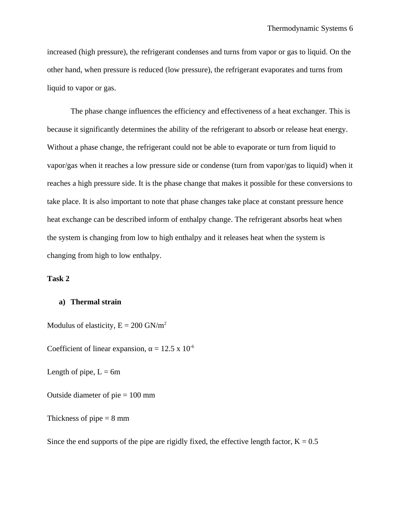
increased (high pressure), the refrigerant condenses and turns from vapor or gas to liquid. On the
other hand, when pressure is reduced (low pressure), the refrigerant evaporates and turns from
liquid to vapor or gas.
The phase change influences the efficiency and effectiveness of a heat exchanger. This is
because it significantly determines the ability of the refrigerant to absorb or release heat energy.
Without a phase change, the refrigerant could not be able to evaporate or turn from liquid to
vapor/gas when it reaches a low pressure side or condense (turn from vapor/gas to liquid) when it
reaches a high pressure side. It is the phase change that makes it possible for these conversions to
take place. It is also important to note that phase changes take place at constant pressure hence
heat exchange can be described inform of enthalpy change. The refrigerant absorbs heat when
the system is changing from low to high enthalpy and it releases heat when the system is
changing from high to low enthalpy.
Task 2
a) Thermal strain
Modulus of elasticity, E = 200 GN/m2
Coefficient of linear expansion, α = 12.5 x 10⁻⁶
Length of pipe, L = 6m
Outside diameter of pie = 100 mm
Thickness of pipe = 8 mm
Since the end supports of the pipe are rigidly fixed, the effective length factor, K = 0.5
⊘ This is a preview!⊘
Do you want full access?
Subscribe today to unlock all pages.
Trusted by 1+ million students worldwide
Thermodynamic Systems 7
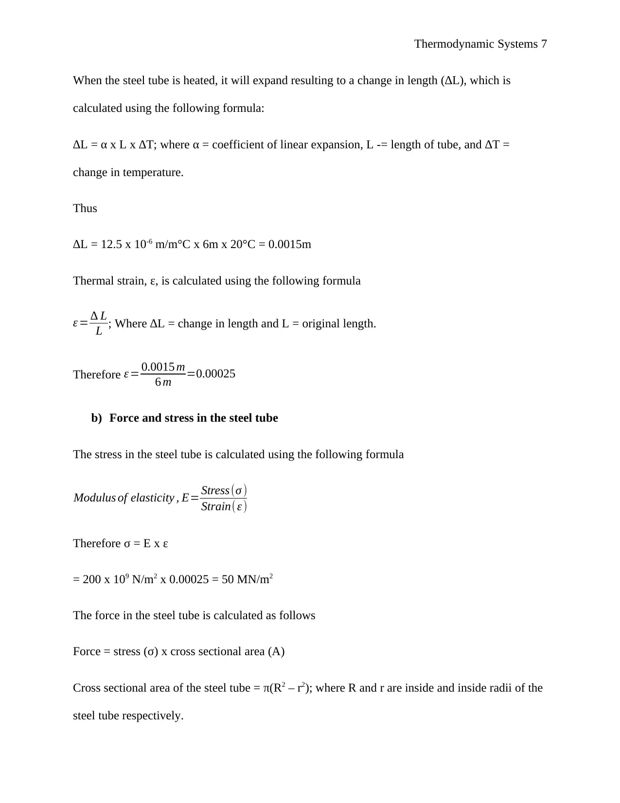
When the steel tube is heated, it will expand resulting to a change in length (∆L), which is
calculated using the following formula:
∆L = α x L x ∆T; where α = coefficient of linear expansion, L -= length of tube, and ∆T =
change in temperature.
Thus
∆L = 12.5 x 10⁻⁶ m/m°C x 6m x 20°C = 0.0015m
Thermal strain, ε, is calculated using the following formula
ε = ∆ L
L ; Where ∆L = change in length and L = original length.
Therefore ε = 0.0015 m
6 m =0.00025
b) Force and stress in the steel tube
The stress in the steel tube is calculated using the following formula
Modulus of elasticity , E= Stress (σ )
Strain(ε )
Therefore σ = E x ε
= 200 x 109 N/m2 x 0.00025 = 50 MN/m2
The force in the steel tube is calculated as follows
Force = stress (σ) x cross sectional area (A)
Cross sectional area of the steel tube = π(R2 – r2); where R and r are inside and inside radii of the
steel tube respectively.
Paraphrase This Document
Need a fresh take? Get an instant paraphrase of this document with our AI Paraphraser
Thermodynamic Systems 8
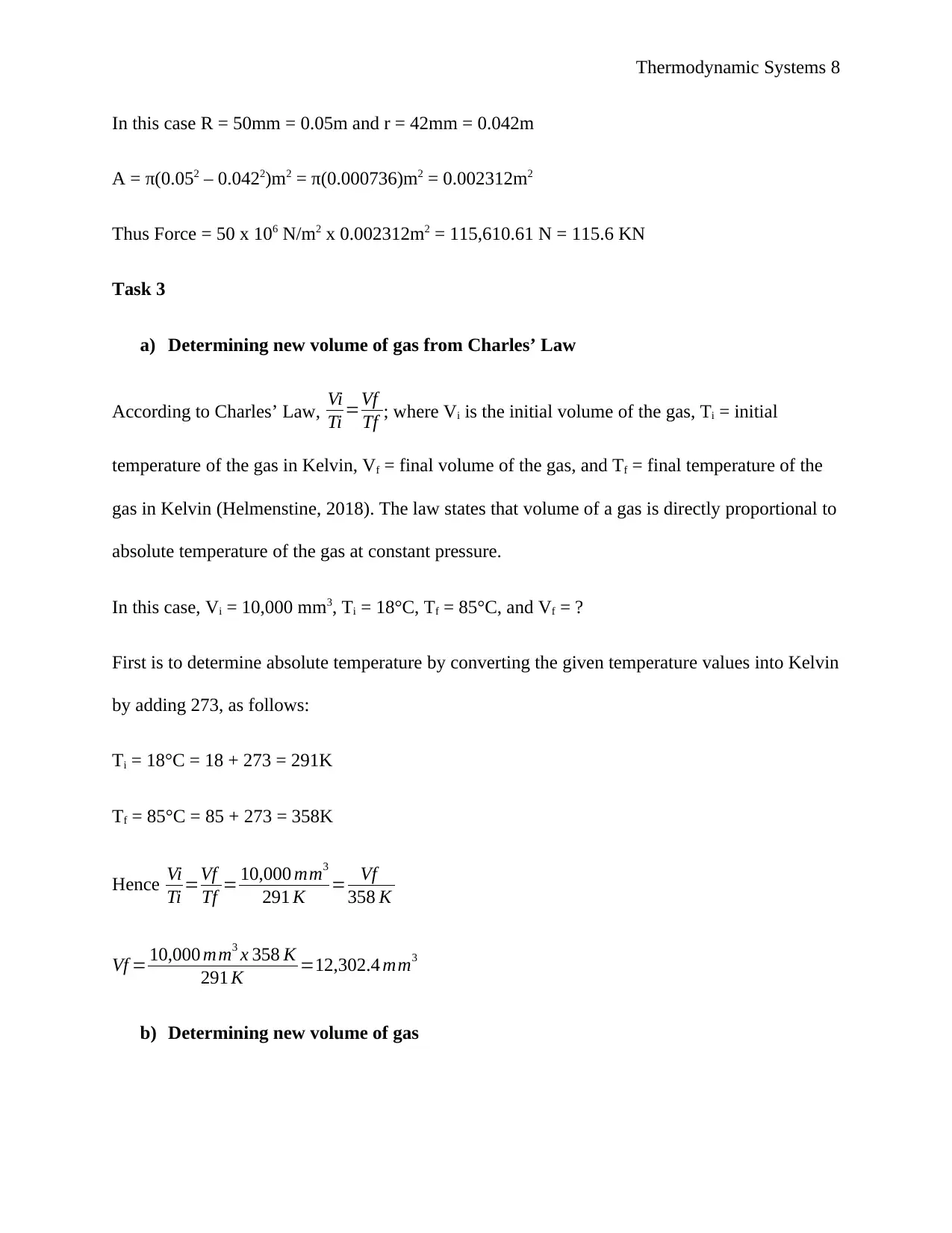
In this case R = 50mm = 0.05m and r = 42mm = 0.042m
A = π(0.052 – 0.0422)m2 = π(0.000736)m2 = 0.002312m2
Thus Force = 50 x 106 N/m2 x 0.002312m2 = 115,610.61 N = 115.6 KN
Task 3
a) Determining new volume of gas from Charles’ Law
According to Charles’ Law, Vi
Ti =Vf
Tf ; where Vi is the initial volume of the gas, Ti = initial
temperature of the gas in Kelvin, Vf = final volume of the gas, and Tf = final temperature of the
gas in Kelvin (Helmenstine, 2018). The law states that volume of a gas is directly proportional to
absolute temperature of the gas at constant pressure.
In this case, Vi = 10,000 mm3, Ti = 18°C, Tf = 85°C, and Vf = ?
First is to determine absolute temperature by converting the given temperature values into Kelvin
by adding 273, as follows:
Ti = 18°C = 18 + 273 = 291K
Tf = 85°C = 85 + 273 = 358K
Hence Vi
Ti =Vf
Tf = 10,000 mm3
291 K = Vf
358 K
Vf = 10,000 mm3 x 358 K
291 K =12,302.4 mm3
b) Determining new volume of gas
Thermodynamic Systems 9
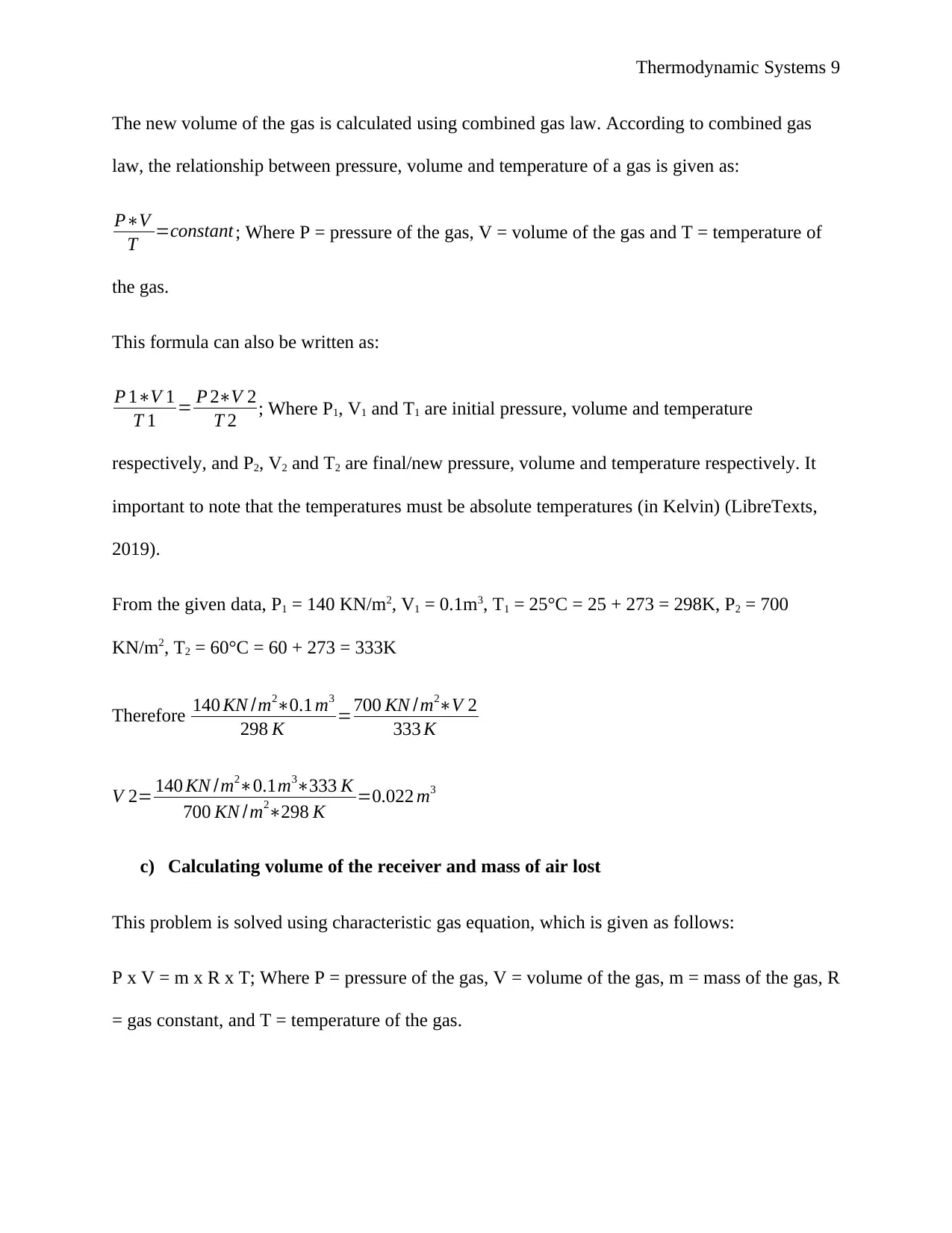
The new volume of the gas is calculated using combined gas law. According to combined gas
law, the relationship between pressure, volume and temperature of a gas is given as:
P∗V
T =constant ; Where P = pressure of the gas, V = volume of the gas and T = temperature of
the gas.
This formula can also be written as:
P 1∗V 1
T 1 = P 2∗V 2
T 2 ; Where P1, V1 and T1 are initial pressure, volume and temperature
respectively, and P2, V2 and T2 are final/new pressure, volume and temperature respectively. It
important to note that the temperatures must be absolute temperatures (in Kelvin) (LibreTexts,
2019).
From the given data, P1 = 140 KN/m2, V1 = 0.1m3, T1 = 25°C = 25 + 273 = 298K, P2 = 700
KN/m2, T2 = 60°C = 60 + 273 = 333K
Therefore 140 KN /m2∗0.1 m3
298 K =700 KN /m2∗V 2
333 K
V 2= 140 KN /m2∗0.1m3∗333 K
700 KN /m2∗298 K =0.022 m3
c) Calculating volume of the receiver and mass of air lost
This problem is solved using characteristic gas equation, which is given as follows:
P x V = m x R x T; Where P = pressure of the gas, V = volume of the gas, m = mass of the gas, R
= gas constant, and T = temperature of the gas.
⊘ This is a preview!⊘
Do you want full access?
Subscribe today to unlock all pages.
Trusted by 1+ million students worldwide
Thermodynamic Systems 10
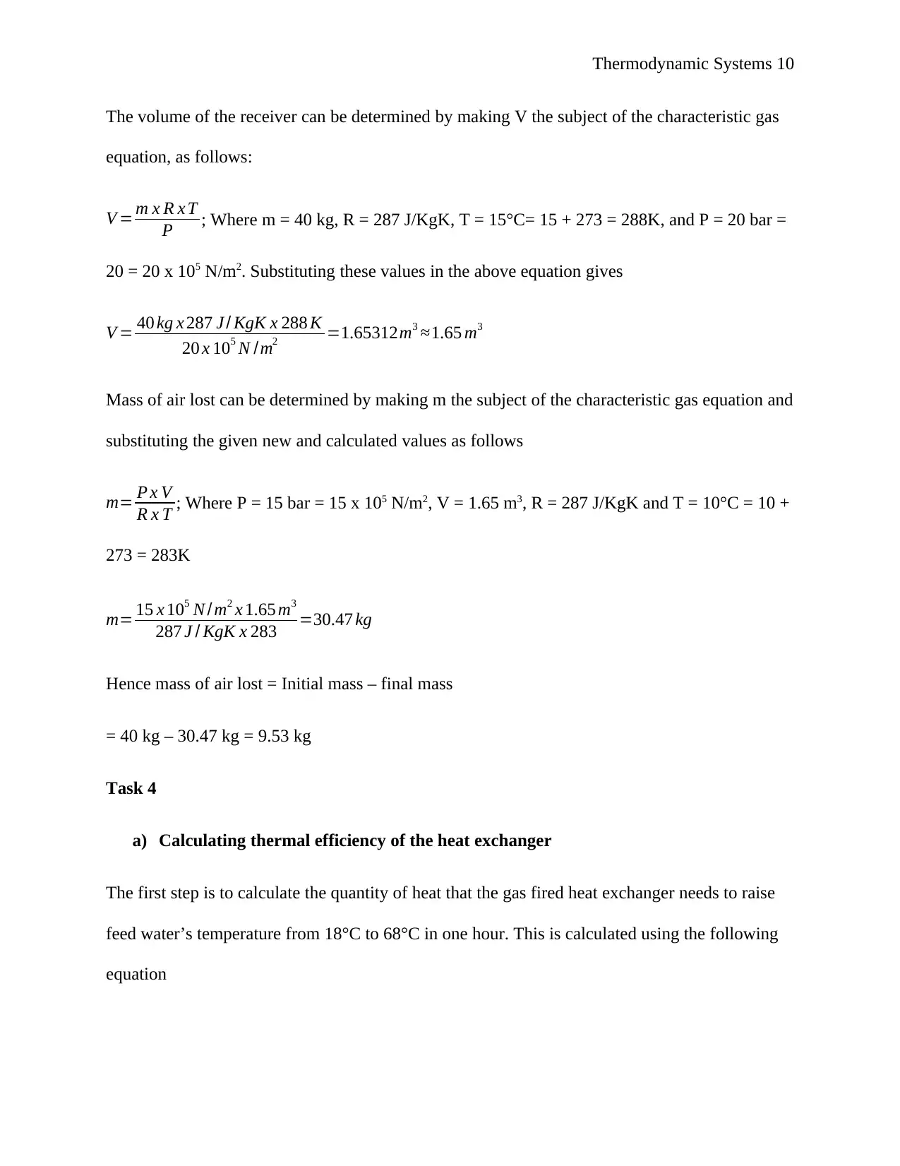
The volume of the receiver can be determined by making V the subject of the characteristic gas
equation, as follows:
V = m x R x T
P ; Where m = 40 kg, R = 287 J/KgK, T = 15°C= 15 + 273 = 288K, and P = 20 bar =
20 = 20 x 105 N/m2. Substituting these values in the above equation gives
V = 40 kg x 287 J / KgK x 288 K
20 x 105 N /m2 =1.65312m3 ≈1.65 m3
Mass of air lost can be determined by making m the subject of the characteristic gas equation and
substituting the given new and calculated values as follows
m= P x V
R x T ; Where P = 15 bar = 15 x 105 N/m2, V = 1.65 m3, R = 287 J/KgK and T = 10°C = 10 +
273 = 283K
m= 15 x 105 N / m2 x 1.65 m3
287 J / KgK x 283 =30.47 kg
Hence mass of air lost = Initial mass – final mass
= 40 kg – 30.47 kg = 9.53 kg
Task 4
a) Calculating thermal efficiency of the heat exchanger
The first step is to calculate the quantity of heat that the gas fired heat exchanger needs to raise
feed water’s temperature from 18°C to 68°C in one hour. This is calculated using the following
equation
Paraphrase This Document
Need a fresh take? Get an instant paraphrase of this document with our AI Paraphraser
Thermodynamic Systems 11
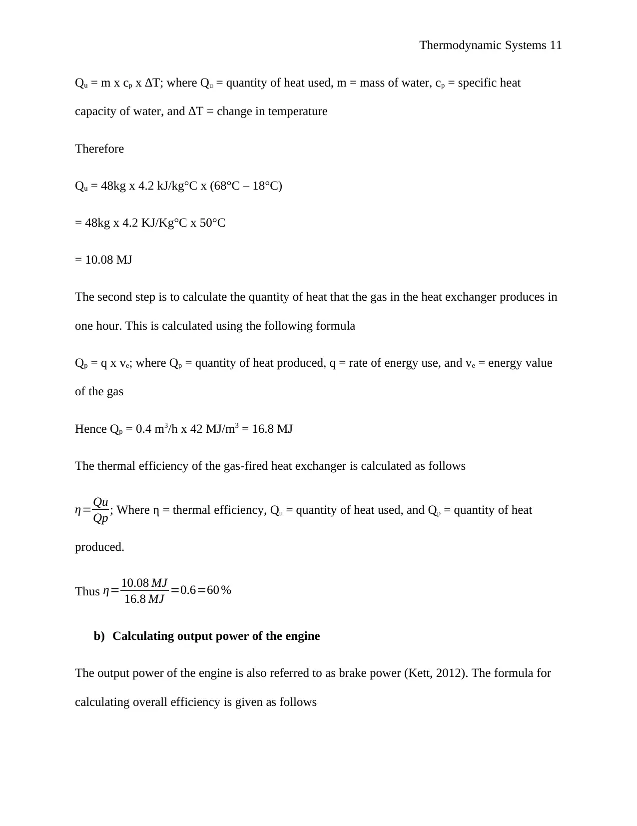
Qu = m x cp x ∆T; where Qu = quantity of heat used, m = mass of water, cp = specific heat
capacity of water, and ∆T = change in temperature
Therefore
Qu = 48kg x 4.2 kJ/kg°C x (68°C – 18°C)
= 48kg x 4.2 KJ/Kg°C x 50°C
= 10.08 MJ
The second step is to calculate the quantity of heat that the gas in the heat exchanger produces in
one hour. This is calculated using the following formula
Qp = q x ve; where Qp = quantity of heat produced, q = rate of energy use, and ve = energy value
of the gas
Hence Qp = 0.4 m3/h x 42 MJ/m3 = 16.8 MJ
The thermal efficiency of the gas-fired heat exchanger is calculated as follows
η=Qu
Qp ; Where η = thermal efficiency, Qu = quantity of heat used, and Qp = quantity of heat
produced.
Thus η=10.08 MJ
16.8 MJ =0.6=60 %
b) Calculating output power of the engine
The output power of the engine is also referred to as brake power (Kett, 2012). The formula for
calculating overall efficiency is given as follows
Thermodynamic Systems 12
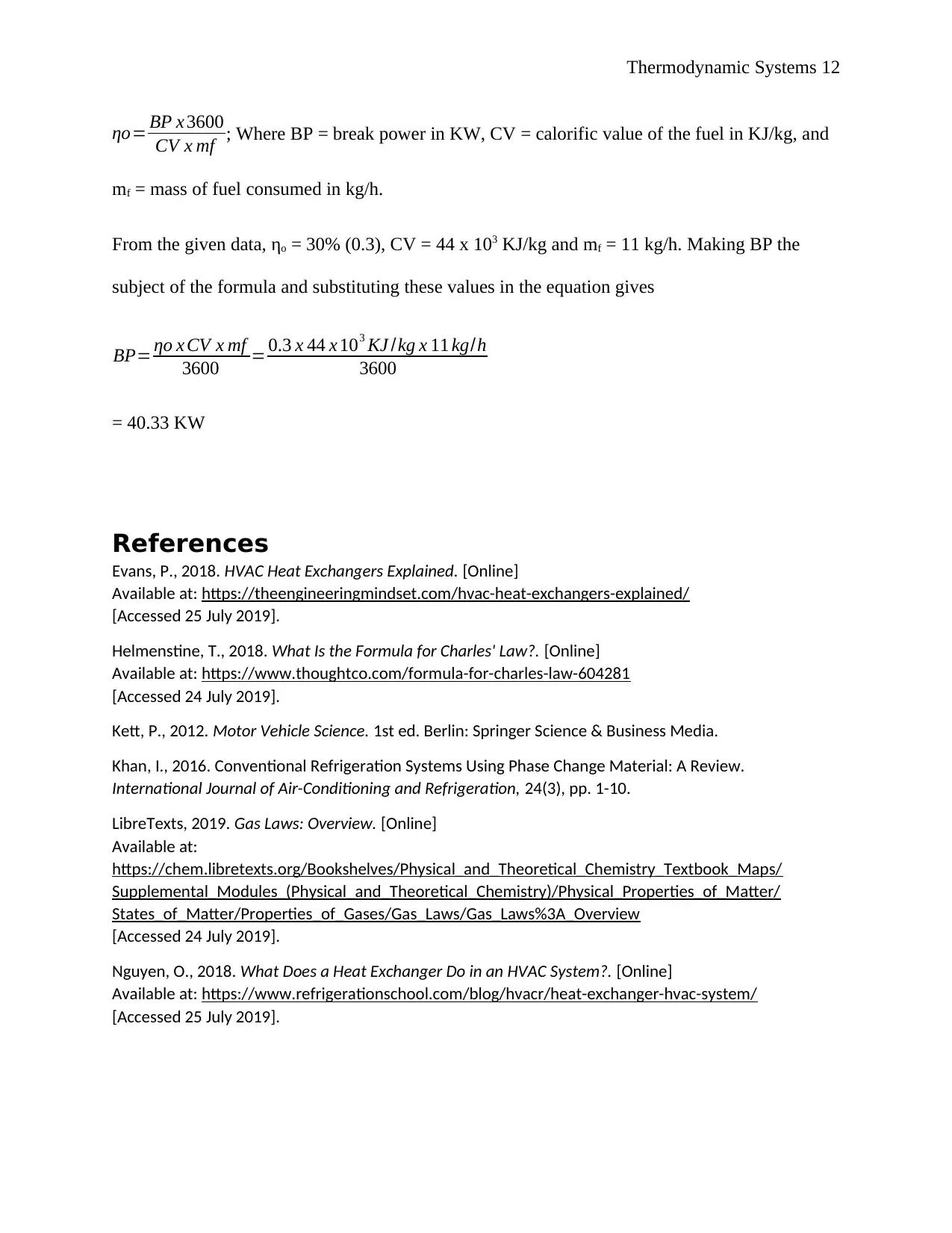
ηo= BP x 3600
CV x mf ; Where BP = break power in KW, CV = calorific value of the fuel in KJ/kg, and
mf = mass of fuel consumed in kg/h.
From the given data, ηo = 30% (0.3), CV = 44 x 103 KJ/kg and mf = 11 kg/h. Making BP the
subject of the formula and substituting these values in the equation gives
BP= ηo x CV x mf
3600 = 0.3 x 44 x 103 KJ /kg x 11 kg/h
3600
= 40.33 KW
References
Evans, P., 2018. HVAC Heat Exchangers Explained. [Online]
Available at: https://theengineeringmindset.com/hvac-heat-exchangers-explained/
[Accessed 25 July 2019].
Helmenstine, T., 2018. What Is the Formula for Charles' Law?. [Online]
Available at: https://www.thoughtco.com/formula-for-charles-law-604281
[Accessed 24 July 2019].
Kett, P., 2012. Motor Vehicle Science. 1st ed. Berlin: Springer Science & Business Media.
Khan, I., 2016. Conventional Refrigeration Systems Using Phase Change Material: A Review.
International Journal of Air-Conditioning and Refrigeration, 24(3), pp. 1-10.
LibreTexts, 2019. Gas Laws: Overview. [Online]
Available at:
https://chem.libretexts.org/Bookshelves/Physical_and_Theoretical_Chemistry_Textbook_Maps/
Supplemental_Modules_(Physical_and_Theoretical_Chemistry)/Physical_Properties_of_Matter/
States_of_Matter/Properties_of_Gases/Gas_Laws/Gas_Laws%3A_Overview
[Accessed 24 July 2019].
Nguyen, O., 2018. What Does a Heat Exchanger Do in an HVAC System?. [Online]
Available at: https://www.refrigerationschool.com/blog/hvacr/heat-exchanger-hvac-system/
[Accessed 25 July 2019].
⊘ This is a preview!⊘
Do you want full access?
Subscribe today to unlock all pages.
Trusted by 1+ million students worldwide
1 out of 13
Related Documents


Your All-in-One AI-Powered Toolkit for Academic Success.
+13062052269
info@desklib.com
Available 24*7 on WhatsApp / Email
![[object Object]](/_next/static/media/star-bottom.7253800d.svg)
Unlock your academic potential
Copyright © 2020–2026 A2Z Services. All Rights Reserved. Developed and managed by ZUCOL.