CPCCBC4010B Assessment 6: Building Demolition and Construction Plan
VerifiedAdded on 2021/06/17
|40
|6766
|220
Report
AI Summary
This report outlines a comprehensive plan for the demolition of a building, addressing legislative and planning requirements, and emphasizing safe work practices, particularly when dealing with asbestos-containing materials. It details a step-by-step approach, including risk management, demolition work plans, and hazard control measures. The report also covers structural load assessments, illustrating load paths and the application of wind, dead, and live loads. Furthermore, it researches and lists the Building Code of Australia requirements for various zones, including bushfire (medium risk), high wind, and earthquake areas. The report emphasizes compliance with relevant Australian Standards and Codes, such as AS4801, and provides insights into the requirements of different building zones. The report also covers the removal of trees and provides a detailed plan for the demolition process.
Running head: BUILDING AND CONSTRUCTION 1
Building and Construction:
CPCCBC4010B: Assessment 6
Student Name
Institutional Affiliation
Building and Construction:
CPCCBC4010B: Assessment 6
Student Name
Institutional Affiliation
Paraphrase This Document
Need a fresh take? Get an instant paraphrase of this document with our AI Paraphraser
BUILDING AND CONSTRUCTION 2
Question 1
Develop a plan to demolish the existing dwelling shown on the site plan in accordance with the
legislative and planning requirements and at all times utilizing safe work practices. The
dwelling will have been constructed from some building materials containing bonded asbestos.
In your plan, list the relevant Acts, Australian Standards and Codes with which the processes
will need to comply. Note: This is not a sketch, but a set of steps outlining your approach. You
might include a sketch to indicate specific requirements of the demolition process.
This report essentially outlines all the necessary steps and proceduresrequired in carrying out the
demolition process. Thisis essential in restructuring and redeveloping the company into a mixed-
use development which is not limited to the car sports but extended to the new factory.However,
it is worth noting that the preliminary demolition plan forms the basis reference tool when
dealingand carryingout the operations on the ground. In essence, the document forms part and
parcel of the framework used in the demolition exercise and ensures that the activities are carried
out amicably and thus; do not affect the safety, health, environment as well as the traffic in the
long run. These operations not only conducted to protect the public environment but also
theneighbouring properties as a whole. Notably, this report mainly based on the preliminary but
will be developed and enhanced with the reviews on the design work (Chew, 2017). The
requirements in the demolition mainly carried out in stages as discussed below
Prior Risk Management in Demolition Work
Olympic designs are one of the essential and paramount duties which must be considered in the
demolition work to ensure that both the safety and health risks are taken into consideration and
their related impacts in the project asa whole. It should have the following elements and
considerations:
Design an SWMS plan must be prepared in advance.
Copy of register containing all the related works in line with the Layland Factory for the
asbestos must be preparedbefore the demolition work.
Preferably, all the works Olympic design often carried out with the aim of ensuring that
the specialized expert removes asbestos present before the demolition activities
commerce.
It is importantto use the Olympic design to carriedout all thedemolition works as this will
ensure that all the necessary considerations are put into practice (Regulation 34-38).
Olympic design often utilised in developing a makeable approach for identifying the risk
hazardsrising from the project as well as used in the process of minimising these risks and
implementing the control measures for the process. Thus, ensuring that the developed approach
helps in coming up with a system which does not have negative impacts on the
environmentregarding safety and health.
BUILDING AND CONSTRUCTION 3
1. Develop a Demolition Work Plan
2. Notification of the demolition work needs to be given to the relevant authority before the
work that is at least five days before the workcommences. This must follow the set
regulations under regulation 142. Some of the elementsincludedin the work mainly
incorporate
3. Plan for the structural demolition in line with the load bearing
4. The structuraland the building physical integrity and this must be approximately 6 metres or
higher in line with the height.
5. Demolition works should incorporate the load, and shifting machines in line with the
explosives and the works carried out on the makeable suspended floor.
6. Details included the makeable demolition notification are
7. Authorized individual details from the Olympic design and this include contact andname
8. Direct supervisor details including the name as well as the contact
9. Notice date
10. Demolition nature
11. Site address
12. Tasmegs
There are various functions which often discharged by the Olympic design and these include:
Developing as well as reviewing the overall WHS for a management plan
Ensuring that the SWMS documentations obtained before the construction works
associated with high risks commerces.
Developing various channels for dealing with the work environment and these elements
include first aid, falls, emergency plan as wellas trafficmanagement.
Demolition Plan Design
Olympic design should have a makeable design and developed plan which will be used to carry
out the exercises regarding the excavation works and these class the following are taken into
consideration
Developing approach for handling the waste in the construction
Dilapidation Survey
Preparing an approach for demolition management
Having decisive excavation management approach
All the related works should be conducted with specific and must conform to the requirements
outlined in the EPA guidelines. Thus, the approach used in the demolition process has a reverse
approach sequential. It includes stripping out of the internal finishes as well as removing the
services from the structure such as the conduit pipes.
Setting Out
It will involve paying for the licence to obtain registration. This will help the surveyor in
identifying as well as pegging the required site boundaries, develop the footings check surveys
and verify location and the walls. Notably, it is important for the builder to obtain the certificate
of claim from a recommended surveyor before the setting out process commence. This is
⊘ This is a preview!⊘
Do you want full access?
Subscribe today to unlock all pages.
Trusted by 1+ million students worldwide
BUILDING AND CONSTRUCTION 4
important as it will stipulate that the claimed building is within the setting out. However, the
process must be conducted in line with the spelled out drawings and within the outlined site
boundaries. Notably, the building should be outside and should be fall under the protection by
the Heritage Act 1977 (NSW).
Additionally, it is important for the contractor to have an authorized expert to give guidelines at
the site in ensuring that the safety and health are not compromised during the demolition process,
however; the work mainly conducted as per the specifications and agreed methods used in the
process (Hubbard et al., 2015).
Removal of Tree Requirements
In this project, few plants are often required to be removed. The preference in the removal of
these trees mainly grounded on the Bayside Council governing and regulations of the Banksia.
Thus, the regulations must be followed to the latter and at all times not compromised in any way.
Some of the requirements in line with the trees removal include obtaining the permits as well as
filling the application form.
Hazard Control Measures
The imminent and approach in line with the hazard control is also another essential element and
parameter which one need to adhere to and follow strictly. Some of the hard control measures
put into consideration in this work include
Measures for handling the chemical materials in line with the Regulation 49.
Have competent expert to assist in the removal of lead related materials to avoid high
contamination risks.
PPE should be given to the workers and precaution also incorporated in the work when
dealing with the Synthetic Mineral and Fibers insulations.
The sketch below shows the specifics requirements which should be considered when handling
the various demolition activities.
Protective Measures
There is need to prepare a decisive environment management plan for handling all the issues in
line with the environment and how their adverse impacts on the sustainability of the project.
Policy Formulation
The contractor need to be served with a policy document and regulations under with AS4801
which must comply with the work specifications in tended to be conducted by the person.
Notably, the sketch for the specific demolition works and requirements mainly shown in the
figure below
Paraphrase This Document
Need a fresh take? Get an instant paraphrase of this document with our AI Paraphraser
BUILDING AND CONSTRUCTION 5
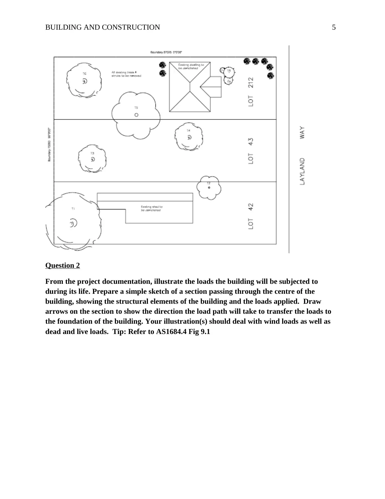
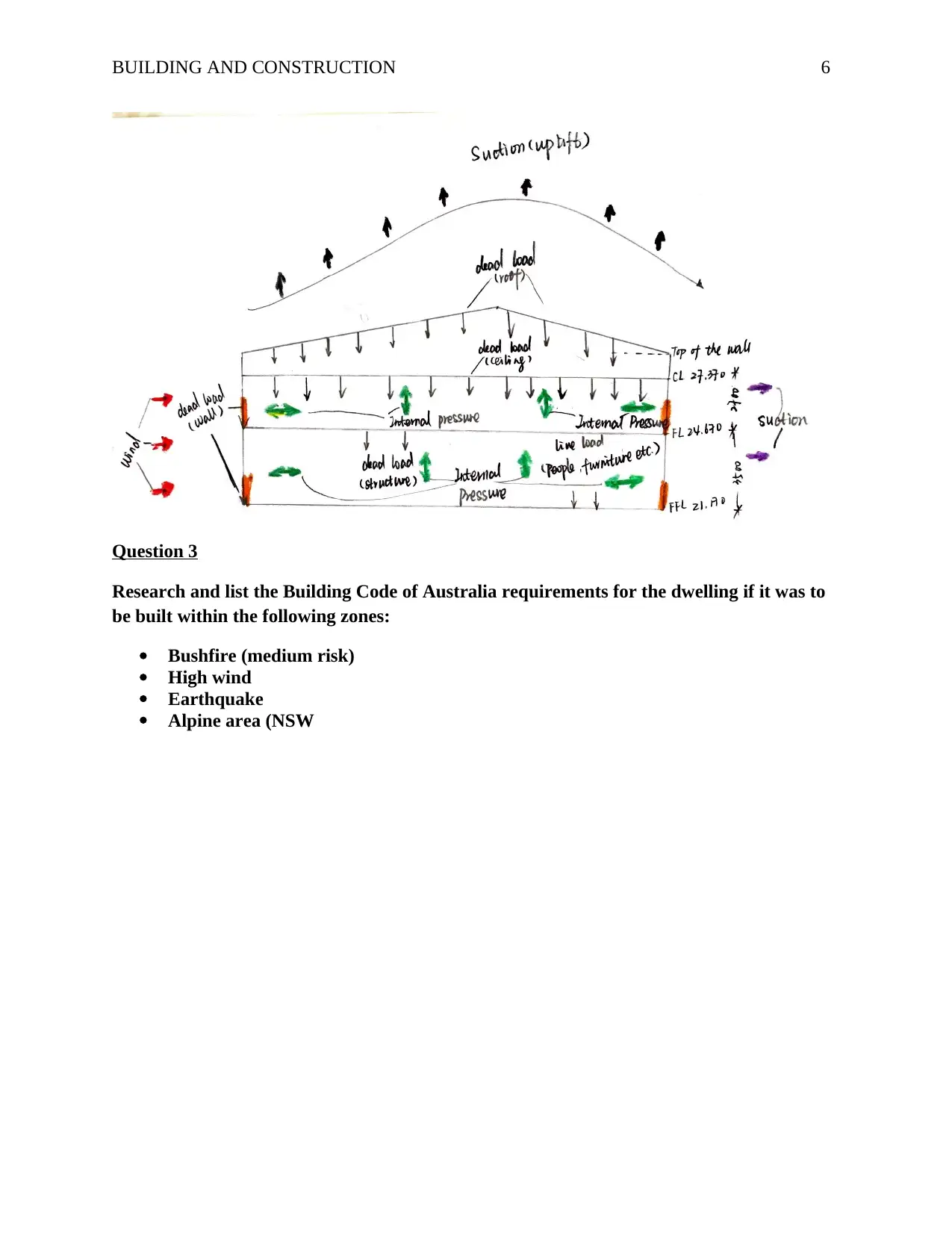
Question 2
From the project documentation, illustrate the loads the building will be subjected to
during its life. Prepare a simple sketch of a section passing through the centre of the
building, showing the structural elements of the building and the loads applied. Draw
arrows on the section to show the direction the load path will take to transfer the loads to
the foundation of the building. Your illustration(s) should deal with wind loads as well as
dead and live loads. Tip: Refer to AS1684.4 Fig 9.1
BUILDING AND CONSTRUCTION 6
Question 3
Research and list the Building Code of Australia requirements for the dwelling if it was to
be built within the following zones:
Bushfire (medium risk)
High wind
Earthquake
Alpine area (NSW
Question 3
Research and list the Building Code of Australia requirements for the dwelling if it was to
be built within the following zones:
Bushfire (medium risk)
High wind
Earthquake
Alpine area (NSW
⊘ This is a preview!⊘
Do you want full access?
Subscribe today to unlock all pages.
Trusted by 1+ million students worldwide
BUILDING AND CONSTRUCTION 7
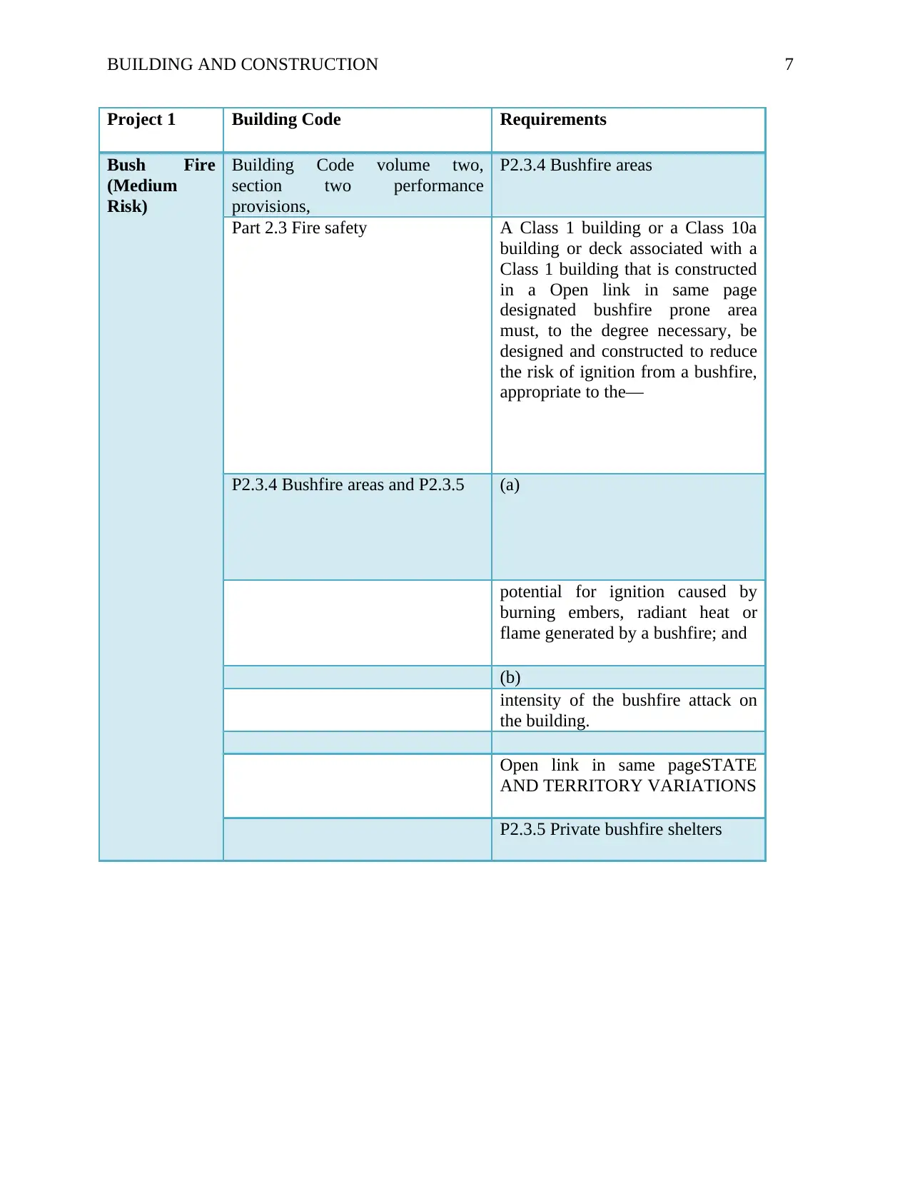
Project 1 Building Code Requirements
Bush Fire
(Medium
Risk)
Building Code volume two,
section two performance
provisions,
P2.3.4 Bushfire areas
Part 2.3 Fire safety A Class 1 building or a Class 10a
building or deck associated with a
Class 1 building that is constructed
in a Open link in same page
designated bushfire prone area
must, to the degree necessary, be
designed and constructed to reduce
the risk of ignition from a bushfire,
appropriate to the—
P2.3.4 Bushfire areas and P2.3.5 (a)
potential for ignition caused by
burning embers, radiant heat or
flame generated by a bushfire; and
(b)
intensity of the bushfire attack on
the building.
Open link in same pageSTATE
AND TERRITORY VARIATIONS
P2.3.5 Private bushfire shelters
Paraphrase This Document
Need a fresh take? Get an instant paraphrase of this document with our AI Paraphraser
BUILDING AND CONSTRUCTION 8
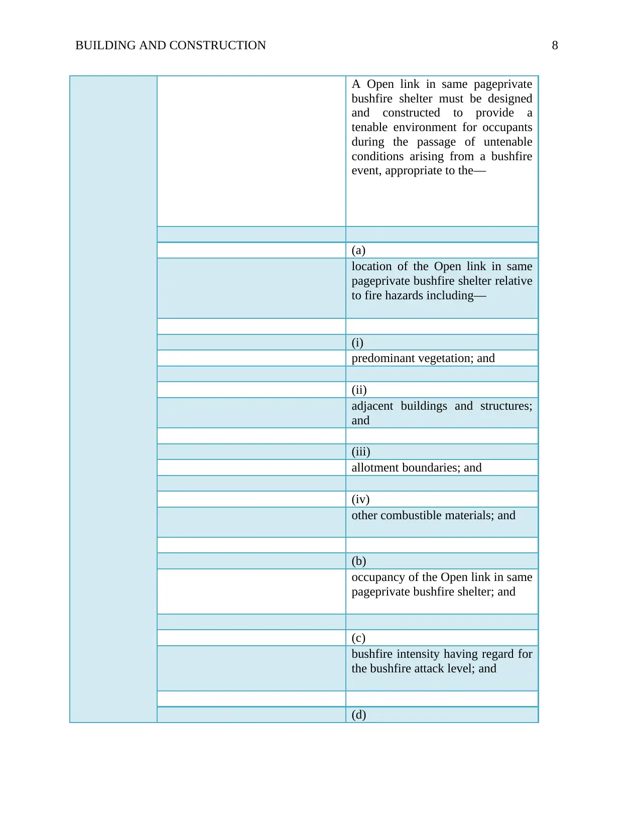
A Open link in same pageprivate
bushfire shelter must be designed
and constructed to provide a
tenable environment for occupants
during the passage of untenable
conditions arising from a bushfire
event, appropriate to the—
(a)
location of the Open link in same
pageprivate bushfire shelter relative
to fire hazards including—
(i)
predominant vegetation; and
(ii)
adjacent buildings and structures;
and
(iii)
allotment boundaries; and
(iv)
other combustible materials; and
(b)
occupancy of the Open link in same
pageprivate bushfire shelter; and
(c)
bushfire intensity having regard for
the bushfire attack level; and
(d)
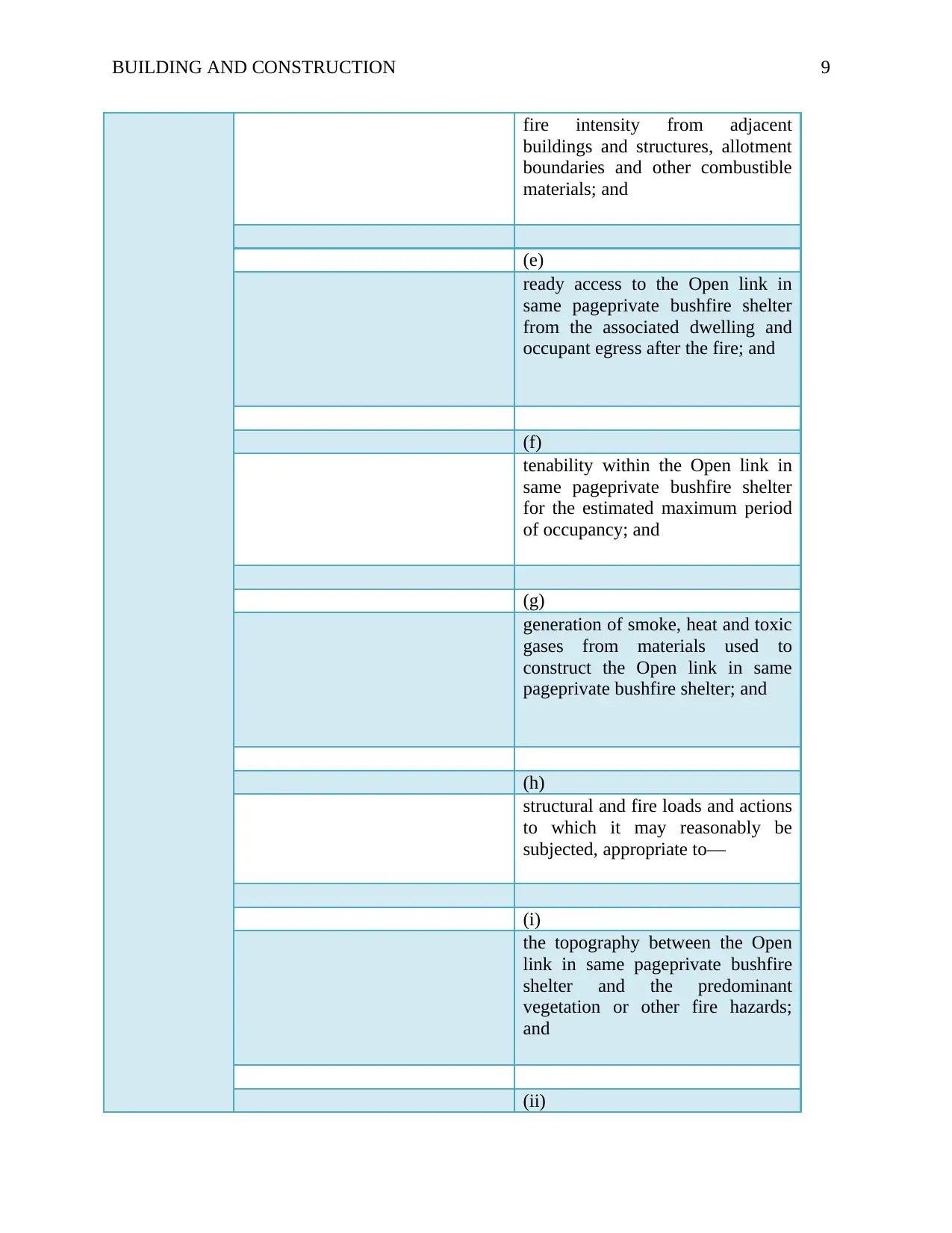
BUILDING AND CONSTRUCTION 9
fire intensity from adjacent
buildings and structures, allotment
boundaries and other combustible
materials; and
(e)
ready access to the Open link in
same pageprivate bushfire shelter
from the associated dwelling and
occupant egress after the fire; and
(f)
tenability within the Open link in
same pageprivate bushfire shelter
for the estimated maximum period
of occupancy; and
(g)
generation of smoke, heat and toxic
gases from materials used to
construct the Open link in same
pageprivate bushfire shelter; and
(h)
structural and fire loads and actions
to which it may reasonably be
subjected, appropriate to—
(i)
the topography between the Open
link in same pageprivate bushfire
shelter and the predominant
vegetation or other fire hazards;
and
(ii)
⊘ This is a preview!⊘
Do you want full access?
Subscribe today to unlock all pages.
Trusted by 1+ million students worldwide
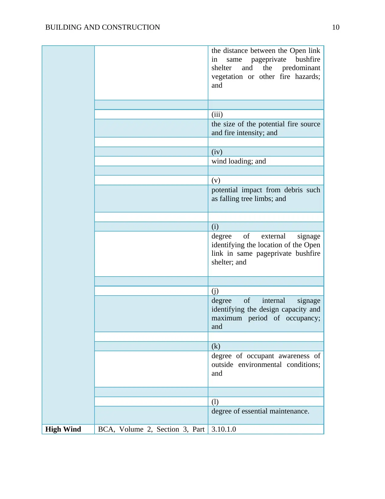
BUILDING AND CONSTRUCTION 10
the distance between the Open link
in same pageprivate bushfire
shelter and the predominant
vegetation or other fire hazards;
and
(iii)
the size of the potential fire source
and fire intensity; and
(iv)
wind loading; and
(v)
potential impact from debris such
as falling tree limbs; and
(i)
degree of external signage
identifying the location of the Open
link in same pageprivate bushfire
shelter; and
(j)
degree of internal signage
identifying the design capacity and
maximum period of occupancy;
and
(k)
degree of occupant awareness of
outside environmental conditions;
and
(l)
degree of essential maintenance.
High Wind BCA, Volume 2, Section 3, Part 3.10.1.0
Paraphrase This Document
Need a fresh take? Get an instant paraphrase of this document with our AI Paraphraser
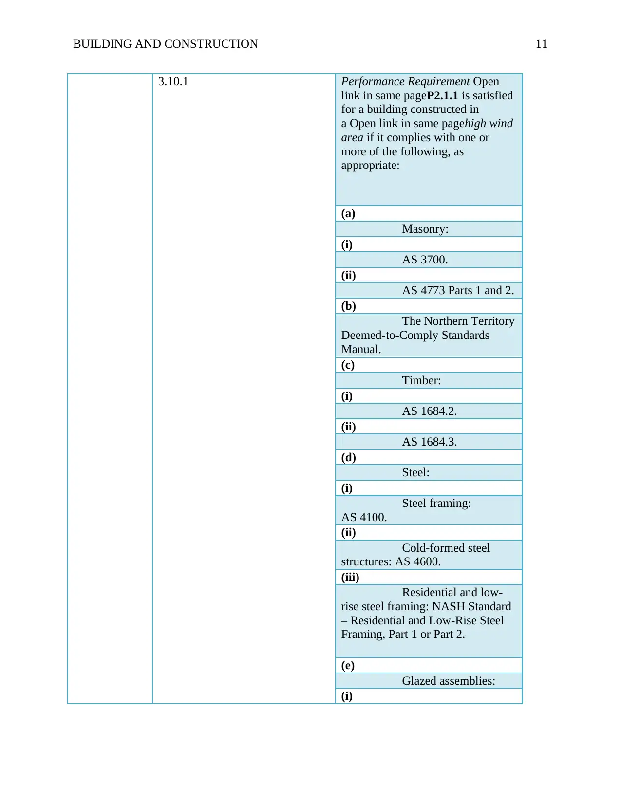
BUILDING AND CONSTRUCTION 11
3.10.1 Performance Requirement Open
link in same pageP2.1.1 is satisfied
for a building constructed in
a Open link in same pagehigh wind
area if it complies with one or
more of the following, as
appropriate:
(a)
Masonry:
(i)
AS 3700.
(ii)
AS 4773 Parts 1 and 2.
(b)
The Northern Territory
Deemed-to-Comply Standards
Manual.
(c)
Timber:
(i)
AS 1684.2.
(ii)
AS 1684.3.
(d)
Steel:
(i)
Steel framing:
AS 4100.
(ii)
Cold-formed steel
structures: AS 4600.
(iii)
Residential and low-
rise steel framing: NASH Standard
– Residential and Low-Rise Steel
Framing, Part 1 or Part 2.
(e)
Glazed assemblies:
(i)
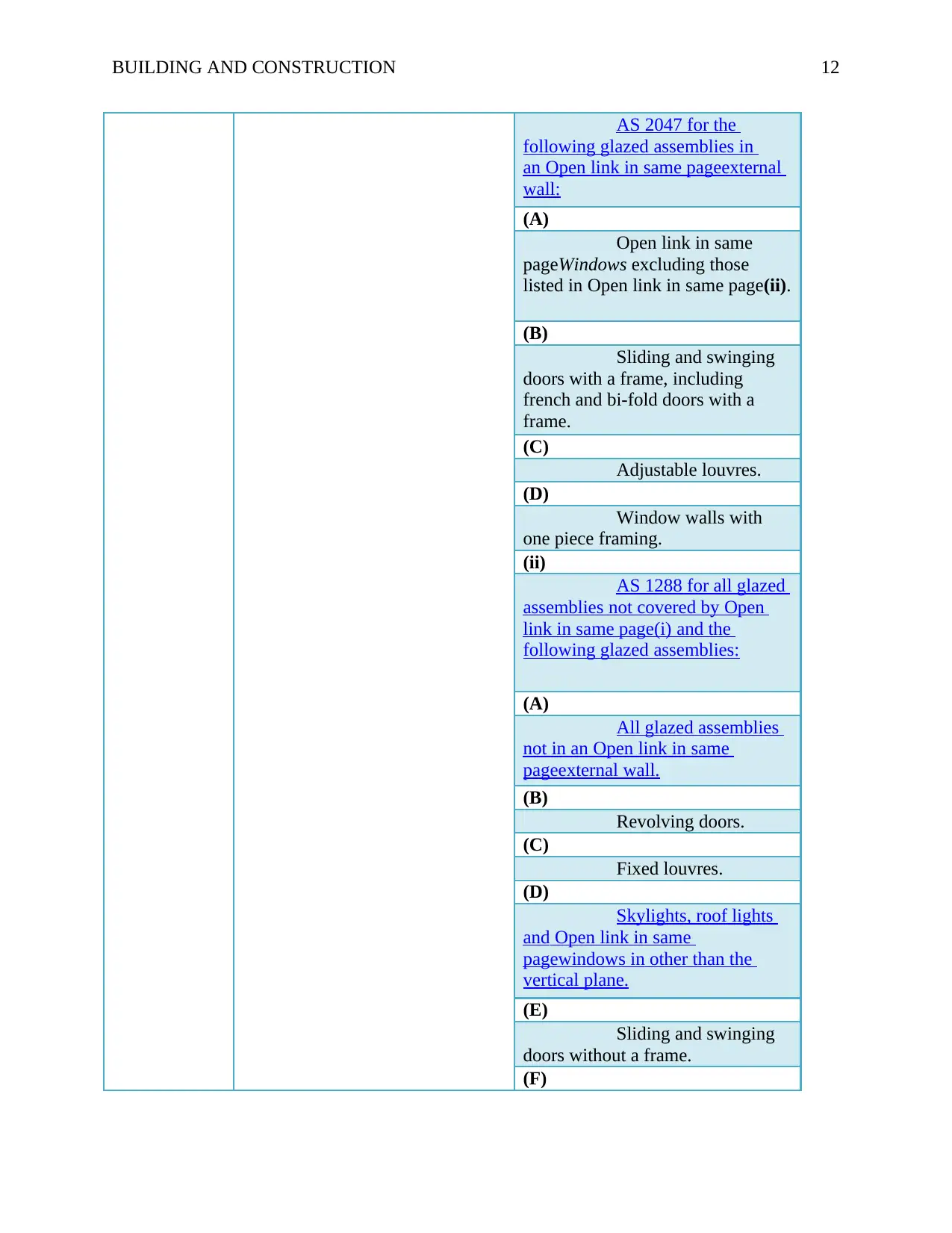
BUILDING AND CONSTRUCTION 12
AS 2047 for the
following glazed assemblies in
an Open link in same pageexternal
wall:
(A)
Open link in same
pageWindows excluding those
listed in Open link in same page(ii).
(B)
Sliding and swinging
doors with a frame, including
french and bi-fold doors with a
frame.
(C)
Adjustable louvres.
(D)
Window walls with
one piece framing.
(ii)
AS 1288 for all glazed
assemblies not covered by Open
link in same page(i) and the
following glazed assemblies:
(A)
All glazed assemblies
not in an Open link in same
pageexternal wall.
(B)
Revolving doors.
(C)
Fixed louvres.
(D)
Skylights, roof lights
and Open link in same
pagewindows in other than the
vertical plane.
(E)
Sliding and swinging
doors without a frame.
(F)
⊘ This is a preview!⊘
Do you want full access?
Subscribe today to unlock all pages.
Trusted by 1+ million students worldwide
1 out of 40
Related Documents


Your All-in-One AI-Powered Toolkit for Academic Success.
+13062052269
info@desklib.com
Available 24*7 on WhatsApp / Email
![[object Object]](/_next/static/media/star-bottom.7253800d.svg)
Unlock your academic potential
Copyright © 2020–2026 A2Z Services. All Rights Reserved. Developed and managed by ZUCOL.