MSc Building Services Engineering Control Systems Assignment 2017/18
VerifiedAdded on 2020/04/13
|11
|2413
|51
Project
AI Summary
This assignment analyzes control systems for room heating, focusing on open and closed loop configurations. It examines the relationship between the control signal and radiator output, considering assumptions like zero initial conditions and uniform inputs. The project explores transfer functions, including the derivation of closed-loop transfer functions and characteristic equations, and the impact of proportional feedback controllers. It investigates the effects of proportional control, steady-state errors, and potential improvements using PI and PID controllers, while also addressing the influence of transport delays, the reasonableness of assumptions regarding heat output, and the inclusion of infiltration heat loss in the system. The assignment provides a comprehensive understanding of control system design and analysis within the context of building services engineering.
BRUNEL UNIVERSITY
MSc in Building Services Engineering
Building Management and Control Systems
CONTROL SYSTEMS ASSIGNMENT 2017/18
Student Name
Student Registration Number
Course Code
Date of submission
MSc in Building Services Engineering
Building Management and Control Systems
CONTROL SYSTEMS ASSIGNMENT 2017/18
Student Name
Student Registration Number
Course Code
Date of submission
Paraphrase This Document
Need a fresh take? Get an instant paraphrase of this document with our AI Paraphraser
Introduction
A control system consists of interconnected components designed to achieve a desired
purpose. Some of the modern control engineering practice includes the use of control design
strategies for the improvement of manufacturing processes, the efficiency of energy use,
advanced automobile control, as well as rapid transit. The control of the heating of a room
forming the basis of the control system. The thermal response of a particular room was modelled
as a first order system with a time constant of 20 minutes. Control systems are used to determine
the inputs to a system and they equally govern the outputs as intended (Basilio, 2002). There are
two types of control, the open and closed loop control. The open loop control does not have a
feedback section in the system. There is no way to monitor the process to find out if the output is
obtained as intended. The controller in an open loop system may operate an actuator or a switch
to adjust the input to the process. The closed loop control system, on the other hand, has a
feedback system. The feedback system can be positive or negative depending on the design of
the system (Ogata, n.d).
This assignment seeks to find out more information on how to control the heating of a
room using a radiator. The radiator should get inputs from the surrounding and the controller
adjusts the temperature according to the room heat requirements. The control engineers are often
faced with the central problem in control of finding a technically feasible way to act on a given
process so that the process behaves as closely as possible to the desired behavior. The
approximate behavior should be achieved in the face of uncertainty of the process and in the
presence of uncontrollable external disturbances acting on the process. The major objectives of
the controller design are to achieve speed, accuracy and system stability (Wang, n.d.).
Assumption
(i) The heating of the room is achieved using a LPHW panel radiator.
(ii) The room temperature was regulated using an electric heater of variable output W
watts.
(iii) The heat output from this radiator can be controlled by adjusting the LPHW flow rate.
(iv) The relationship between the flow rate and the radiator output can be approximately
by a first order transfer function with a time constant of one minute.
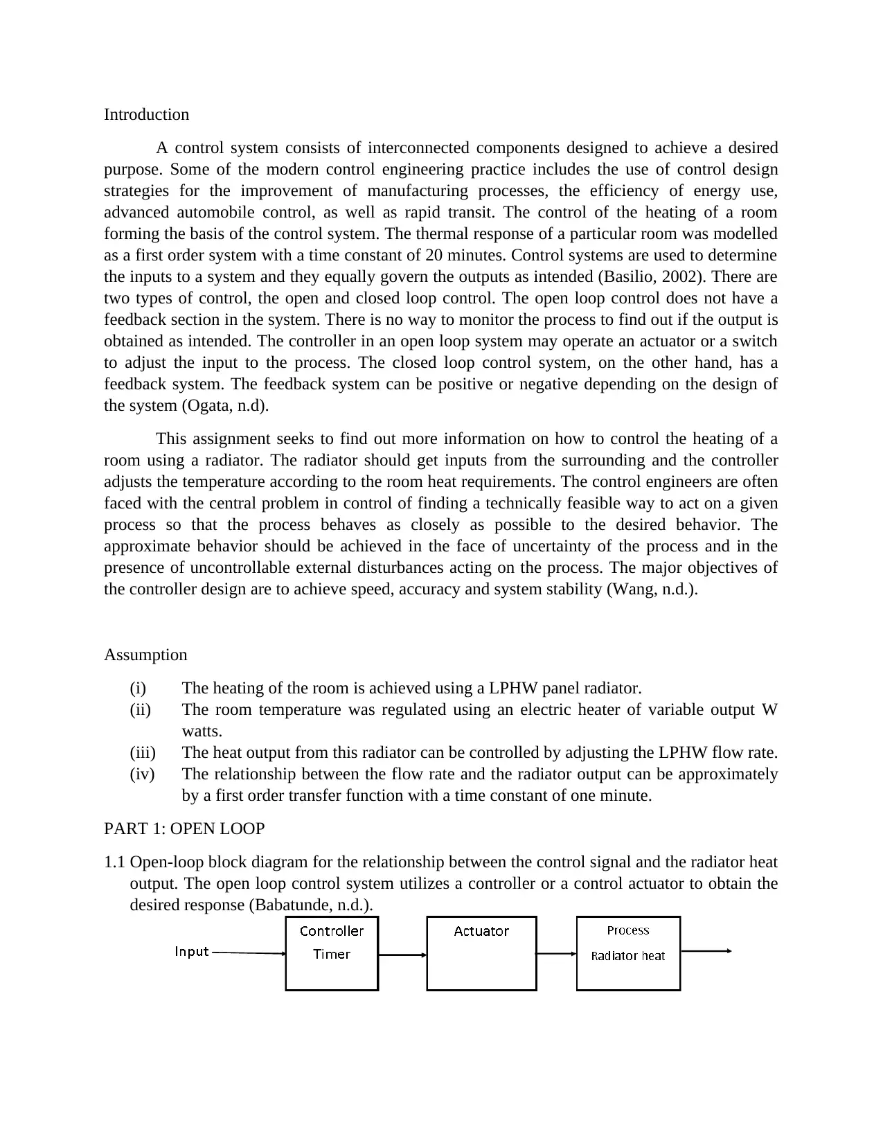
PART 1: OPEN LOOP
1.1 Open-loop block diagram for the relationship between the control signal and the radiator heat
output. The open loop control system utilizes a controller or a control actuator to obtain the
desired response (Babatunde, n.d.).
A control system consists of interconnected components designed to achieve a desired
purpose. Some of the modern control engineering practice includes the use of control design
strategies for the improvement of manufacturing processes, the efficiency of energy use,
advanced automobile control, as well as rapid transit. The control of the heating of a room
forming the basis of the control system. The thermal response of a particular room was modelled
as a first order system with a time constant of 20 minutes. Control systems are used to determine
the inputs to a system and they equally govern the outputs as intended (Basilio, 2002). There are
two types of control, the open and closed loop control. The open loop control does not have a
feedback section in the system. There is no way to monitor the process to find out if the output is
obtained as intended. The controller in an open loop system may operate an actuator or a switch
to adjust the input to the process. The closed loop control system, on the other hand, has a
feedback system. The feedback system can be positive or negative depending on the design of
the system (Ogata, n.d).
This assignment seeks to find out more information on how to control the heating of a
room using a radiator. The radiator should get inputs from the surrounding and the controller
adjusts the temperature according to the room heat requirements. The control engineers are often
faced with the central problem in control of finding a technically feasible way to act on a given
process so that the process behaves as closely as possible to the desired behavior. The
approximate behavior should be achieved in the face of uncertainty of the process and in the
presence of uncontrollable external disturbances acting on the process. The major objectives of
the controller design are to achieve speed, accuracy and system stability (Wang, n.d.).
Assumption
(i) The heating of the room is achieved using a LPHW panel radiator.
(ii) The room temperature was regulated using an electric heater of variable output W
watts.
(iii) The heat output from this radiator can be controlled by adjusting the LPHW flow rate.
(iv) The relationship between the flow rate and the radiator output can be approximately
by a first order transfer function with a time constant of one minute.
PART 1: OPEN LOOP
1.1 Open-loop block diagram for the relationship between the control signal and the radiator heat
output. The open loop control system utilizes a controller or a control actuator to obtain the
desired response (Babatunde, n.d.).
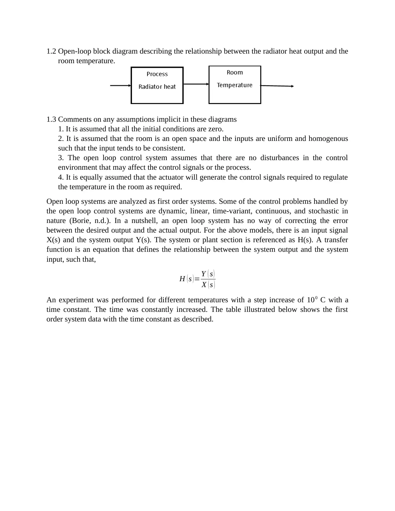
1.2 Open-loop block diagram describing the relationship between the radiator heat output and the
room temperature.
1.3 Comments on any assumptions implicit in these diagrams
1. It is assumed that all the initial conditions are zero.
2. It is assumed that the room is an open space and the inputs are uniform and homogenous
such that the input tends to be consistent.
3. The open loop control system assumes that there are no disturbances in the control
environment that may affect the control signals or the process.
4. It is equally assumed that the actuator will generate the control signals required to regulate
the temperature in the room as required.
Open loop systems are analyzed as first order systems. Some of the control problems handled by
the open loop control systems are dynamic, linear, time-variant, continuous, and stochastic in
nature (Borie, n.d.). In a nutshell, an open loop system has no way of correcting the error
between the desired output and the actual output. For the above models, there is an input signal
X(s) and the system output Y(s). The system or plant section is referenced as H(s). A transfer
function is an equation that defines the relationship between the system output and the system
input, such that,
H ( s ) = Y ( s )
X ( s )
An experiment was performed for different temperatures with a step increase of 100 C with a
time constant. The time was constantly increased. The table illustrated below shows the first
order system data with the time constant as described.
⊘ This is a preview!⊘
Do you want full access?
Subscribe today to unlock all pages.
Trusted by 1+ million students worldwide
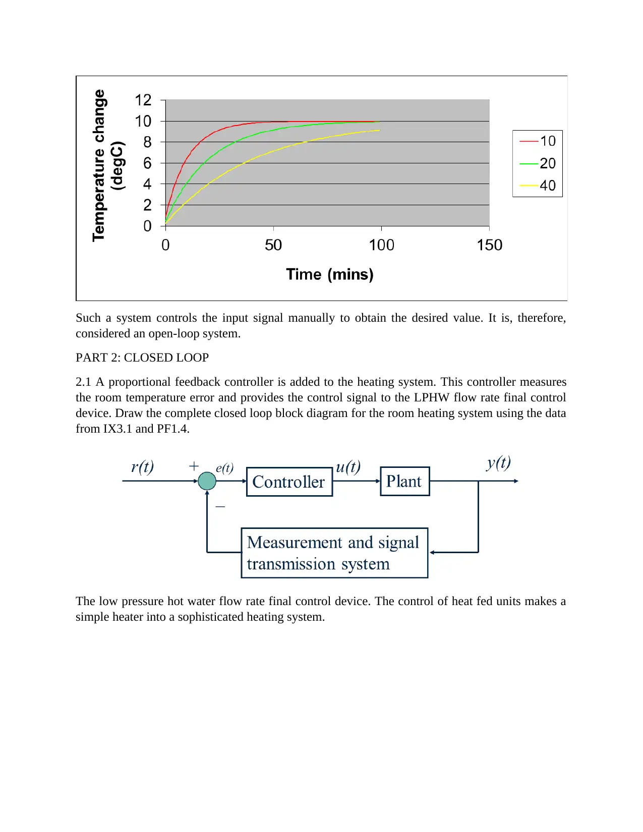
Such a system controls the input signal manually to obtain the desired value. It is, therefore,
considered an open-loop system.
PART 2: CLOSED LOOP
2.1 A proportional feedback controller is added to the heating system. This controller measures
the room temperature error and provides the control signal to the LPHW flow rate final control
device. Draw the complete closed loop block diagram for the room heating system using the data
from IX3.1 and PF1.4.
The low pressure hot water flow rate final control device. The control of heat fed units makes a
simple heater into a sophisticated heating system.
Paraphrase This Document
Need a fresh take? Get an instant paraphrase of this document with our AI Paraphraser
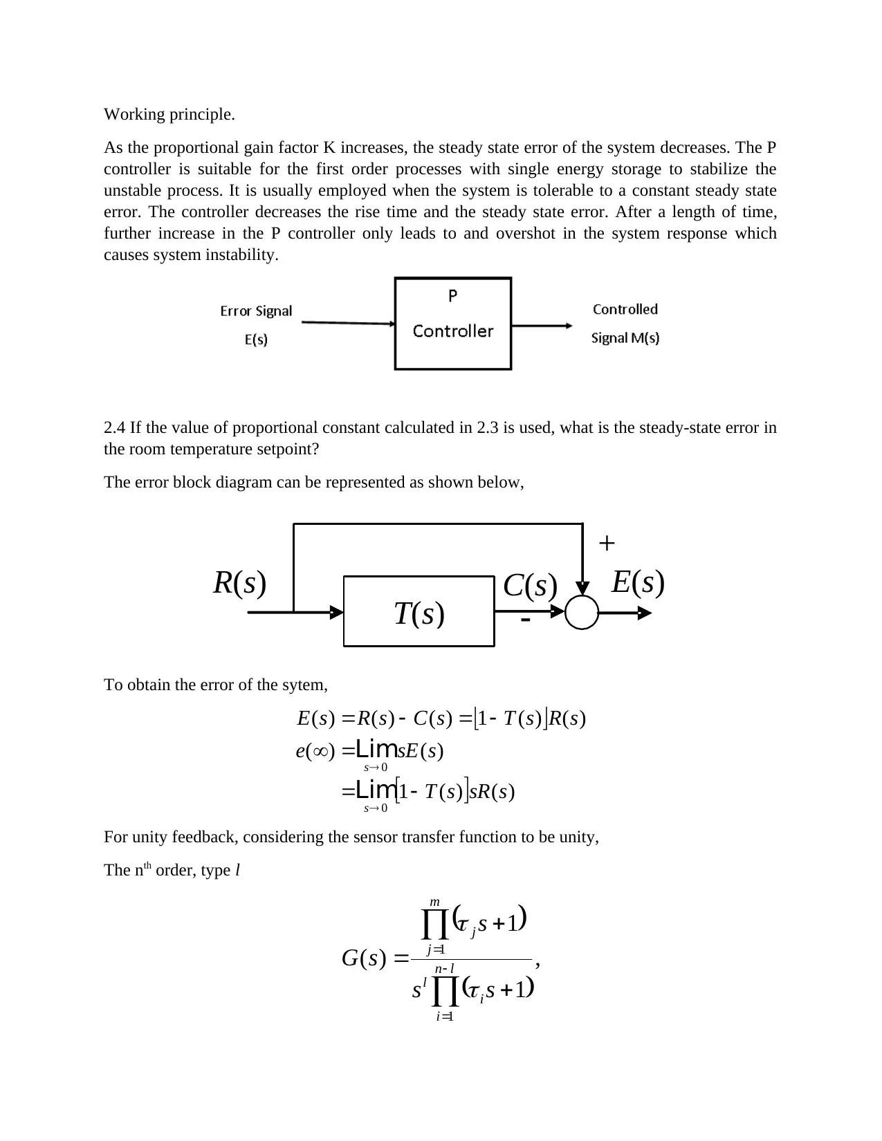
2.2 derive the closed loop transfer function relating the outside air temperature to the inside air
temperature and the characteristic equation for the closed loop system.
The closed loop transfer function has been illustrated in the time domain. The Laplace transform
is easier to use for mathematical computations. The illustration below demonstrates the same
closed loop using the S-domain.
The controller is also referred to as the actuator and the system is the radiator in this case study.
The output shows the temperature that is felt in the room. There are different control types that
can be implemented in the feedback loop system. There is the proportional, proportional-integral,
proportional-derivative, and the proportional-integral-derivative controller.
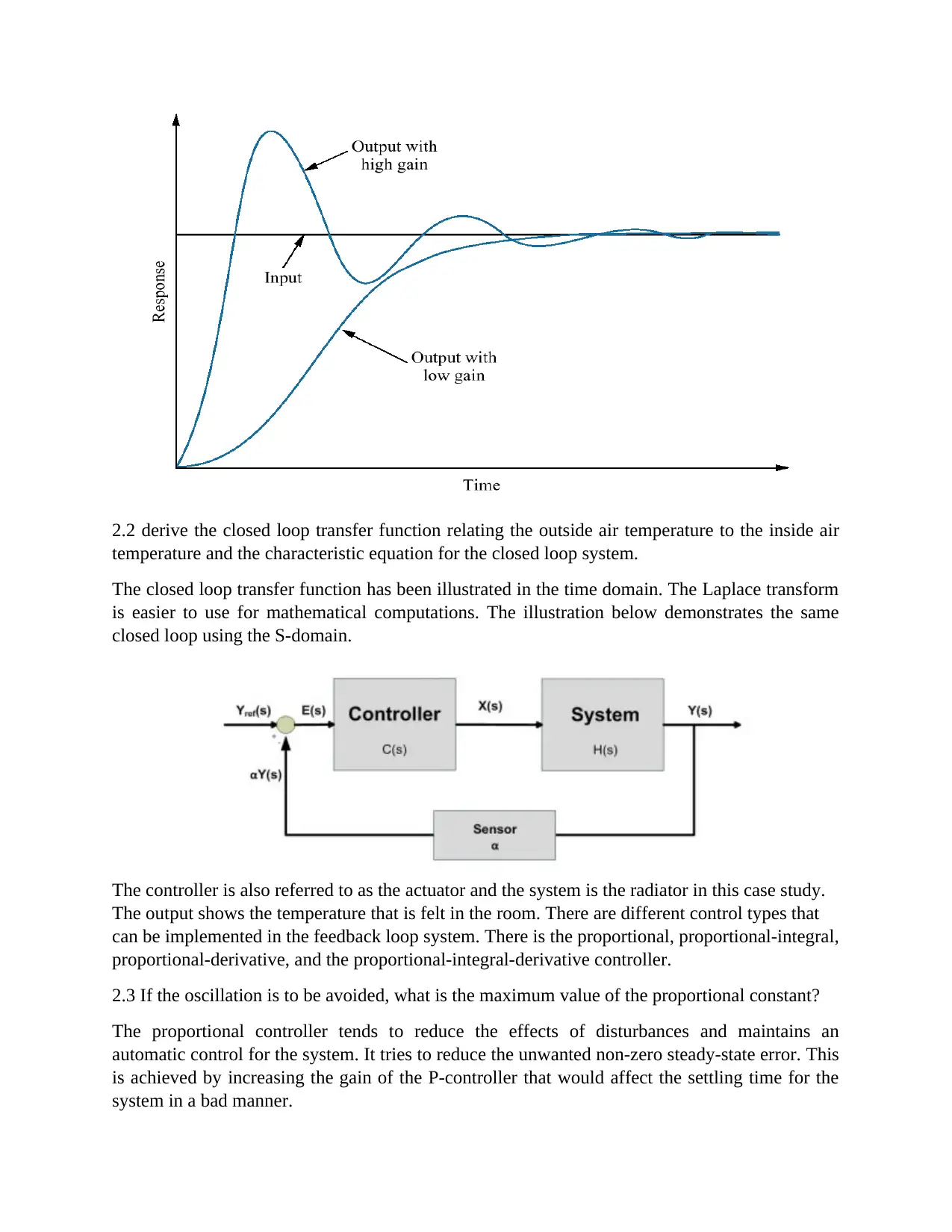
2.3 If the oscillation is to be avoided, what is the maximum value of the proportional constant?
The proportional controller tends to reduce the effects of disturbances and maintains an
automatic control for the system. It tries to reduce the unwanted non-zero steady-state error. This
is achieved by increasing the gain of the P-controller that would affect the settling time for the
system in a bad manner.
temperature and the characteristic equation for the closed loop system.
The closed loop transfer function has been illustrated in the time domain. The Laplace transform
is easier to use for mathematical computations. The illustration below demonstrates the same
closed loop using the S-domain.
The controller is also referred to as the actuator and the system is the radiator in this case study.
The output shows the temperature that is felt in the room. There are different control types that
can be implemented in the feedback loop system. There is the proportional, proportional-integral,
proportional-derivative, and the proportional-integral-derivative controller.
2.3 If the oscillation is to be avoided, what is the maximum value of the proportional constant?
The proportional controller tends to reduce the effects of disturbances and maintains an
automatic control for the system. It tries to reduce the unwanted non-zero steady-state error. This
is achieved by increasing the gain of the P-controller that would affect the settling time for the
system in a bad manner.
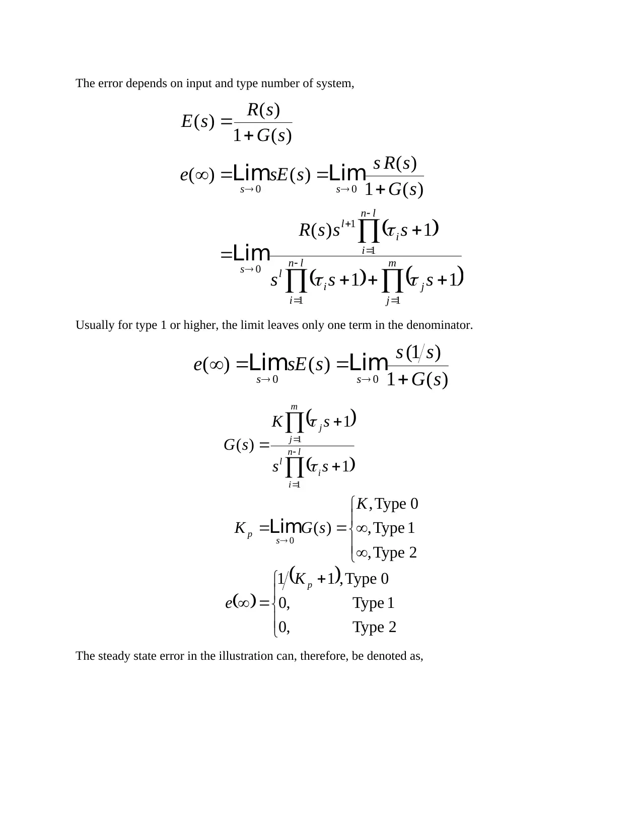
Working principle.
As the proportional gain factor K increases, the steady state error of the system decreases. The P
controller is suitable for the first order processes with single energy storage to stabilize the
unstable process. It is usually employed when the system is tolerable to a constant steady state
error. The controller decreases the rise time and the steady state error. After a length of time,
further increase in the P controller only leads to and overshot in the system response which
causes system instability.
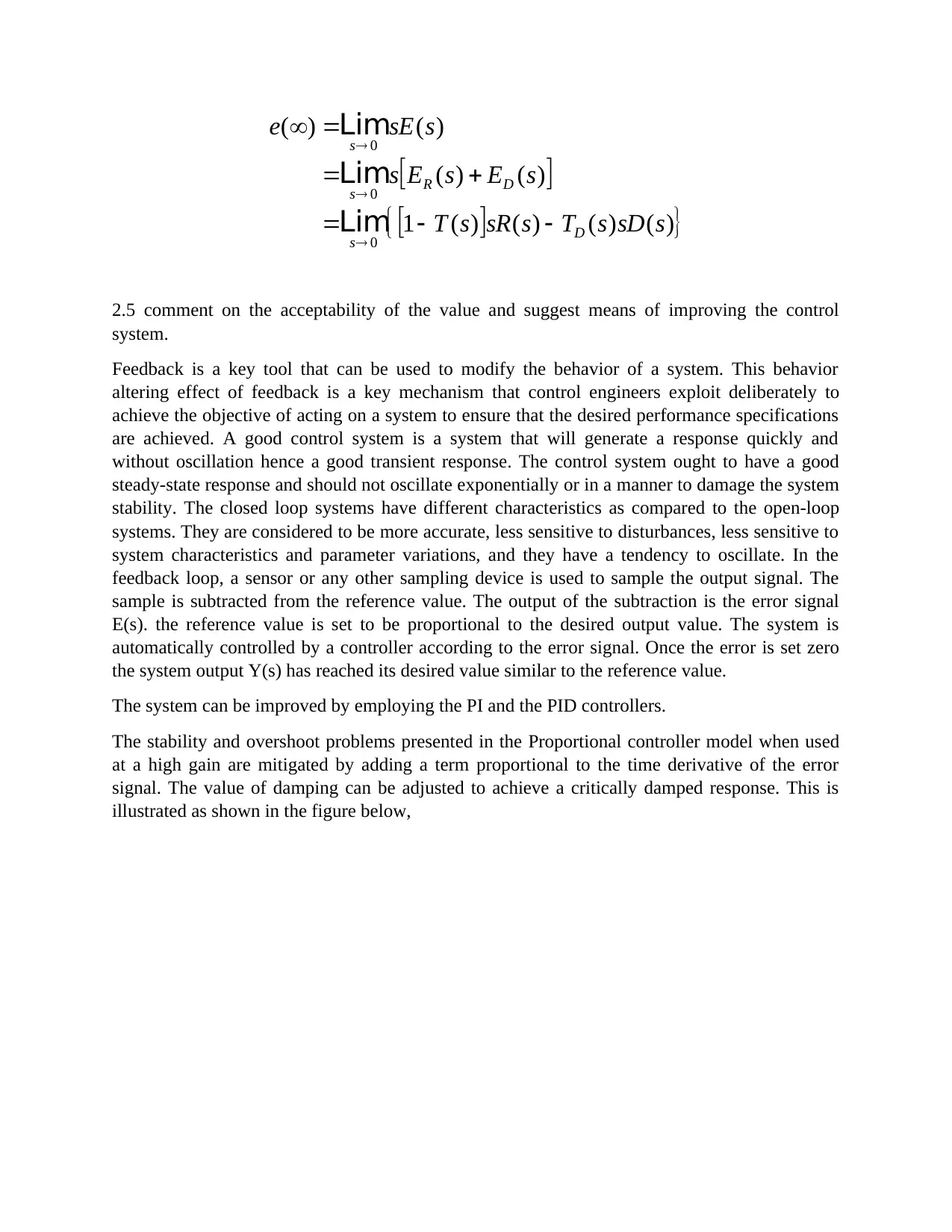
2.4 If the value of proportional constant calculated in 2.3 is used, what is the steady-state error in
the room temperature setpoint?
The error block diagram can be represented as shown below,
T(s)
R(s) E(s)
+
C(s)
To obtain the error of the sytem,
)()(1
)()(
)()(1)()()(
0
0
ssRsT
ssEe
sRsTsCsRsE
s
s
Lim
Lim
For unity feedback, considering the sensor transfer function to be unity,
The nth order, type l
,
1
1
)(
1
1
ln
i
i
l
m
j
j
ss
s
sG
As the proportional gain factor K increases, the steady state error of the system decreases. The P
controller is suitable for the first order processes with single energy storage to stabilize the
unstable process. It is usually employed when the system is tolerable to a constant steady state
error. The controller decreases the rise time and the steady state error. After a length of time,
further increase in the P controller only leads to and overshot in the system response which
causes system instability.
2.4 If the value of proportional constant calculated in 2.3 is used, what is the steady-state error in
the room temperature setpoint?
The error block diagram can be represented as shown below,
T(s)
R(s) E(s)
+
C(s)
To obtain the error of the sytem,
)()(1
)()(
)()(1)()()(
0
0
ssRsT
ssEe
sRsTsCsRsE
s
s
Lim
Lim
For unity feedback, considering the sensor transfer function to be unity,
The nth order, type l
,
1
1
)(
1
1
ln
i
i
l
m
j
j
ss
s
sG
⊘ This is a preview!⊘
Do you want full access?
Subscribe today to unlock all pages.
Trusted by 1+ million students worldwide
The error depends on input and type number of system,
m
j
j
ln
i
i
l
ln
i
i
l
s
ss
sss
sssR
sG
sRs
ssEe
sG
sR
sE
11
1
1
0
00
11
1)(
)(1
)(
)()(
)(1
)(
)(
Lim
LimLim
Usually for type 1 or higher, the limit leaves only one term in the denominator.
)(1
)1(
)()( 00 sG
ss
ssEe ss
LimLim
2Type,0
1Type,0
0Type,11
2Type,
1Type,
0Type,
)(
1
1
)(
0
1
1
p
s
p
ln
i
i
l
m
j
j
K
e
K
sGK
ss
sK
sG
Lim
The steady state error in the illustration can, therefore, be denoted as,
m
j
j
ln
i
i
l
ln
i
i
l
s
ss
sss
sssR
sG
sRs
ssEe
sG
sR
sE
11
1
1
0
00
11
1)(
)(1
)(
)()(
)(1
)(
)(
Lim
LimLim
Usually for type 1 or higher, the limit leaves only one term in the denominator.
)(1
)1(
)()( 00 sG
ss
ssEe ss
LimLim
2Type,0
1Type,0
0Type,11
2Type,
1Type,
0Type,
)(
1
1
)(
0
1
1
p
s
p
ln
i
i
l
m
j
j
K
e
K
sGK
ss
sK
sG
Lim
The steady state error in the illustration can, therefore, be denoted as,
Paraphrase This Document
Need a fresh take? Get an instant paraphrase of this document with our AI Paraphraser
)()()()(1
)()(
)()(
0
0
0
ssDsTssRsT
sEsEs
ssEe
D
s
DR
s
s
Lim
Lim
Lim
2.5 comment on the acceptability of the value and suggest means of improving the control
system.
Feedback is a key tool that can be used to modify the behavior of a system. This behavior
altering effect of feedback is a key mechanism that control engineers exploit deliberately to
achieve the objective of acting on a system to ensure that the desired performance specifications
are achieved. A good control system is a system that will generate a response quickly and
without oscillation hence a good transient response. The control system ought to have a good
steady-state response and should not oscillate exponentially or in a manner to damage the system
stability. The closed loop systems have different characteristics as compared to the open-loop
systems. They are considered to be more accurate, less sensitive to disturbances, less sensitive to
system characteristics and parameter variations, and they have a tendency to oscillate. In the
feedback loop, a sensor or any other sampling device is used to sample the output signal. The
sample is subtracted from the reference value. The output of the subtraction is the error signal
E(s). the reference value is set to be proportional to the desired output value. The system is
automatically controlled by a controller according to the error signal. Once the error is set zero
the system output Y(s) has reached its desired value similar to the reference value.
The system can be improved by employing the PI and the PID controllers.
The stability and overshoot problems presented in the Proportional controller model when used
at a high gain are mitigated by adding a term proportional to the time derivative of the error
signal. The value of damping can be adjusted to achieve a critically damped response. This is
illustrated as shown in the figure below,
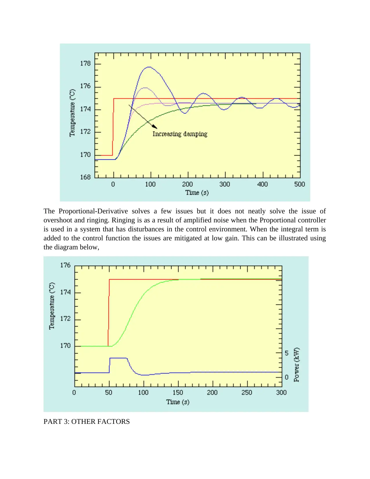
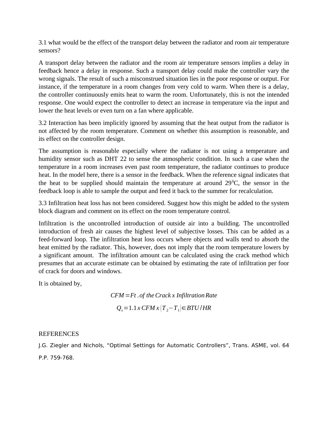
The Proportional-Derivative solves a few issues but it does not neatly solve the issue of
overshoot and ringing. Ringing is as a result of amplified noise when the Proportional controller
is used in a system that has disturbances in the control environment. When the integral term is
added to the control function the issues are mitigated at low gain. This can be illustrated using
the diagram below,
PART 3: OTHER FACTORS
⊘ This is a preview!⊘
Do you want full access?
Subscribe today to unlock all pages.
Trusted by 1+ million students worldwide
3.1 what would be the effect of the transport delay between the radiator and room air temperature
sensors?
A transport delay between the radiator and the room air temperature sensors implies a delay in
feedback hence a delay in response. Such a transport delay could make the controller vary the
wrong signals. The result of such a misconstrued situation lies in the poor response or output. For
instance, if the temperature in a room changes from very cold to warm. When there is a delay,
the controller continuously emits heat to warm the room. Unfortunately, this is not the intended
response. One would expect the controller to detect an increase in temperature via the input and
lower the heat levels or even turn on a fan where applicable.
3.2 Interaction has been implicitly ignored by assuming that the heat output from the radiator is
not affected by the room temperature. Comment on whether this assumption is reasonable, and
its effect on the controller design.
The assumption is reasonable especially where the radiator is not using a temperature and
humidity sensor such as DHT 22 to sense the atmospheric condition. In such a case when the
temperature in a room increases even past room temperature, the radiator continues to produce
heat. In the model here, there is a sensor in the feedback. When the reference signal indicates that
the heat to be supplied should maintain the temperature at around 290C, the sensor in the
feedback loop is able to sample the output and feed it back to the summer for recalculation.
3.3 Infiltration heat loss has not been considered. Suggest how this might be added to the system
block diagram and comment on its effect on the room temperature control.
Infiltration is the uncontrolled introduction of outside air into a building. The uncontrolled
introduction of fresh air causes the highest level of subjective losses. This can be added as a
feed-forward loop. The infiltration heat loss occurs where objects and walls tend to absorb the
heat emitted by the radiator. This, however, does not imply that the room temperature lowers by
a significant amount. The infiltration amount can be calculated using the crack method which
presumes that an accurate estimate can be obtained by estimating the rate of infiltration per foor
of crack for doors and windows.
It is obtained by,
CFM =Ft .of the Crack x Infiltration Rate
Qs =1.1 x CFM x ( T 2−T1 ) ∈BTU /HR
REFERENCES
J.G. Ziegler and Nichols, “Optimal Settings for Automatic Controllers”, Trans. ASME, vol. 64
P.P. 759-768.
Paraphrase This Document
Need a fresh take? Get an instant paraphrase of this document with our AI Paraphraser
K.J. Astrom and T. Haughland, “Automatic Tuning of PID Controllers”, 1st ed. Research
Triangle Park, NC:
Instrum. Soc. Amer.
K. Ogata, “Modern Control Engineering”, 3rd ed. Upper saddle River, NJ: Prentice- Hall.
J.C. Basilio and S.R. Matos, “Design of PI and PID Controllers with Transient Performance
Specification”, IEEE Transactions on Education, Vol. 45, No. 4, November 2002.
Salim Ahmed, Biao Huang, Sirish L. shah, “Novel identification Method from Step Response”,
Control Engineering Practice 15 (2007), 545-550, Science Direct.
Saeed Tavakoli, Mahdi Tavakoli, “ Optimal Tuning of PID Controller for First Order Plus Time
Delay Models Using Dimensional Analysis”, The Fourth International Conference on Control
and Automation (ICCA’ 03), 10-12 June 2003, Montreal, Canada.
Abdul Aziz Ishak, Muhammad Azlan Hussain, “ Reformulation of the Tangent Method for PID
Controller Tuning”, Procedding to TENCON 2000, IEEE region 10, Kuala Lumper, 24-27 Sept.
2000.
Qing-Gao Wang, Tong-Heng Lee, Ho-Wang Fung, Qiang Bi and Yu Zhang, “ PID Tuning for
Improved Performance”, IEEE transactions on Control Systems Technology, Vol. 7, No.4, n.d.
Babatunde A. Oqqunaike, W. Harman Ray, “Process Dynamics, Modeling and Control”, 1st ed.
Oxford University Press, Inc.
J.A. Borrie, “Modern Control systems: A Manual of Design Methods”, Prentice Hall
International Ltd., n.d.
1 out of 11
Related Documents


Your All-in-One AI-Powered Toolkit for Academic Success.
+13062052269
info@desklib.com
Available 24*7 on WhatsApp / Email
![[object Object]](/_next/static/media/star-bottom.7253800d.svg)
Unlock your academic potential
Copyright © 2020–2026 A2Z Services. All Rights Reserved. Developed and managed by ZUCOL.