Comprehensive Report: Building Systems and Structural Analysis

Verified

Added on  2020/04/15

|27
|1880
|48
Report
AI Summary
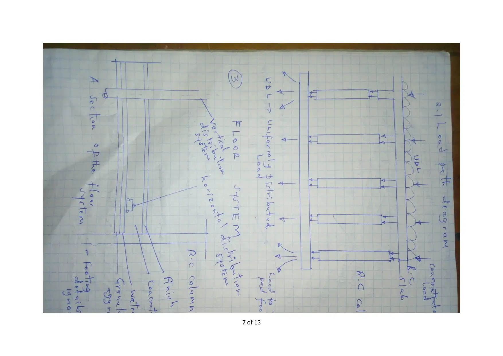
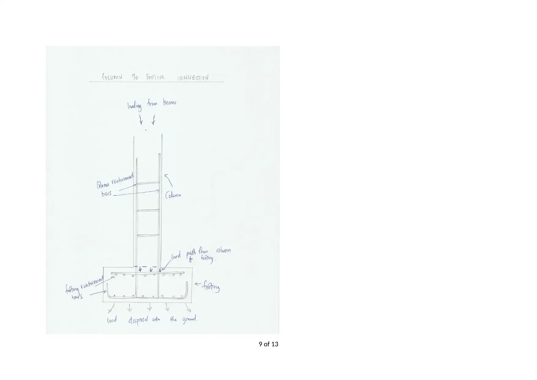
This report provides a comprehensive overview of various building systems commonly used in civil engineering projects. It begins with an analysis of the footing system, comparing pad footings and strip footings, and considering soil conditions. The report then delves into structural systems, illustrating load paths and the framework of reinforced concrete buildings. It also examines flooring systems, detailing the construction sequence of concrete screed floors and appropriate reinforcement. Wall systems, including brick wall erection, are described, along with a discussion of building services such as access, water management, electrical, HVAC, and fire safety. Finally, the report covers roof systems, specifically shingled cladding, and includes a bibliography for further reference. This report is a valuable resource for civil engineering students seeking to understand building construction and design.
Document Page
NAME
OTEN NUMBER
COMPETENCY NAME AND NUMBER
ASSESSMENT NUMBER
tabler-icon-diamond-filled.svg

Paraphrase This Document

Need a fresh take? Get an instant paraphrase of this document with our AI Paraphraser
Document Page
CONTENTS:
Footing System:.........................................................................................................................1
Structural Systems:.....................................................................................................................3
Flooring System:........................................................................................................................6
Wall Systems:.............................................................................................................................8
Services:...................................................................................................................................10
Roof System:............................................................................................................................11
Bibliography:............................................................................................................................15
ii
Document Page
Figure 1: RC Frame Building under Construction. Source: http://www.stevensconstruction.co.uk/portfolio/view/16/Fulston-Manor-School---
Sittingbourne
1 of 13
Document Page
FOOTING SYSTEM:
Footing is the lower portion of a building which rests on the foundation and is normally designed to carry both live and dead loads of the walling
element while adequately resisting some movements due to soil condition in which it is established. Now, referring to figure 1 above, a pad
footing system can be retrieved. This is the most appropriate foundation system for a medium rise structure as each footing is independent of
each other and they can have different designs catering for the various imposed loads. This makes them ideal for both symmetrical and
unsymmetrical floor plans and building shapes. The load in this case is transferred directly from the columns into the footing and in some case,
more than one column can reside on a single pad footing1. This type of footing is applicable in a wide variety of structural systems ranging from
ordinary moment resisting frames and portal frames to shear wall building frames. This therefore means that they can be used on almost every
building material from concrete to stone. Notably, however, the area in which the building is to be seated is in one of the streets of Victoria and
from various soil tests carried out, it reveals that clay soils could be dominating implying that the soils are verily reactive (this is categorised as
class H according to AS 2870 and AS 1726) hence need to integrate another footing type to accommodate the changing soil properties like
moisture content. AS 2870 provides further technical requirements for this kind of footing. Nevertheless, pad footings are only applicable in
providing support to the columns hence it is normally restrictive to localised vertical support provision. Besides, safeguards on shear and
bending moments will only be sufficient if the concrete mix strength and the reinforcement are appropriately done. Wide strip footings with
integrated piers will therefore come in handy in such conditions of extreme swelling and shrinkage. They have more advantages over other
systems as they allow for either one or more basement levels while being relatively unaffected by changing soil conditions. The piers provide a
firm footing structure against such movements as they are sunk deeper than the normal footings.
The Strip footing system is illustrated in figure 2.
1Murty CV, Goel RK, Goyal A, Jain SK, Sinha R, Rai DC, Arlekar JN, Metzger R. Reinforced concrete structures. (Earthquake spectra, 2002) Jul;18(S1):149-85.
2 of 13
tabler-icon-diamond-filled.svg

Paraphrase This Document

Need a fresh take? Get an instant paraphrase of this document with our AI Paraphraser
Document Page
3 of 13
Document Page
Figure 2: Footing system (front elevation )
Figure 3: Pad footing system (Image courtesy of structuraldrafter.com. available at: http://www.structuraldrafter.com/pad-footing-detail.html)
4 of 13
Document Page
STRUCTURAL SYSTEMS:
Below is a section of the structural framework of a typical RC building.
Figure 2: Structural framework. Source:http://pizza.bellycard.com/concrete-ceiling-construction.html
The picture above shows a slab section with both columns and beams. It is representative of the structure’s framework as these are the
members that support the load from the roof level to the pad footing level. The building has both dead and live loads which must be
accounted for. The live loads include weight of occupants, wind and earthquake, and any other moving or temporary loads. Dead loads
include weight of structural members, snow, wall cladding and permanently fixed items. The loads in a reinforced concrete structure will be
passed down from the roof system to the beams and then columns and also from the slabs to the beams to the columns. From the columns,
they are to be transferred to the pad footing from which they are to be distributed evenly into the surface of the earth for energy dissipation2.
The load transfer path is indicated below.
2Nawy E. Reinforced concrete: A fundamental approach. 2000.
5 of 13
tabler-icon-diamond-filled.svg

Paraphrase This Document

Need a fresh take? Get an instant paraphrase of this document with our AI Paraphraser
Document Page
6 of 13
Document Page
7 of 13
Document Page
Figure 3: Concrete frame load path
8 of 13
tabler-icon-diamond-filled.svg

Paraphrase This Document

Need a fresh take? Get an instant paraphrase of this document with our AI Paraphraser
Document Page
9 of 13
Document Page
10 of 13
chevron_up_icon
1 out of 27
circle_padding
hide_on_mobile
zoom_out_icon
[object Object]