Construction Project Analysis: Bus Repair Facility Report
VerifiedAdded on 2023/03/31
|35
|5380
|76
Report
AI Summary
This report analyzes the construction management of a bus repair facility project in Wellington City. It provides an introduction to the project, including architectural and site plans, and outlines the project information in a table. The report then delves into the planned project data, detailing the approaches to planning, budgeting, project estimation, and scheduling, including the use of Gantt charts and PERT diagrams. A project planned data table is included, summarizing the project duration, budget, and milestones. The report also includes a work breakdown structure, cost pre-estimates, and a cash flow forecast. The analysis extends to the actual project data, discussing industry approaches to tracking, monitoring, and reporting, with figures and tables to support the analysis. The assignment covers all aspects of project management, from initial planning to execution and control, providing a comprehensive overview of construction project management principles and practices.

Construction management
Student name
Institution affiliation
Student name
Institution affiliation
Paraphrase This Document
Need a fresh take? Get an instant paraphrase of this document with our AI Paraphraser
Contents
Q1. Project Information...................................................................................................................3
1.1 introduction...........................................................................................................................3
1.2 project information table............................................................................................................3
Q2. Project planned data..................................................................................................................3
2.1 analyzed approaches..............................................................................................................3
2.2 project planned data table.................................................................................................5
2.3 Appendix................................................................................................................................5
Q3: Analyze Actual Data.................................................................................................................7
3.1 Analyzing industry approaches.............................................................................................7
3.2 Project Actual Data Table......................................................................................................8
3.3 Appendices.............................................................................................................................8
Figure 1 work breakdown structure, clear copy in excel.................................................................6
Figure 2 cost pre estimates..............................................................................................................8
Figure 3 costs overview, the graph was drawn based on data from the contractor, refer to MS file
for clear copy...................................................................................................................................8
Figure 5 costs overview.................................................................................................................23
Table 1 activity schedule, cost, start, finish date, percentage, milestone, costs time and
dependencies in the project..............................................................................................................8
Table 2 cash flow forecasting........................................................................................................21
Q1. Project Information
1.1 introduction
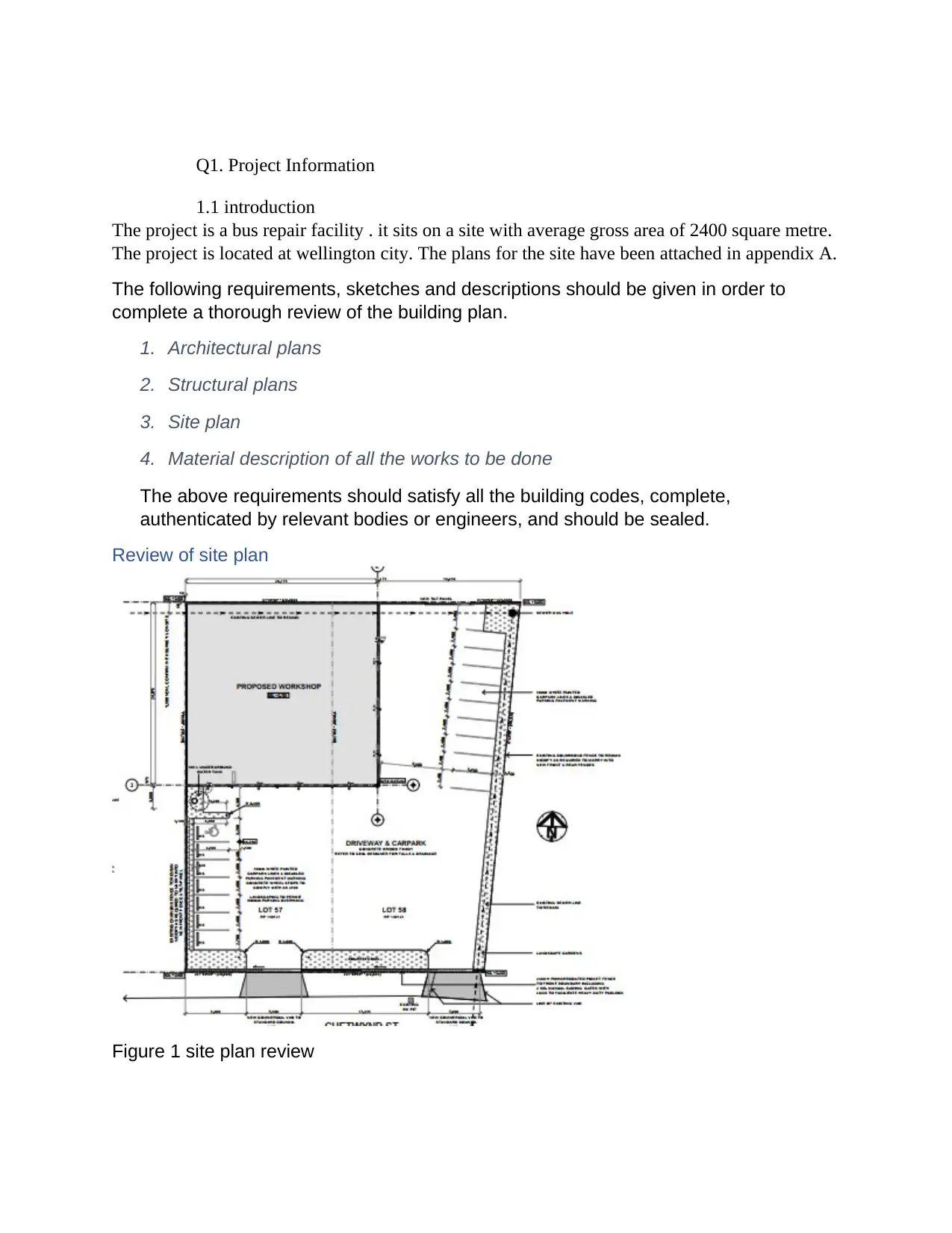
The project is a bus repair facility . it sits on a site with average gross area of 2400 square metre.
The project is located at wellington city. The plans for the site have been attached in appendix A.
The following requirements, sketches and descriptions should be given in order to
complete a thorough review of the building plan.
1. Architectural plans
2. Structural plans
3. Site plan
4. Material description of all the works to be done
The above requirements should satisfy all the building codes, complete,
authenticated by relevant bodies or engineers, and should be sealed.
Review of site plan
Figure 1 site plan review
1.1 introduction
The project is a bus repair facility . it sits on a site with average gross area of 2400 square metre.
The project is located at wellington city. The plans for the site have been attached in appendix A.
The following requirements, sketches and descriptions should be given in order to
complete a thorough review of the building plan.
1. Architectural plans
2. Structural plans
3. Site plan
4. Material description of all the works to be done
The above requirements should satisfy all the building codes, complete,
authenticated by relevant bodies or engineers, and should be sealed.
Review of site plan
Figure 1 site plan review
⊘ This is a preview!⊘
Do you want full access?
Subscribe today to unlock all pages.
Trusted by 1+ million students worldwide
Scale and location of all new buildings and all current site structures have been
provided. Lot rows lengths given . The street grades have been developed and the
grades proposed.
A licensed architect, landscape architect, builder, surveyor or designer shall seal the
drawings in respect of their expertise The plans of the site must be drawn to the engineer’s scale as shown on project
plan. Elevations and heights of the building can be built to the level of the architect. The person or company responsible for the preparation of the letter, name,
telephone and fax numbers, and contact information must be included in site
plan. North arrow, distance, date. Devolution name(s) in the title block, on the cover sheet, and each after sheet, if
necessary, national identity numbers. Data on land, including an adjacent map, legal description and, where
applicable, general description of deed limitations provided.
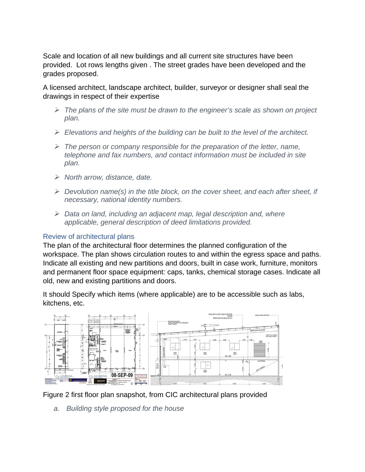
Review of architectural plans
The plan of the architectural floor determines the planned configuration of the
workspace. The plan shows circulation routes to and within the egress space and paths.
Indicate all existing and new partitions and doors, built in case work, furniture, monitors
and permanent floor space equipment: caps, tanks, chemical storage cases. Indicate all
old, new and existing partitions and doors.
It should Specify which items (where applicable) are to be accessible such as labs,
kitchens, etc.
Figure 2 first floor plan snapshot, from CIC architectural plans provided
a. Building style proposed for the house
provided. Lot rows lengths given . The street grades have been developed and the
grades proposed.
A licensed architect, landscape architect, builder, surveyor or designer shall seal the
drawings in respect of their expertise The plans of the site must be drawn to the engineer’s scale as shown on project
plan. Elevations and heights of the building can be built to the level of the architect. The person or company responsible for the preparation of the letter, name,
telephone and fax numbers, and contact information must be included in site
plan. North arrow, distance, date. Devolution name(s) in the title block, on the cover sheet, and each after sheet, if
necessary, national identity numbers. Data on land, including an adjacent map, legal description and, where
applicable, general description of deed limitations provided.
Review of architectural plans
The plan of the architectural floor determines the planned configuration of the
workspace. The plan shows circulation routes to and within the egress space and paths.
Indicate all existing and new partitions and doors, built in case work, furniture, monitors
and permanent floor space equipment: caps, tanks, chemical storage cases. Indicate all
old, new and existing partitions and doors.
It should Specify which items (where applicable) are to be accessible such as labs,
kitchens, etc.
Figure 2 first floor plan snapshot, from CIC architectural plans provided
a. Building style proposed for the house
Paraphrase This Document
Need a fresh take? Get an instant paraphrase of this document with our AI Paraphraser
b. Suitable information and sizes for determining exit modes, including floor loads,
exit design and sizes, halls, gates have been provided
c. Evacuation signs / means, have not been indicated on this plan
d. Description and uses for all areas of the building and the proposed group(s). The
definition of mixed applications (as applicable) have been provided
e. Fully sized drawings to define areas and the height of the house provided.
f. Provisions of access.
g. Definition and descriptions of special arrangements planned, such as a mall
elevated, high-rise, mezzanine, atrium, public garage, etc.
h. Sufficient information, with data that support required scores, to determine fire
resistive construction specifications.
i. Plastic measurements, reinforcement and installation of safety glazing.
j. Fire protection systems information needed
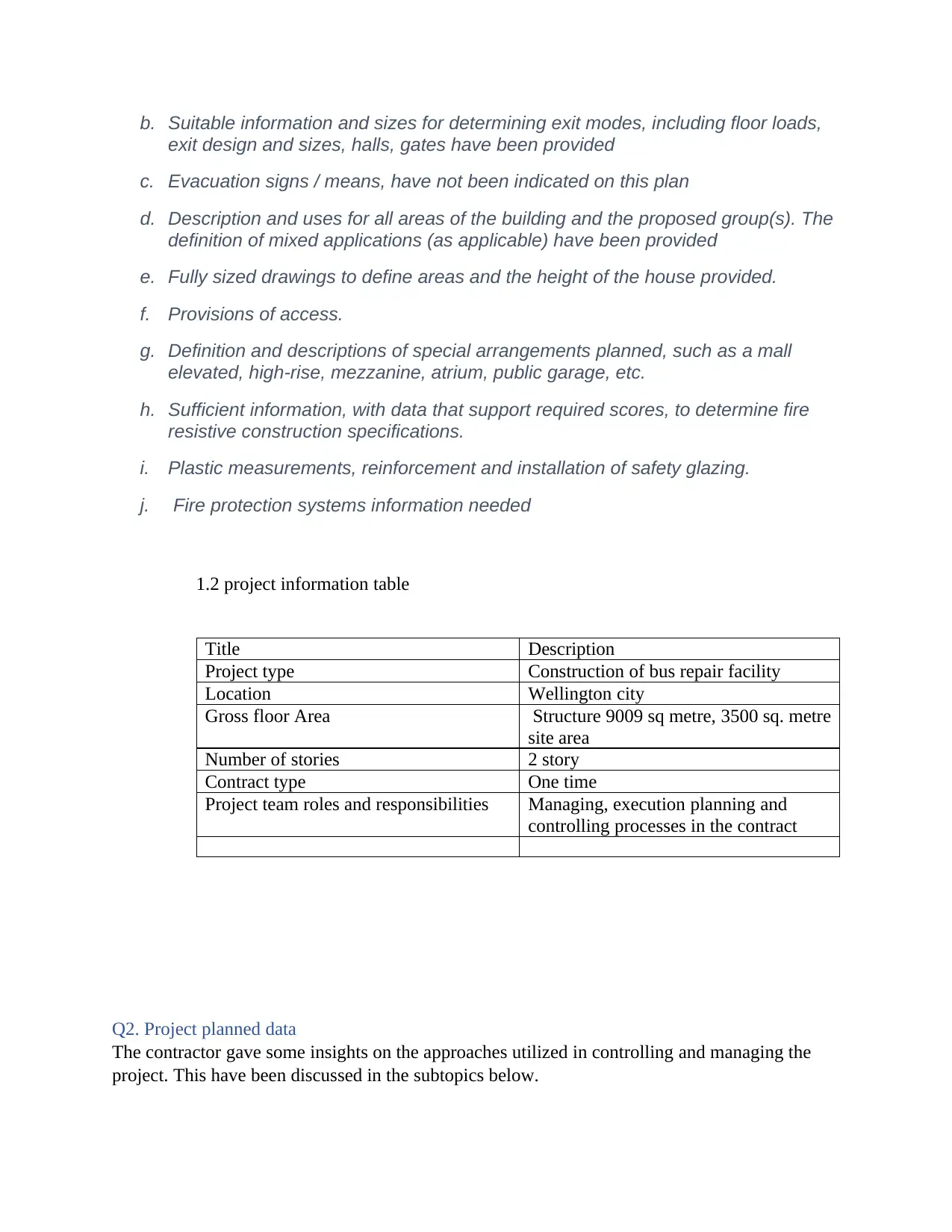
1.2 project information table
Title Description
Project type Construction of bus repair facility
Location Wellington city
Gross floor Area Structure 9009 sq metre, 3500 sq. metre
site area
Number of stories 2 story
Contract type One time
Project team roles and responsibilities Managing, execution planning and
controlling processes in the contract
Q2. Project planned data
The contractor gave some insights on the approaches utilized in controlling and managing the
project. This have been discussed in the subtopics below.
exit design and sizes, halls, gates have been provided
c. Evacuation signs / means, have not been indicated on this plan
d. Description and uses for all areas of the building and the proposed group(s). The
definition of mixed applications (as applicable) have been provided
e. Fully sized drawings to define areas and the height of the house provided.
f. Provisions of access.
g. Definition and descriptions of special arrangements planned, such as a mall
elevated, high-rise, mezzanine, atrium, public garage, etc.
h. Sufficient information, with data that support required scores, to determine fire
resistive construction specifications.
i. Plastic measurements, reinforcement and installation of safety glazing.
j. Fire protection systems information needed
1.2 project information table
Title Description
Project type Construction of bus repair facility
Location Wellington city
Gross floor Area Structure 9009 sq metre, 3500 sq. metre
site area
Number of stories 2 story
Contract type One time
Project team roles and responsibilities Managing, execution planning and
controlling processes in the contract
Q2. Project planned data
The contractor gave some insights on the approaches utilized in controlling and managing the
project. This have been discussed in the subtopics below.
The Building Manager is responsible for supervising the design from beginning to end.
Depending on the project size and complexities, they can individually manage or
collaborate with other building managers. We prepare, budget and supervise
development. It is the responsibility. We will have to determine during the planning
process what resources to use, how to assign staff and build a project schedule. You
have to interact regularly with everyone else on the plan and the customer. They are
always on-call, as if anything goes wrong with the plan, it is their duty. Because of the
variety of jobs in a construction manager, a number of people have advantages in
implementing cloud-based software that helps them prepare, execute and connect from
start to finish.
The following list of activities summarizes the main tasks to be done ins constructing
the building and its surrounding.
Processing of land acquisition, holding, or land and upgrading.
Studies in planning and feasibilities.
Engineering and architectural design.
Building, including construction materials, machinery, and labour.
Financing of construction.
Land insurance and taxes
Owner's general office overhead
Not included in construction equipment and furnishings.
Testing and inspection.
2.1 analyzed approaches
a. planning
In order to support project planning and implementation, the contractor developed participatory
approaches in the project planning . The objective was to create better and sustainable projects
which apply suitable methods to address real problems, especially from a beneficiary or right-
holder perspective in projects based on client’s goals. These strategies also lead to monitoring
and analysis during the project planning process.
The planning approach was based on appreciative inquiry. Based on client’s initiative, resources
and achievements. The objective is to increase the client’s self-esteem and initiative, and
eventually to enhance contractor’s capacity . The clients approach included 4 stages listed below
definition,
hypothesis,
⊘ This is a preview!⊘
Do you want full access?
Subscribe today to unlock all pages.
Trusted by 1+ million students worldwide
design and
destiny
b. budgeting
The project budget was derived using an analogous approach. The contractor had done a similar
project for another client. This made the project budgeting easier.
c. project estimation.
Despite the budgeting, project costs were estimated by the quantity surveyor. The plans of the
proposed structure were used to estimate the project costing and time.
d. project scheduling
Project scheduling is a method for communicating the activities to be carried out and the
administrative resources that are allocated in which time. A project plan is a file that contains
everything needed in time to deliver the project.
The following approaches were used to schedule the project
1. Gant chart - Also known as bar charts are Gantt charts. Activities are shown as bars and
the operation period is the width of each bar. The start date of the bar is indicated and the
end date of the bar is indicated. Both bars can be run sequentially or concurrently
depending on the project execution plan and availability of resources. Gantt Charts can
therefore be easy to understand and manage projects by project management teams and
stakeholders.
2. Pert diagram
Based on the data and information provided by the client, a Ms project document with the
detailed schedule was generated.
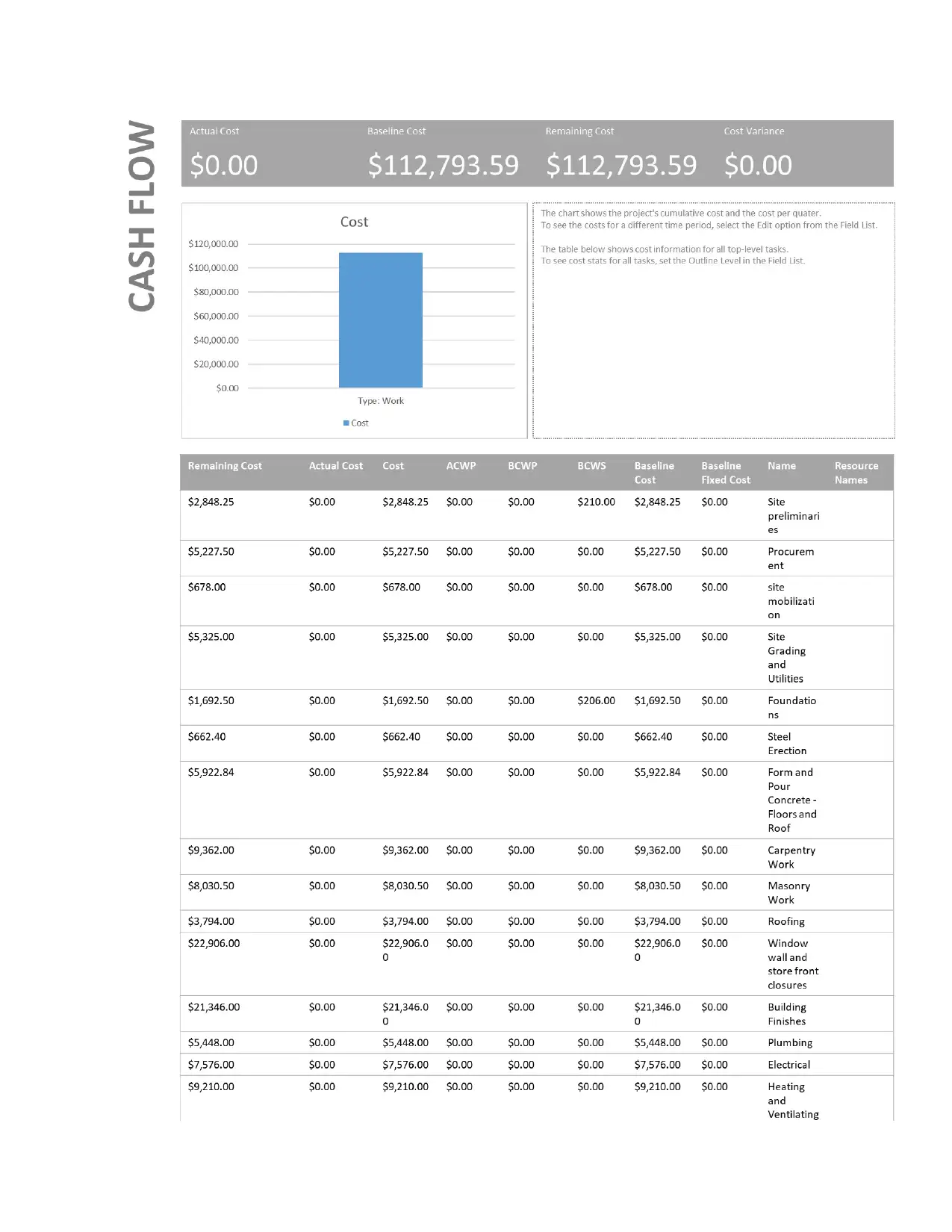
e. cash flow forecasting
Microsoft project was utilised in producing a cash forecast. This has been remodelled and
provided in the appendices
2.2 project planned data table
Title description
Project planned duration 200 days
Estimated budget $300000
Milestones Milestones have been remodeled and
provided in Ms project file
Activities with duration Each activities duration not provided, the
actual data has beeeen used to remodel in
ms project
Interdependencies Project predecessors provided in ms file
destiny
b. budgeting
The project budget was derived using an analogous approach. The contractor had done a similar
project for another client. This made the project budgeting easier.
c. project estimation.
Despite the budgeting, project costs were estimated by the quantity surveyor. The plans of the
proposed structure were used to estimate the project costing and time.
d. project scheduling
Project scheduling is a method for communicating the activities to be carried out and the
administrative resources that are allocated in which time. A project plan is a file that contains
everything needed in time to deliver the project.
The following approaches were used to schedule the project
1. Gant chart - Also known as bar charts are Gantt charts. Activities are shown as bars and
the operation period is the width of each bar. The start date of the bar is indicated and the
end date of the bar is indicated. Both bars can be run sequentially or concurrently
depending on the project execution plan and availability of resources. Gantt Charts can
therefore be easy to understand and manage projects by project management teams and
stakeholders.
2. Pert diagram
Based on the data and information provided by the client, a Ms project document with the
detailed schedule was generated.
e. cash flow forecasting
Microsoft project was utilised in producing a cash forecast. This has been remodelled and
provided in the appendices
2.2 project planned data table
Title description
Project planned duration 200 days
Estimated budget $300000
Milestones Milestones have been remodeled and
provided in Ms project file
Activities with duration Each activities duration not provided, the
actual data has beeeen used to remodel in
ms project
Interdependencies Project predecessors provided in ms file
Paraphrase This Document
Need a fresh take? Get an instant paraphrase of this document with our AI Paraphraser
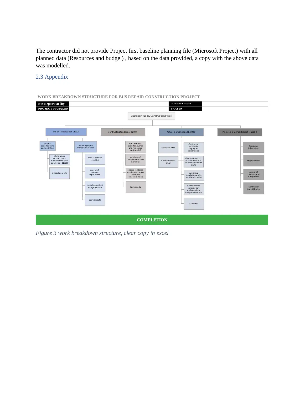
The contractor did not provide Project first baseline planning file (Microsoft Project) with all
planned data (Resources and budge ) , based on the data provided, a copy with the above data
was modelled.
2.3 Appendix
WORK BREAKDOWN STRUCTURE FOR BUS REPAIR CONSTRUCTION PROJECT
Bus Repair Facility COMPANY NAME
PROJECT MANAGER 5-Oct-19
s
COMPLETION
Bus repair fac ility Construc tion Projet
Project idealization (2000)
project
specific ations
and definition
Develop project
management tool
contractors tendering ($2000) Actual C onstruction ($ 60000) Project C lose/ Post Project ( $ 2000 )
all drawings-
arc hitec turals,
structural and civil
approved ( $1000)
sc heduling works
project activity
c hec klist
short brief,
business
implic ations
c ost olan, project
plan generation
submit results
site c leaners (
asbestos, bushes
and remaining
earthworks )
provision of
c omplete detailed
drawings
c hoose tenderes -
mechanical works,
c ivil works,
electric al works
End reports
Switc h off heat
Certify all areas
c lear
Contractor
mobilization
supply of
c onstruc tion
absetos removed,
soils aproved and
c onstruc tion works
starts
surveying,
foundation works -
earthworks, slabs
superstructure
c onstruc tion-
walls,structural
c omponets,buildin
all finishes
Assessthe
deliverables
Project report
Award of
c ertific ate of
c ompletion
Contractor
demobilization
Figure 3 work breakdown structure, clear copy in excel
⊘ This is a preview!⊘
Do you want full access?
Subscribe today to unlock all pages.
Trusted by 1+ million students worldwide
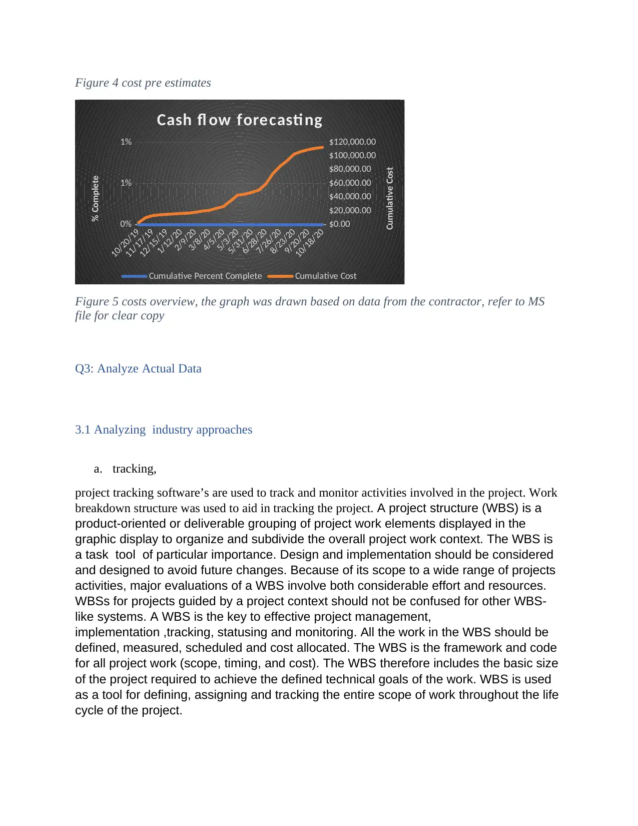
Figure 4 cost pre estimates
10/20/19
11/17/19
12/15/19
1/12/20
2/9/20
3/8/20
4/5/20
5/3/20
5/31/20
6/28/20
7/26/20
8/23/20
9/20/20
10/18/20
0%
1%
1%
$0.00
$20,000.00
$40,000.00
$60,000.00
$80,000.00
$100,000.00
$120,000.00
Cash fl ow forecasti ng
Cumulative Percent Complete Cumulative Cost
% Complete
Cumulative Cost
Figure 5 costs overview, the graph was drawn based on data from the contractor, refer to MS
file for clear copy
Q3: Analyze Actual Data
3.1 Analyzing industry approaches
a. tracking,
project tracking software’s are used to track and monitor activities involved in the project. Work
breakdown structure was used to aid in tracking the project. A project structure (WBS) is a
product-oriented or deliverable grouping of project work elements displayed in the
graphic display to organize and subdivide the overall project work context. The WBS is
a task tool of particular importance. Design and implementation should be considered
and designed to avoid future changes. Because of its scope to a wide range of projects
activities, major evaluations of a WBS involve both considerable effort and resources.
WBSs for projects guided by a project context should not be confused for other WBS-
like systems. A WBS is the key to effective project management,
implementation ,tracking, statusing and monitoring. All the work in the WBS should be
defined, measured, scheduled and cost allocated. The WBS is the framework and code
for all project work (scope, timing, and cost). The WBS therefore includes the basic size
of the project required to achieve the defined technical goals of the work. WBS is used
as a tool for defining, assigning and tracking the entire scope of work throughout the life
cycle of the project.
Paraphrase This Document
Need a fresh take? Get an instant paraphrase of this document with our AI Paraphraser
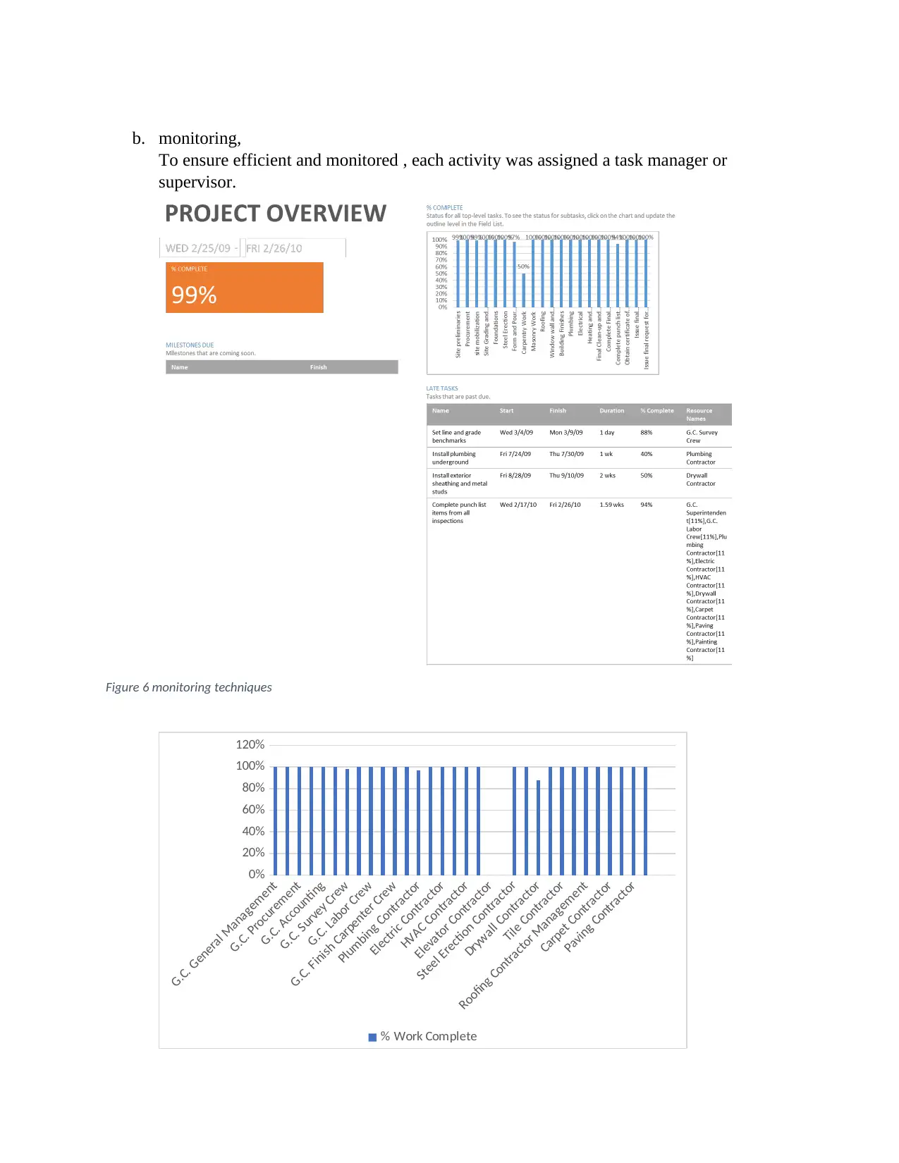
b. monitoring,
To ensure efficient and monitored , each activity was assigned a task manager or
supervisor.
Figure 6 monitoring techniques
G.C. General Management
G.C. Procurement
G.C. Accounting
G.C. Survey Crew
G.C. Labor Crew
G.C. Finish Carpenter Crew
Plumbing Contractor
Electric Contractor
HVAC Contractor
Elevator Contractor
Steel Erection Contractor
Drywall Contractor
Tile Contractor
Roofing Contractor Management
Carpet Contractor
Paving Contractor
0%
20%
40%
60%
80%
100%
120%
% Work Complete
c. reporting and,
The reports are done by unit manager, who communicates to the project manager,
d. controlling
To ensure efficient and control in management, each activity was assigned a task manager or
supervisor.
The resource histogram for the project was as shown below
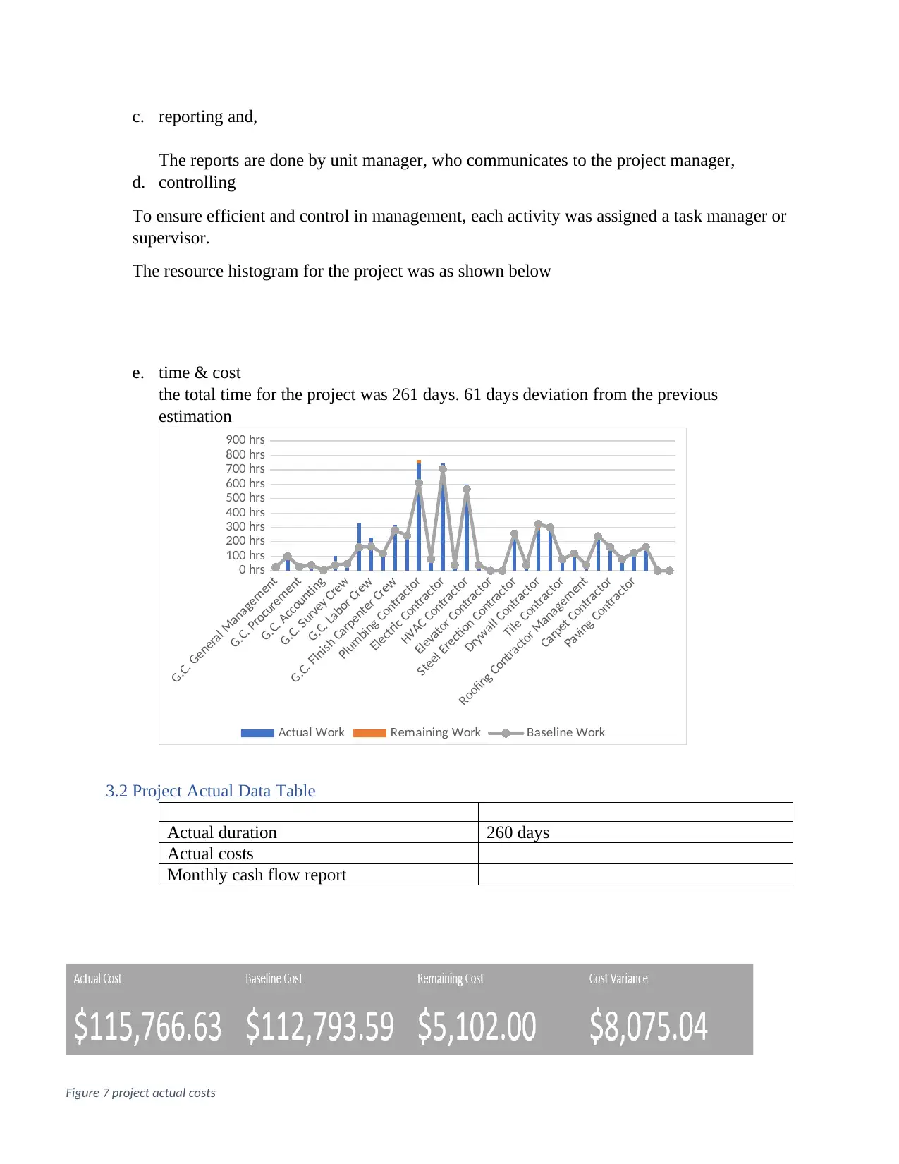
e. time & cost
the total time for the project was 261 days. 61 days deviation from the previous
estimation
G.C. General Management
G.C. Procurement
G.C. Accounting
G.C. Survey Crew
G.C. Labor Crew
G.C. Finish Carpenter Crew
Plumbing Contractor
Electric Contractor
HVAC Contractor
Elevator Contractor
Steel Erection Contractor
Drywall Contractor
Tile Contractor
Roofing Contractor Management
Carpet Contractor
Paving Contractor
0 hrs
100 hrs
200 hrs
300 hrs
400 hrs
500 hrs
600 hrs
700 hrs
800 hrs
900 hrs
Actual Work Remaining Work Baseline Work
3.2 Project Actual Data Table
Actual duration 260 days
Actual costs
Monthly cash flow report
Figure 7 project actual costs
The reports are done by unit manager, who communicates to the project manager,
d. controlling
To ensure efficient and control in management, each activity was assigned a task manager or
supervisor.
The resource histogram for the project was as shown below
e. time & cost
the total time for the project was 261 days. 61 days deviation from the previous
estimation
G.C. General Management
G.C. Procurement
G.C. Accounting
G.C. Survey Crew
G.C. Labor Crew
G.C. Finish Carpenter Crew
Plumbing Contractor
Electric Contractor
HVAC Contractor
Elevator Contractor
Steel Erection Contractor
Drywall Contractor
Tile Contractor
Roofing Contractor Management
Carpet Contractor
Paving Contractor
0 hrs
100 hrs
200 hrs
300 hrs
400 hrs
500 hrs
600 hrs
700 hrs
800 hrs
900 hrs
Actual Work Remaining Work Baseline Work
3.2 Project Actual Data Table
Actual duration 260 days
Actual costs
Monthly cash flow report
Figure 7 project actual costs
⊘ This is a preview!⊘
Do you want full access?
Subscribe today to unlock all pages.
Trusted by 1+ million students worldwide
1 out of 35
Related Documents


Your All-in-One AI-Powered Toolkit for Academic Success.
+13062052269
info@desklib.com
Available 24*7 on WhatsApp / Email
![[object Object]](/_next/static/media/star-bottom.7253800d.svg)
Unlock your academic potential
Copyright © 2020–2026 A2Z Services. All Rights Reserved. Developed and managed by ZUCOL.