Analysis of Op-Amps: Butterworth, Bessel, Chebyshev Filters Report

Verified

Added on  2023/03/30

|8
|643
|125
Report
AI Summary
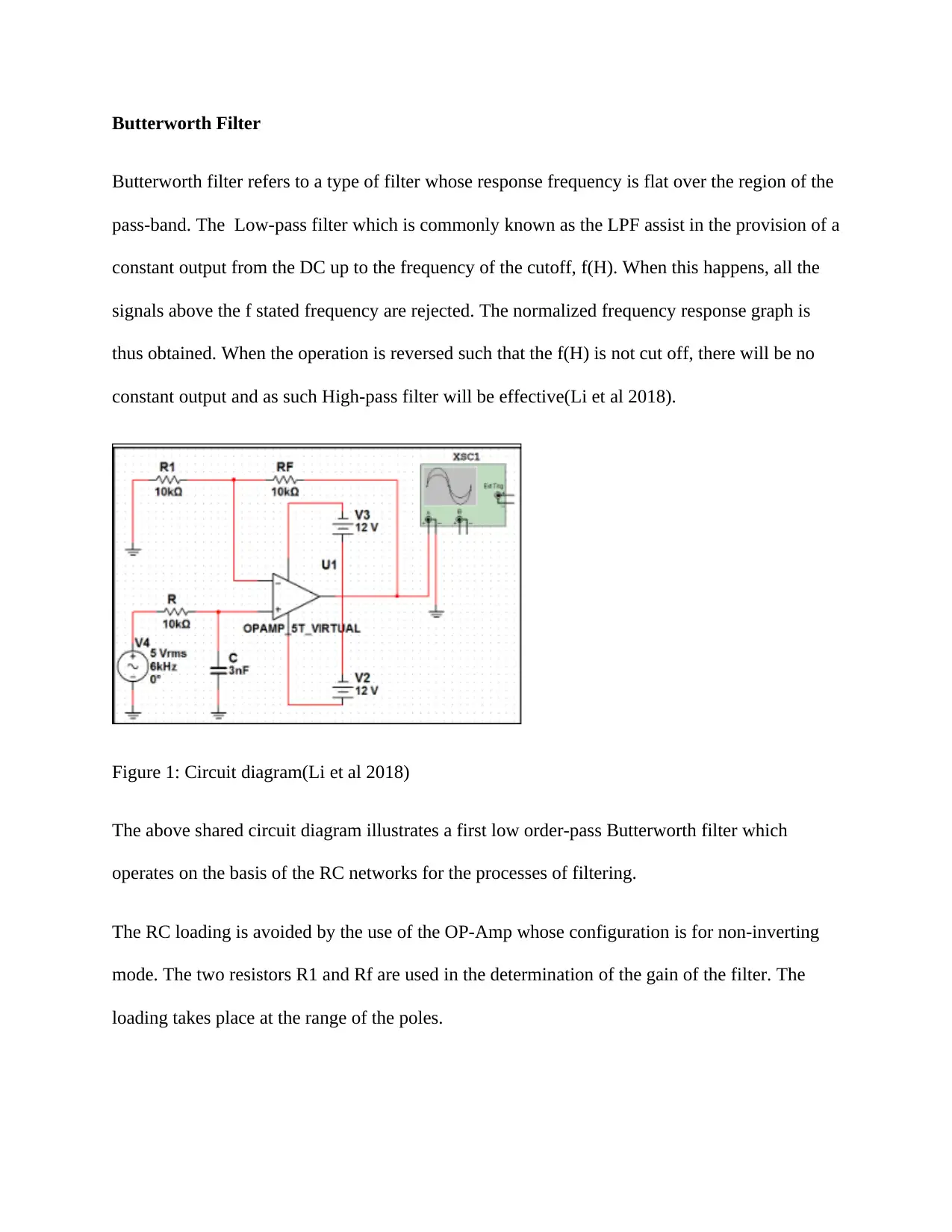
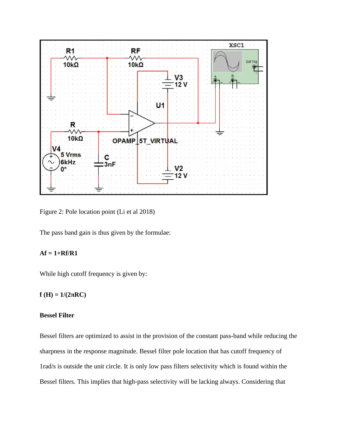
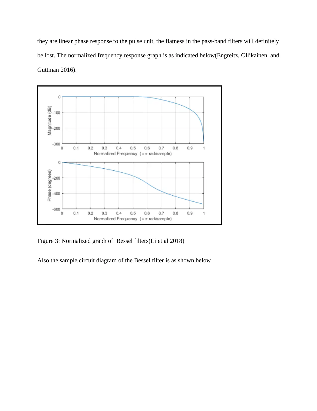
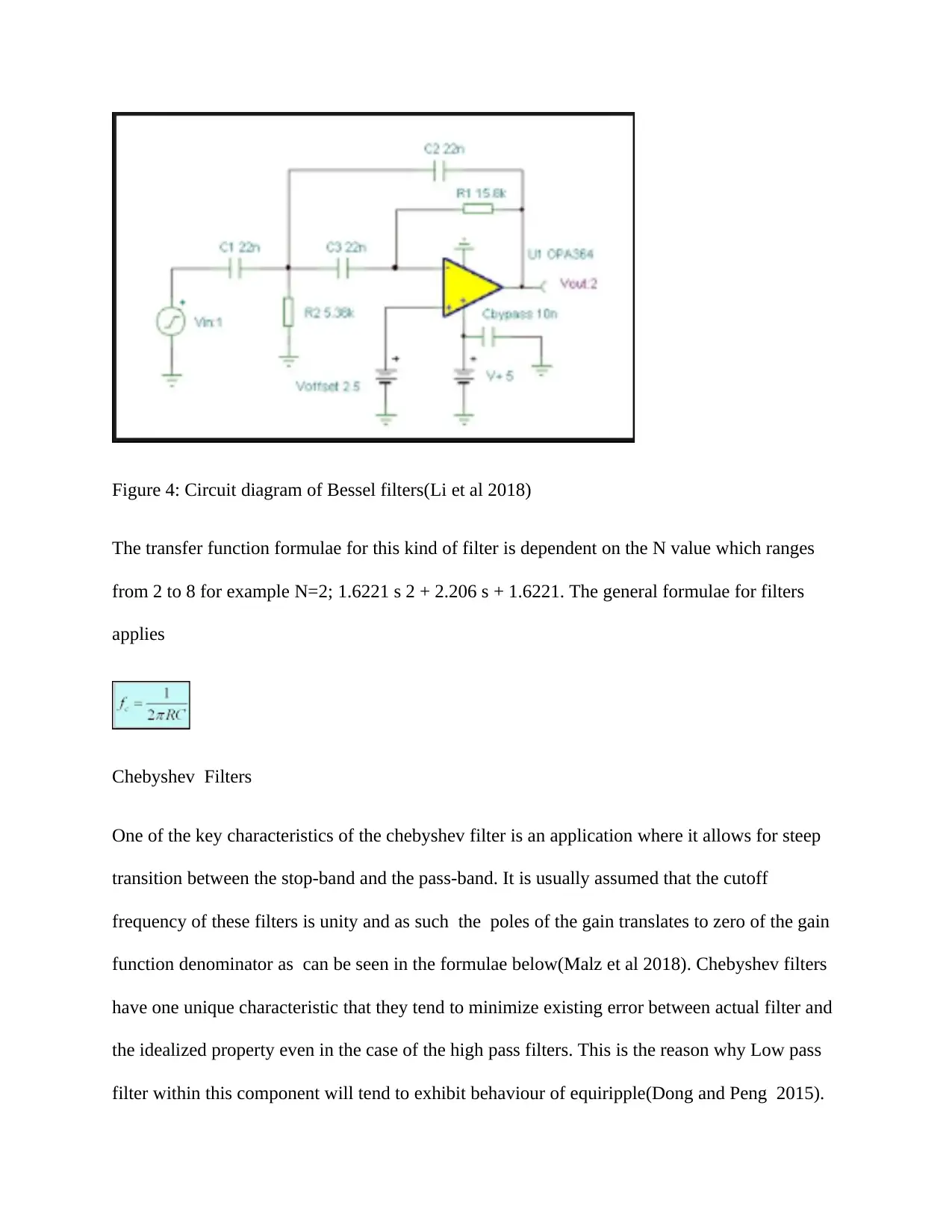
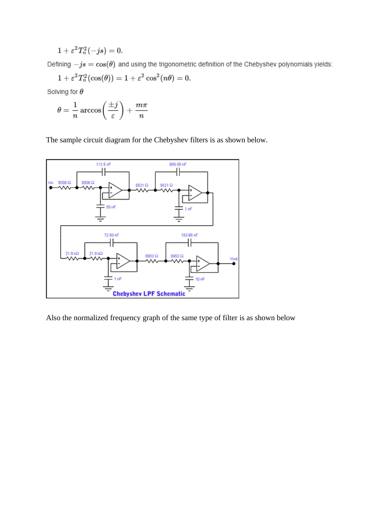
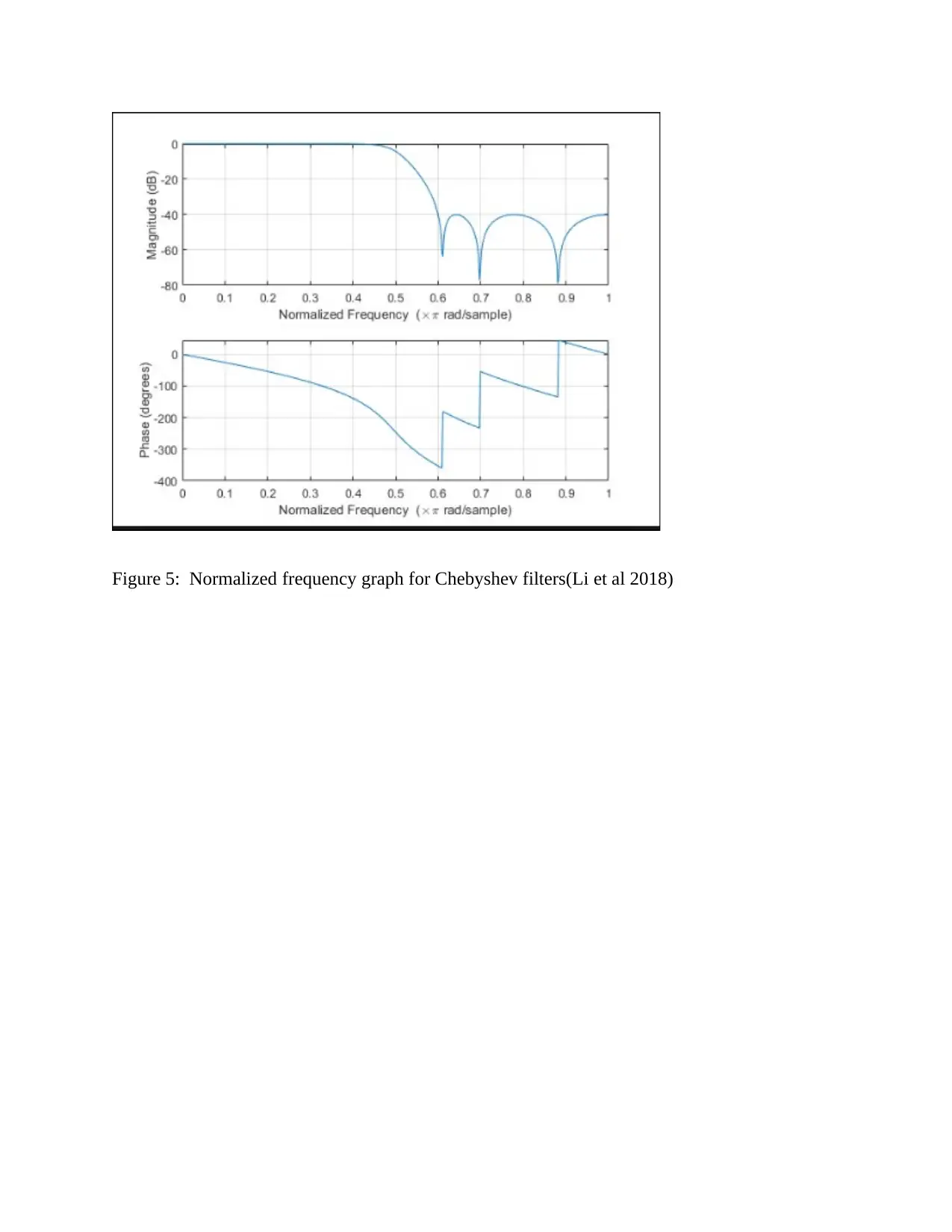
This report delves into the analysis of operational amplifiers (Op-Amps) and their applications in various filter designs. It specifically examines three types of filters: Butterworth, Bessel, and Chebyshev filters. The report begins by defining the characteristics of each filter type, including their frequency response, circuit diagrams, and pole locations. For the Butterworth filter, the report highlights its flat pass-band response and the use of RC networks in its design. The Bessel filter is discussed for its constant pass-band and linear phase response. The Chebyshev filter is analyzed for its steep transition between the stop-band and pass-band. The report includes circuit diagrams and normalized frequency response graphs to illustrate each filter's behavior. The report also provides the relevant formulas, such as the pass-band gain and high cutoff frequency, and includes references to relevant research papers. This document serves as a comprehensive guide to understanding and comparing these essential filter types in electrical engineering.
Document Page
OPERATIONAL AMPLIFIERS
By Name
Course
Instructor
Institution
Location
Date
tabler-icon-diamond-filled.svg

Paraphrase This Document

Need a fresh take? Get an instant paraphrase of this document with our AI Paraphraser
Document Page
Butterworth Filter
Butterworth filter refers to a type of filter whose response frequency is flat over the region of the
pass-band. The Low-pass filter which is commonly known as the LPF assist in the provision of a
constant output from the DC up to the frequency of the cutoff, f(H). When this happens, all the
signals above the f stated frequency are rejected. The normalized frequency response graph is
thus obtained. When the operation is reversed such that the f(H) is not cut off, there will be no
constant output and as such High-pass filter will be effective(Li et al 2018).
Figure 1: Circuit diagram(Li et al 2018)
The above shared circuit diagram illustrates a first low order-pass Butterworth filter which
operates on the basis of the RC networks for the processes of filtering.
The RC loading is avoided by the use of the OP-Amp whose configuration is for non-inverting
mode. The two resistors R1 and Rf are used in the determination of the gain of the filter. The
loading takes place at the range of the poles.
Document Page
Figure 2: Pole location point (Li et al 2018)
The pass band gain is thus given by the formulae:
Af = 1+Rf/R1
While high cutoff frequency is given by:
f (H) = 1/(2πRC)
Bessel Filter
Bessel filters are optimized to assist in the provision of the constant pass-band while reducing the
sharpness in the response magnitude. Bessel filter pole location that has cutoff frequency of
1rad/s is outside the unit circle. It is only low pass filters selectivity which is found within the
Bessel filters. This implies that high-pass selectivity will be lacking always. Considering that
Document Page
they are linear phase response to the pulse unit, the flatness in the pass-band filters will definitely
be lost. The normalized frequency response graph is as indicated below(Engreitz, Ollikainen and
Guttman 2016).
Figure 3: Normalized graph of Bessel filters(Li et al 2018)
Also the sample circuit diagram of the Bessel filter is as shown below
tabler-icon-diamond-filled.svg

Paraphrase This Document

Need a fresh take? Get an instant paraphrase of this document with our AI Paraphraser
Document Page
Figure 4: Circuit diagram of Bessel filters(Li et al 2018)
The transfer function formulae for this kind of filter is dependent on the N value which ranges
from 2 to 8 for example N=2; 1.6221 s 2 + 2.206 s + 1.6221. The general formulae for filters
applies
Chebyshev Filters
One of the key characteristics of the chebyshev filter is an application where it allows for steep
transition between the stop-band and the pass-band. It is usually assumed that the cutoff
frequency of these filters is unity and as such the poles of the gain translates to zero of the gain
function denominator as can be seen in the formulae below(Malz et al 2018). Chebyshev filters
have one unique characteristic that they tend to minimize existing error between actual filter and
the idealized property even in the case of the high pass filters. This is the reason why Low pass
filter within this component will tend to exhibit behaviour of equiripple(Dong and Peng 2015).
Document Page
The sample circuit diagram for the Chebyshev filters is as shown below.
Also the normalized frequency graph of the same type of filter is as shown below
Document Page
Figure 5: Normalized frequency graph for Chebyshev filters(Li et al 2018)
tabler-icon-diamond-filled.svg

Paraphrase This Document

Need a fresh take? Get an instant paraphrase of this document with our AI Paraphraser
Document Page
References
Dong, L. and Peng, X., IMRA America Inc, 2015. Rare earth doped and large effective area
optical fibers for fiber lasers and amplifiers. U.S. Patent 9,151,889.
Engreitz, J.M., Ollikainen, N. and Guttman, M., 2016. Long non-coding RNAs: spatial
amplifiers that control nuclear structure and gene expression. Nature Reviews Molecular Cell
Biology, 17(12), p.756.
Li, J., Rehman, J., Malik, A.B. and Marsboom, G., 2018. Fibroblasts as Disease Amplifiers in
Pulmonary Hypertensive Mice Carrying a BMPR2+/R899X
Mutation. Circulation, 138(Suppl_1), pp.A16444-A16444.
Malz, D., Tóth, L.D., Bernier, N.R., Feofanov, A.K., Kippenberg, T.J. and Nunnenkamp, A.,
2018. Quantum-limited directional amplifiers with optomechanics. Physical review
letters, 120(2), p.023601.
chevron_up_icon
1 out of 8
circle_padding
hide_on_mobile
zoom_out_icon
[object Object]