Retainer Design and Fabrication: CAD/CAM, 3D Printing, and CBCT Data
VerifiedAdded on 2023/04/12
|6
|1503
|221
Practical Assignment
AI Summary
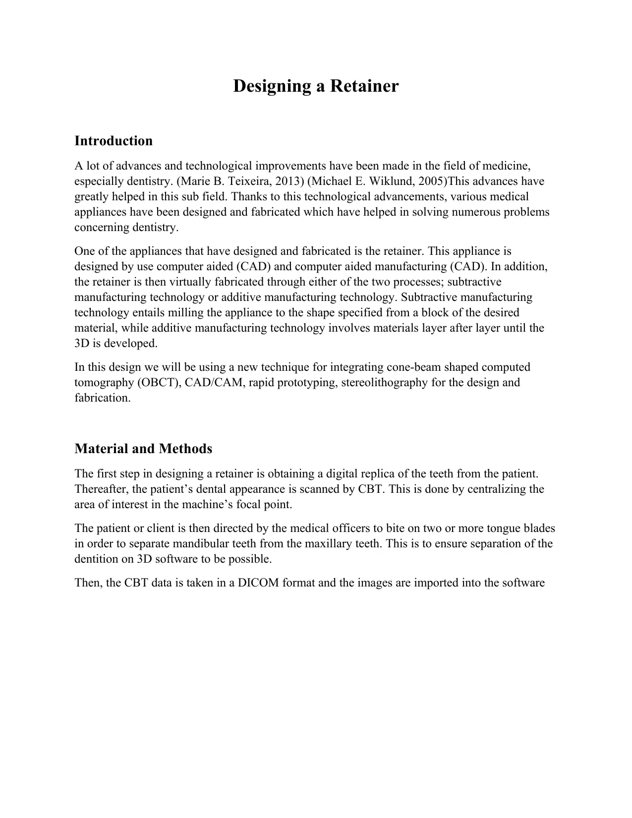
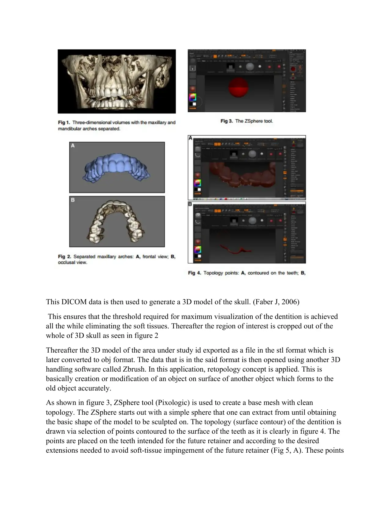
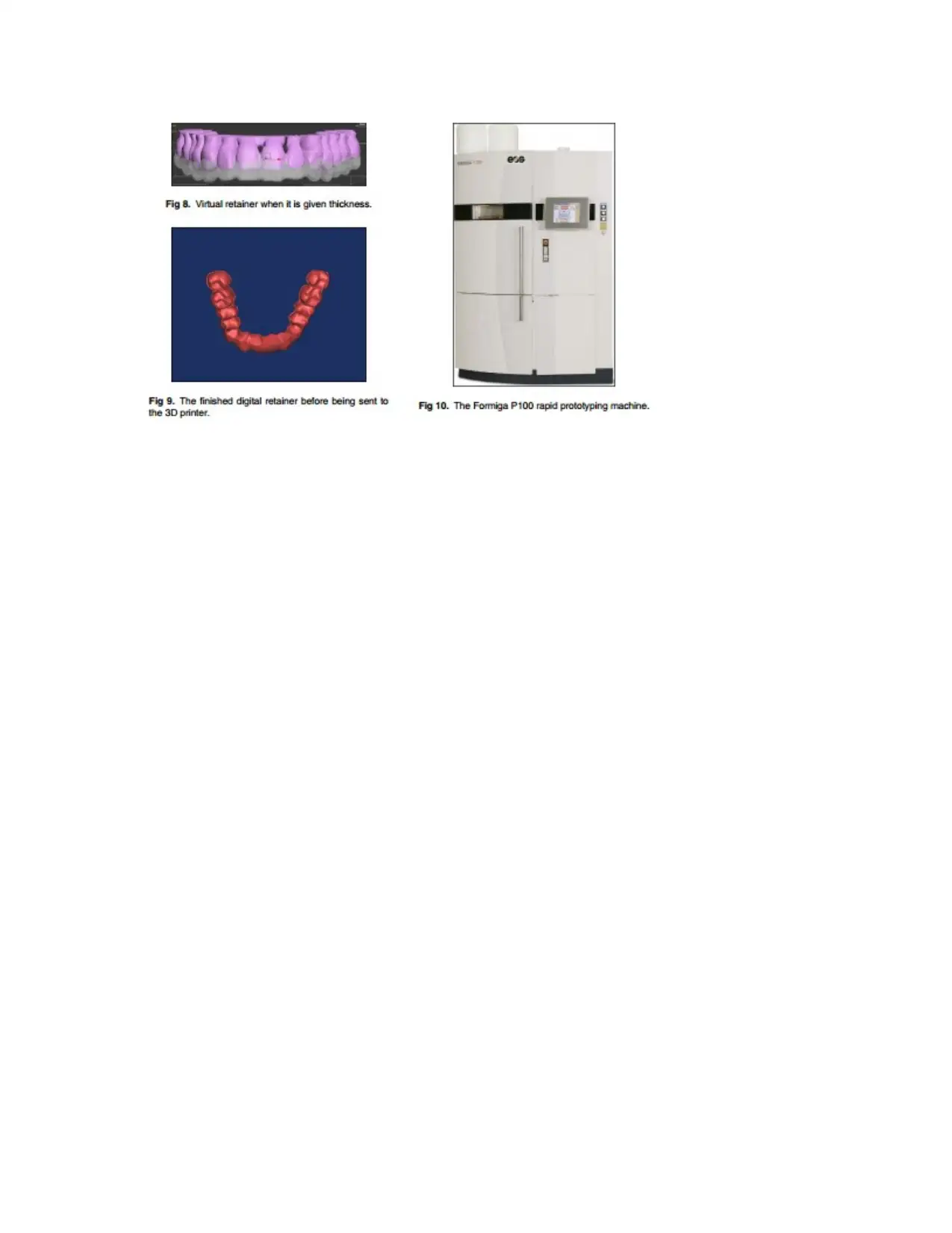
This assignment details a novel technique for designing and fabricating dental retainers, integrating Cone-Beam Computed Tomography (CBCT) data, Computer-Aided Design/Computer-Aided Manufacturing (CAD/CAM), rapid prototyping, and stereolithography. The process begins with obtaining a digital replica of the teeth using CBCT, followed by creating a 3D model and using Zbrush software for retopology and mesh creation. The virtual retainer is then given a thickness and exported as an .stl file for 3D printing using selective laser sintering. The assignment highlights the advantages of this approach, including simplicity, accuracy, and patient satisfaction, paving the way for custom orthodontic appliances in the digital era. The assignment references various sources on the subject. The fabricated retainer is then checked for smooth surfaces and desired extensions. The assignment discusses the integration of these technologies and concludes that this technique is a promising approach to modern dentistry.

Designing a Retainer
Introduction
A lot of advances and technological improvements have been made in the field of medicine,
especially dentistry. (Marie B. Teixeira, 2013) (Michael E. Wiklund, 2005)This advances have
greatly helped in this sub field. Thanks to this technological advancements, various medical
appliances have been designed and fabricated which have helped in solving numerous problems
concerning dentistry.
One of the appliances that have designed and fabricated is the retainer. This appliance is
designed by use computer aided (CAD) and computer aided manufacturing (CAD). In addition,
the retainer is then virtually fabricated through either of the two processes; subtractive
manufacturing technology or additive manufacturing technology. Subtractive manufacturing
technology entails milling the appliance to the shape specified from a block of the desired
material, while additive manufacturing technology involves materials layer after layer until the
3D is developed.
In this design we will be using a new technique for integrating cone-beam shaped computed
tomography (OBCT), CAD/CAM, rapid prototyping, stereolithography for the design and
fabrication.
Material and Methods
The first step in designing a retainer is obtaining a digital replica of the teeth from the patient.
Thereafter, the patient’s dental appearance is scanned by CBT. This is done by centralizing the
area of interest in the machine’s focal point.
The patient or client is then directed by the medical officers to bite on two or more tongue blades
in order to separate mandibular teeth from the maxillary teeth. This is to ensure separation of the
dentition on 3D software to be possible.
Then, the CBT data is taken in a DICOM format and the images are imported into the software
Paraphrase This Document
Need a fresh take? Get an instant paraphrase of this document with our AI Paraphraser

This DICOM data is then used to generate a 3D model of the skull. (Faber J, 2006)
This ensures that the threshold required for maximum visualization of the dentition is achieved
all the while eliminating the soft tissues. Thereafter the region of interest is cropped out of the
whole of 3D skull as seen in figure 2
Thereafter the 3D model of the area under study id exported as a file in the stl format which is
later converted to obj format. The data that is in the said format is then opened using another 3D
handling software called Zbrush. In this application, retopology concept is applied. This is
basically creation or modification of an object on surface of another object which forms to the
old object accurately.
As shown in figure 3, ZSphere tool (Pixologic) is used to create a base mesh with clean
topology. The ZSphere starts out with a simple sphere that one can extract from until obtaining
the basic shape of the model to be sculpted on. The topology (surface contour) of the dentition is
drawn via selection of points contoured to the surface of the teeth as it is clearly in figure 4. The
points are placed on the teeth intended for the future retainer and according to the desired
extensions needed to avoid soft-tissue impingement of the future retainer (Fig 5, A). These points

⊘ This is a preview!⊘
Do you want full access?
Subscribe today to unlock all pages.

Trusted by 1+ million students worldwide

are connected to each other forming polygons (Fig 5, B and C). An important criterion while
placing the points is to preserve the symmetric geometry that allows creating a uniform mesh.
The more symmetric and uniform (rectangular or square) the polygons are, the better the
topology that is created, and the more uniform and accurate the mesh will be. No triangles or
unsymmetrical polygons should be drawn. This topology forms the mesh or framework (Fig 6),
which is the foundation of the future virtual retainer.
The virtual retainer is checked for extensions and uniformity; then an adaptive skin is created
(Fig 7). For more detailing of the mesh, the skin mesh could be divided into more polygons and
projected onto the teeth for better conforming; it is the same concept as increasing the resolution
Paraphrase This Document
Need a fresh take? Get an instant paraphrase of this document with our AI Paraphraser

of a digital picture by doubling the pixels.
The virtual mesh of the future retainer is now created but waiting to be given a thickness. The
current data of the virtual retainer are exported as an .obj format back again to the 3ds Max
software, where it is given a custom thickness (Fig 8). The thickness chosen hereby is 0.7 mm.
In this instance, the virtual retainer could be exported as an .stl file (Fig 9). The extension “.stl”
is said to be derived from “stereolithography or surface tessellation language.” An .stl file is a
format used by stereolithography software to generate information needed to produce 3D models
on stereolithography machines by rapid prototyping processes. Most CAD vendors provide
an .stl output format for CAM. It is a triangular representation of a 3D surface geometry. The
surface is tessellated, or broken down logically into a series of small triangles.
Each triangle is described by a perpendicular direction and 3 points representing the vertices
(corners) of the triangle. These data are used by a slicing algorithm to determine the cross section
of the 3D shape to be built by the rapid prototyping machine; .stl files describe only the surface
geometry of a 3D object without any representation of color, texture, or other common CAD
model attributes.
The .stl file is sent to the 3D printer rapid prototyping machine (Formiga P100; EOS, Munich,
Germany) (Fig 10). This 3D printer is a selective laser sintering machine. The selective laser
sintering process uses a high power laser to fuse fine powder particles of the material.
The platform on which the part is being built rises, and a new layer of powder (particles) is
applied. Thus, the object is selectively hardened (grows) layer by layer. At the end, the hardened
part is lifted out of the remaining powder, which acts as a support.
The material used is called Fine Polyamide PA 2200 (EOS). It is white and feels powdery to the
touch. The material melts at 80C and consists of spherical powder that has an average grain size
of 60 mm. The term “polyamide” might not be well known, but nylon is a rather common hard
polyamide.
An advantage of this 3D printer is the simple and quick removal of the support material
compared with other processes. For delicate parts, compressed air is used to blow away the
powder. The laser requires some time to warm up. After the retainer is fabricated simply taken
out and checked that the smooth surfaces conform to the teeth with the extensions as designed
on the 3D software. The retainer is constructed from the white material (Fig 11). However, this
technique is applicable to analogous 3D printers and transparent material.
After the retainer is fabricated, it can be checked on the patient's physical dental model and
finally in the patient's mouth. It should have smooth surfaces that conform to the teeth and the
desired extensions as designed on the 3D software. The retainer's edges and corners should be
away from the patient's soft tissue, with no sharp edges.
Discussion
This technique integrates the CBCT data, CAD/CAM, rapid prototyping, and additive
manufacturing stereolithographic technologies in orthodontics. The accuracy of 3D scanning
systems and the manufacturing techniques have proved to be reliable technologies for the
future. They allow custom appliances to be fabricated as designed exactly by the orthodontist.
Unlike the previous attempts that used an expensive laser scanner for digitization of the patient's
dental tissues, the simplicity of this technique is derived from the routine use of CBCT data at a

reasonable cost. (Geckler, 2017) Moreover, the retainer used in this study can be virtually
designed with a regular computer mouse and software that are commercially available instead of
sophisticated and
expensive devices such as the phantom arm.
The patient's digital data are stored in a more convenient way and can be easily sent to any
laboratory or an in-office machine, allowing the practitioner or the technician to fabricate
appliances directly on the patient's digital models obtained by a simple scan. This rapid
prototyping additive manufacturing technique might be expensive and not feasible for everyone
now, but it gives us an idea of how dental appliances could be fabricated in the future. The
material for the retainer used in this attempt was white. This technique could be done using
another 3D printer and other kinds of transparent material.
Conclusions
This article shows the great possibilities of integrating CBCT data, CAD/CAM technology, and
3D printing. Fabricating a 3D virtual retainer with user-friendly software is a promising
technique that could change the way we practice dentistry today. It provides simplicity, speed,
accuracy, and patient satisfaction. This paves the road for designing and manufacturing custom
orthodontic appliances compatible to the new digital orthodontic era.
References
Faber J, P. B. M. Q., 2006. Rapid Prototyping as a tool for Diagnosis and treatment olanning for maxillary
canine imapction. In: J. Orthod, ed. Dentofacial Orthop. london: Springer, pp. 129-583.
Geckler, V., 2017. DESIGN CONTROLS,RISK MANAGEMENT AND PROCESS VALIDATION.... NEW YORK:
wasatch consulting resources LLC.
Marie B. Teixeira, R. B., 2013. Design Controls for medical device industry. 2nd ed. London: CRC press.
Michael E. Wiklund, S. B. W., 2005. Designing usabilty into medical records. london: CRC Press.
⊘ This is a preview!⊘
Do you want full access?
Subscribe today to unlock all pages.

Trusted by 1+ million students worldwide
1 out of 6
Your All-in-One AI-Powered Toolkit for Academic Success.
+13062052269
info@desklib.com
Available 24*7 on WhatsApp / Email
Unlock your academic potential
Copyright © 2020–2025 A2Z Services. All Rights Reserved. Developed and managed by ZUCOL.
