Car Factory Pattern Creation: UML Diagram and C++ Code Analysis Report
VerifiedAdded on 2022/08/21
|8
|1233
|13
Report
AI Summary
This report provides a comprehensive analysis of a car factory using UML diagrams and C++ code. It begins with an introduction to UML diagrams, their uses, and the tools available for creating them. A car factory case study is then presented, detailing the creation of a UML class diagram to represent the system's structure. The report explains the 'Forward Design' process, where the diagram precedes the code, and the 'Backward Design' approach. The diagram illustrates the interactions between different components, such as electric and gas car factories, engines, and doors. Following the diagram, the report provides C++ code implementations for the car factory pattern, including the main class, superclasses for car factories, doors, and engines, and the output. The conclusion emphasizes the importance of UML diagrams in visualizing complex systems, making them easier to understand and simulate. The report also includes references to relevant academic sources.

Car Factory Pattern Creation
Name of the Student
Name of the University
Author Note
Introduction
A Unified Modeling Language (UML) diagram can be used to model a business
process modeling technique. In this paper you will learn about the various use of UML
diagrams and the tools that are used to draw the same. A case study of a car factory is taken
into as an example to get a clear idea about creating and using a UML diagram of the same
(car factory case study) (Afanasyev et al., 2015). After creation of the required UML
Paraphrase This Document
Need a fresh take? Get an instant paraphrase of this document with our AI Paraphraser
diagram, the full car factory scenario will be coded using C++ programming language to get
a clear idea about the working structure of the case study.
Discussion
A UML is used to visually represent a functioning (working) structure of a system.
The structure includes various actors interacting with the system. It will give a better idea
about how the system works. In the end, coding of the same is done to obtain the working
version of the system on a software base. The process of drawing the diagram before and
implementing the code based on the diagram afterward is known as ‘Forward Design.’ In the
case of ‘Backward Design,’ the same things are done in reverse direction i.e., first the coding
part is done, and then UML diagrams are drawn in documentation format. It also includes the
actors interacting with the system (Nishi, 2015).
Various tools like AgroUML, Gliffy, Microsoft Visio, Lucidchart, Magic Draw, and
many more can be used to draw UML diagrams (Thong & Ameedeen, 2019). Microsoft Visio
(MS Visio) will be used for drawing the UML diagram because of the simplicity of the
application software and easy understanding. MS Visio is one of the most used and popular
visualization and chart making software. It is mainly used to draw and visualize various
proprietary diagrams. Platforms like browsers, windows, iPad app, and virtual machines are
supported by it along with programming languages like C#, C++, VSDM, and VSDX.
Subscription of the same (MSVisio) can vary from $18/month to $590 a year (for
Professional version).
The following case study of an abstract factory pattern will give a clear idea about
how MS Visio can be used to analyze the car factory parts/tasks. It will depict the interaction
and relation between each part of the car factory. You will also get an understanding about
the client’s interaction with the system. The diagram will have a separate entity for each
functioning part of the case study.
Case Study
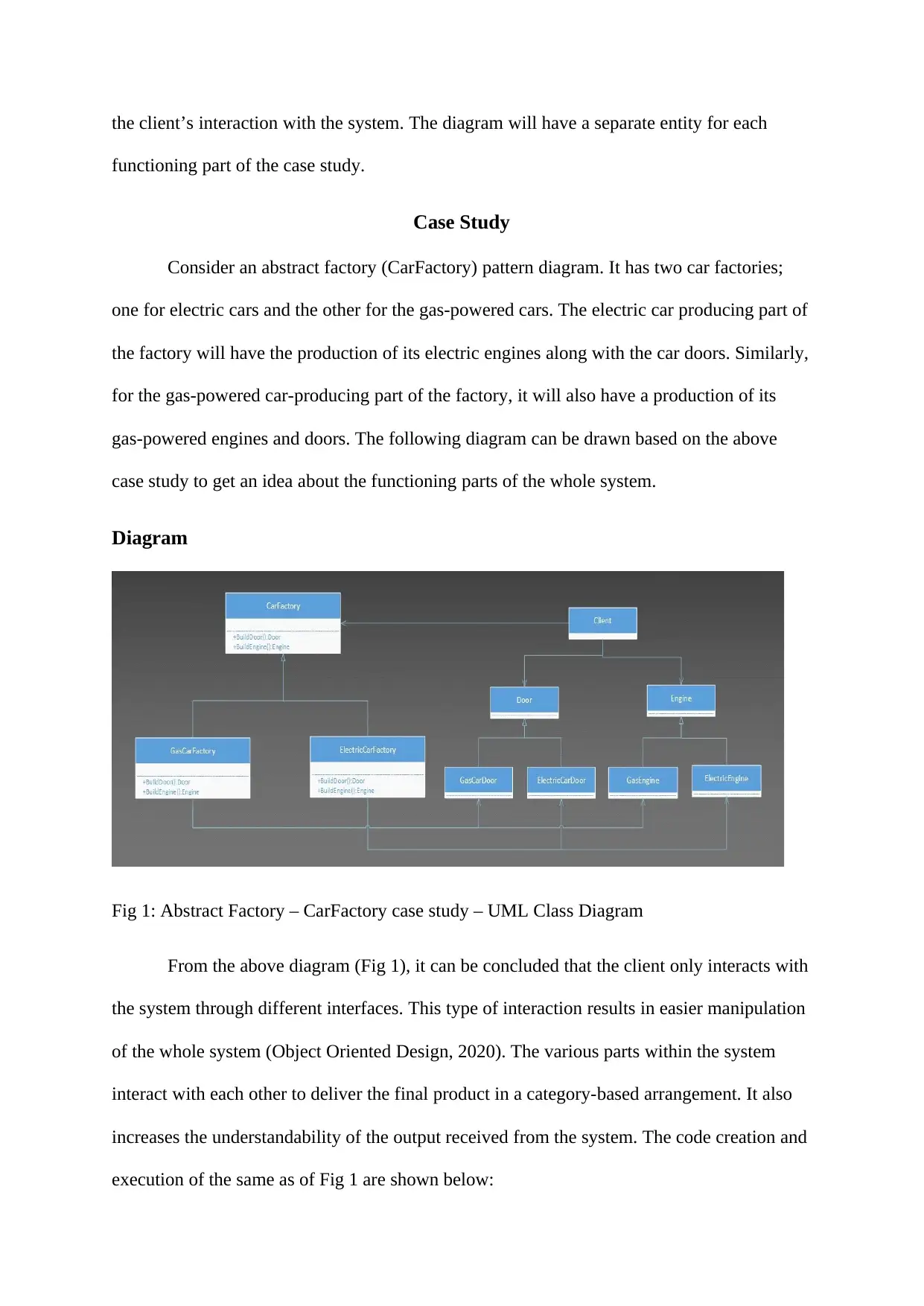
Consider an abstract factory (CarFactory) pattern diagram. It has two car factories;
one for electric cars and the other for the gas-powered cars. The electric car producing part of
the factory will have the production of its electric engines along with the car doors. Similarly,
for the gas-powered car-producing part of the factory, it will also have a production of its
gas-powered engines and doors. The following diagram can be drawn based on the above
case study to get an idea about the functioning parts of the whole system.
Diagram
Fig 1: Abstract Factory – CarFactory case study – UML Class Diagram
From the above diagram (Fig 1), it can be concluded that the client only interacts with
the system through different interfaces. This type of interaction results in easier manipulation
of the whole system (Object Oriented Design, 2020). The various parts within the system
interact with each other to deliver the final product in a category-based arrangement. It also
increases the understandability of the output received from the system. The code creation and
execution of the same as of Fig 1 are shown below:
⊘ This is a preview!⊘
Do you want full access?
Subscribe today to unlock all pages.

Trusted by 1+ million students worldwide
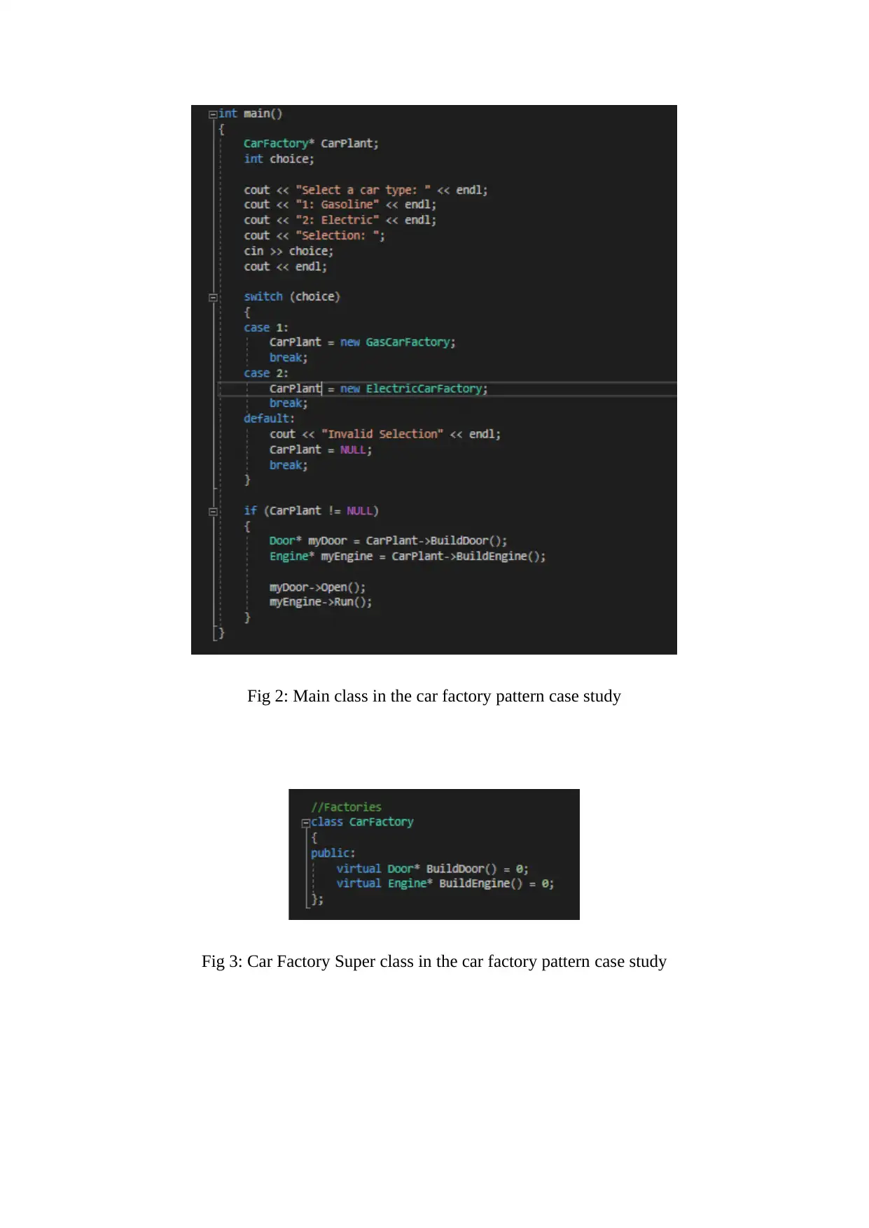
Fig 2: Main class in the car factory pattern case study
Fig 3: Car Factory Super class in the car factory pattern case study
Fig 3: Car Factory Super class in the car factory pattern case study
Paraphrase This Document
Need a fresh take? Get an instant paraphrase of this document with our AI Paraphraser
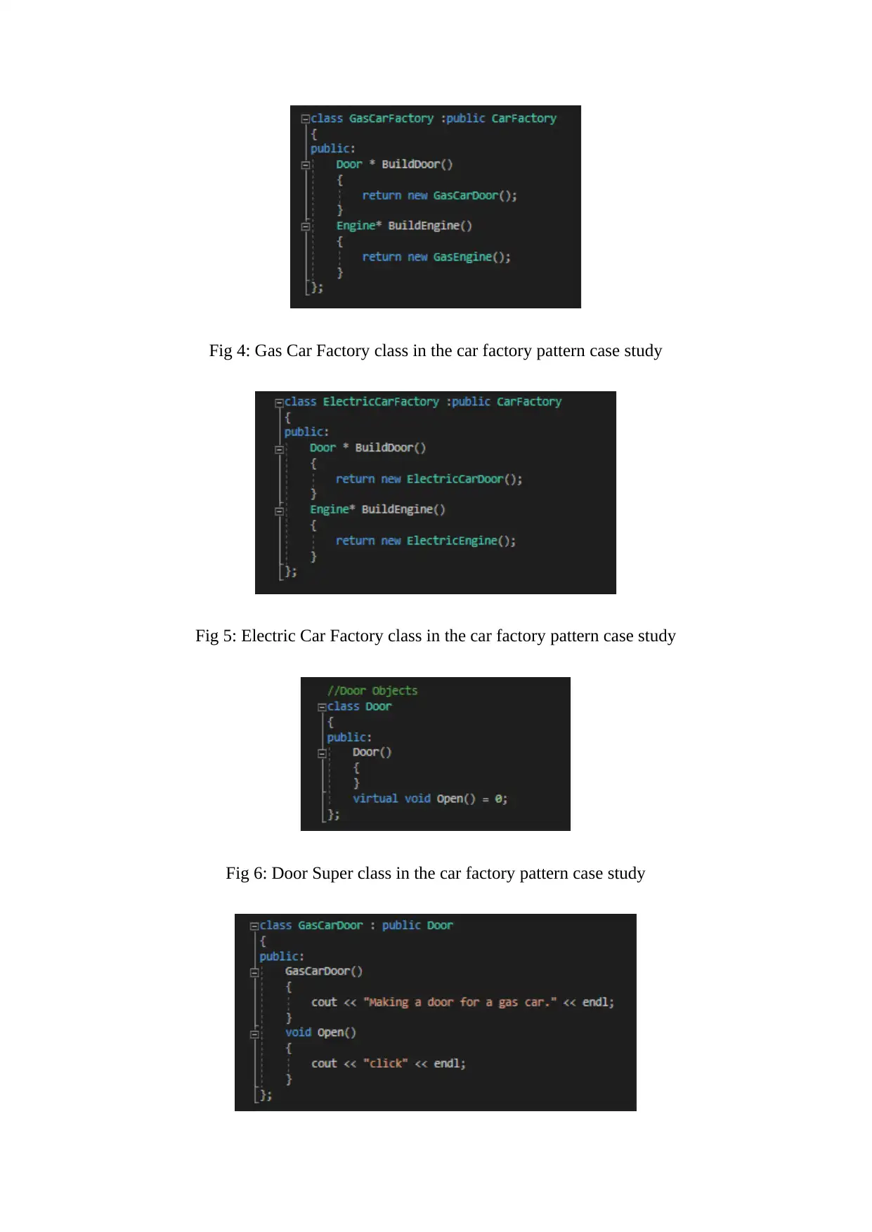
Fig 4: Gas Car Factory class in the car factory pattern case study
Fig 5: Electric Car Factory class in the car factory pattern case study
Fig 6: Door Super class in the car factory pattern case study
Fig 5: Electric Car Factory class in the car factory pattern case study
Fig 6: Door Super class in the car factory pattern case study
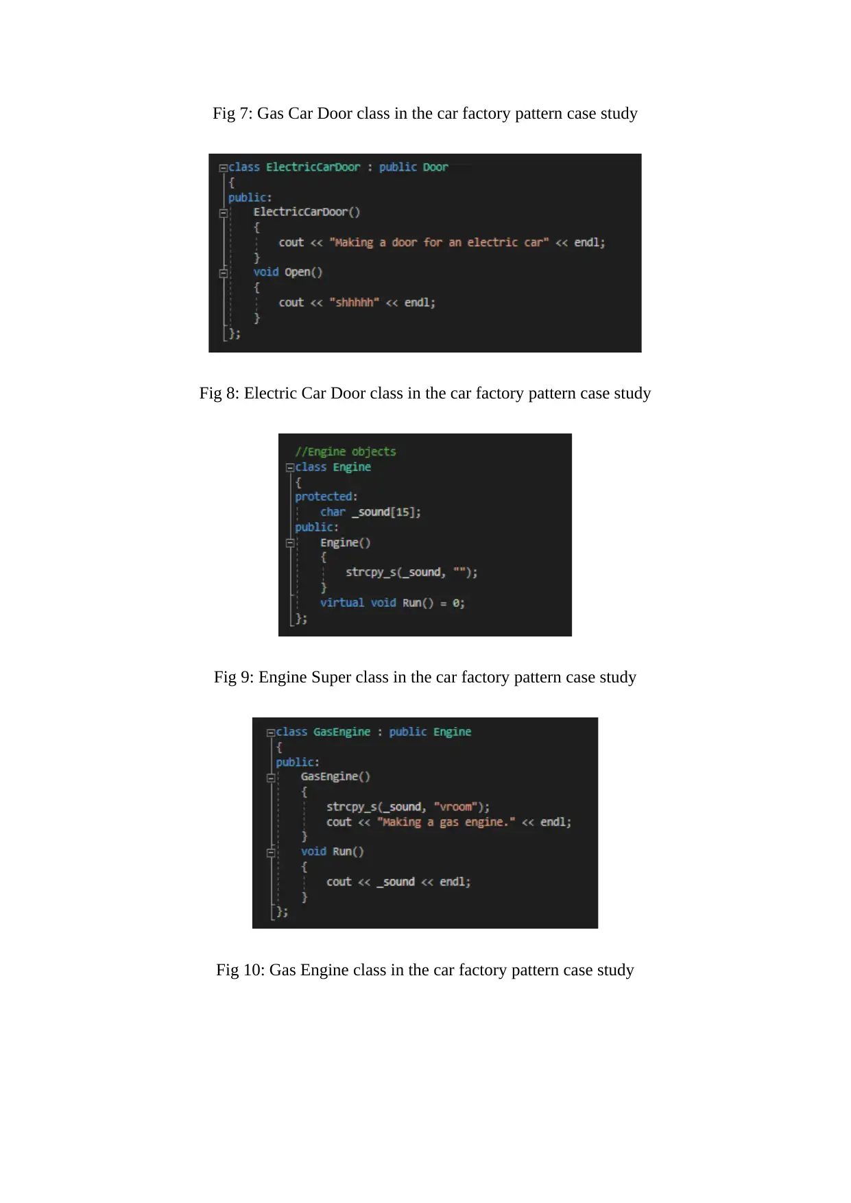
Fig 7: Gas Car Door class in the car factory pattern case study
Fig 8: Electric Car Door class in the car factory pattern case study
Fig 9: Engine Super class in the car factory pattern case study
Fig 10: Gas Engine class in the car factory pattern case study
Fig 8: Electric Car Door class in the car factory pattern case study
Fig 9: Engine Super class in the car factory pattern case study
Fig 10: Gas Engine class in the car factory pattern case study
⊘ This is a preview!⊘
Do you want full access?
Subscribe today to unlock all pages.

Trusted by 1+ million students worldwide
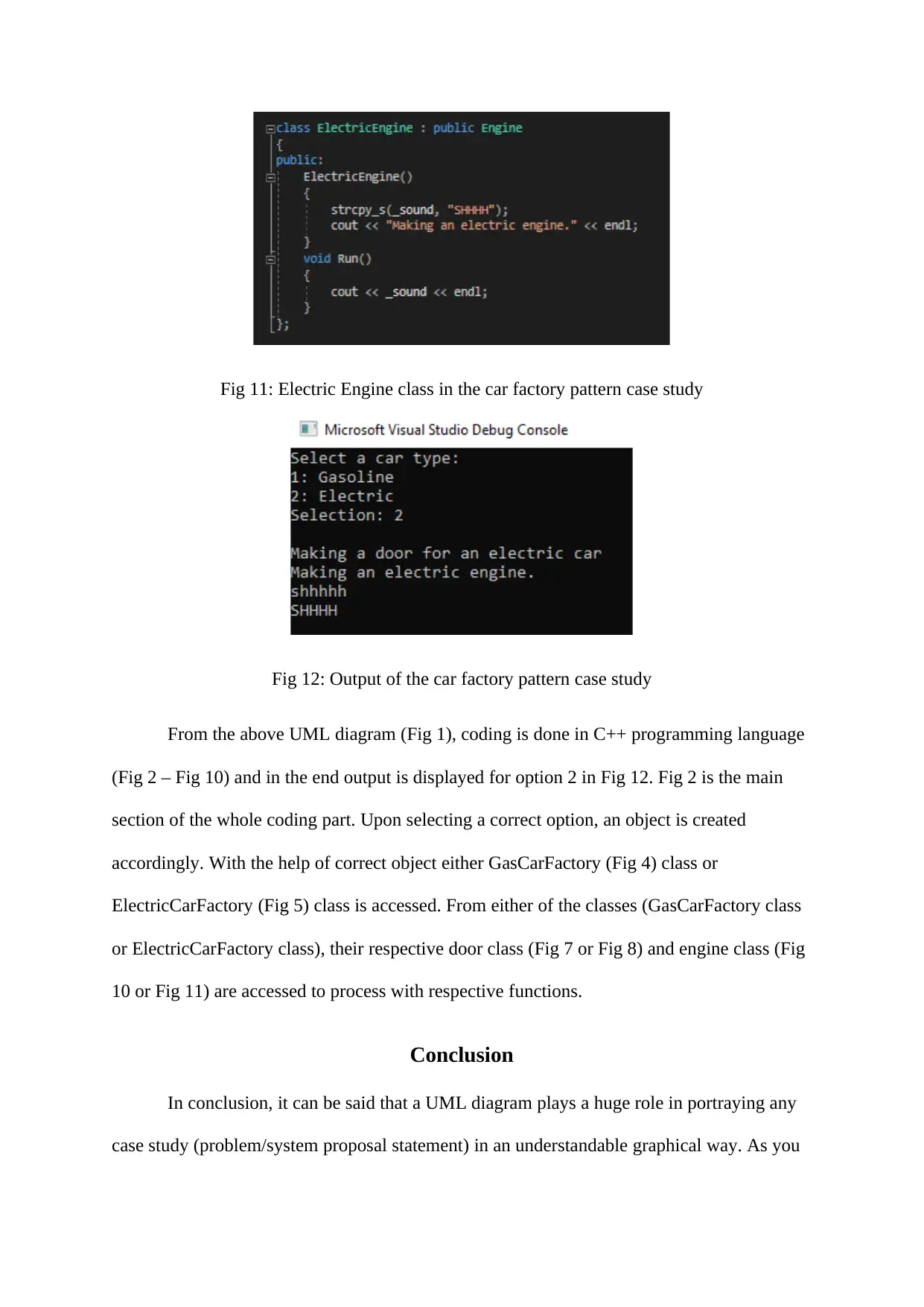
Fig 11: Electric Engine class in the car factory pattern case study
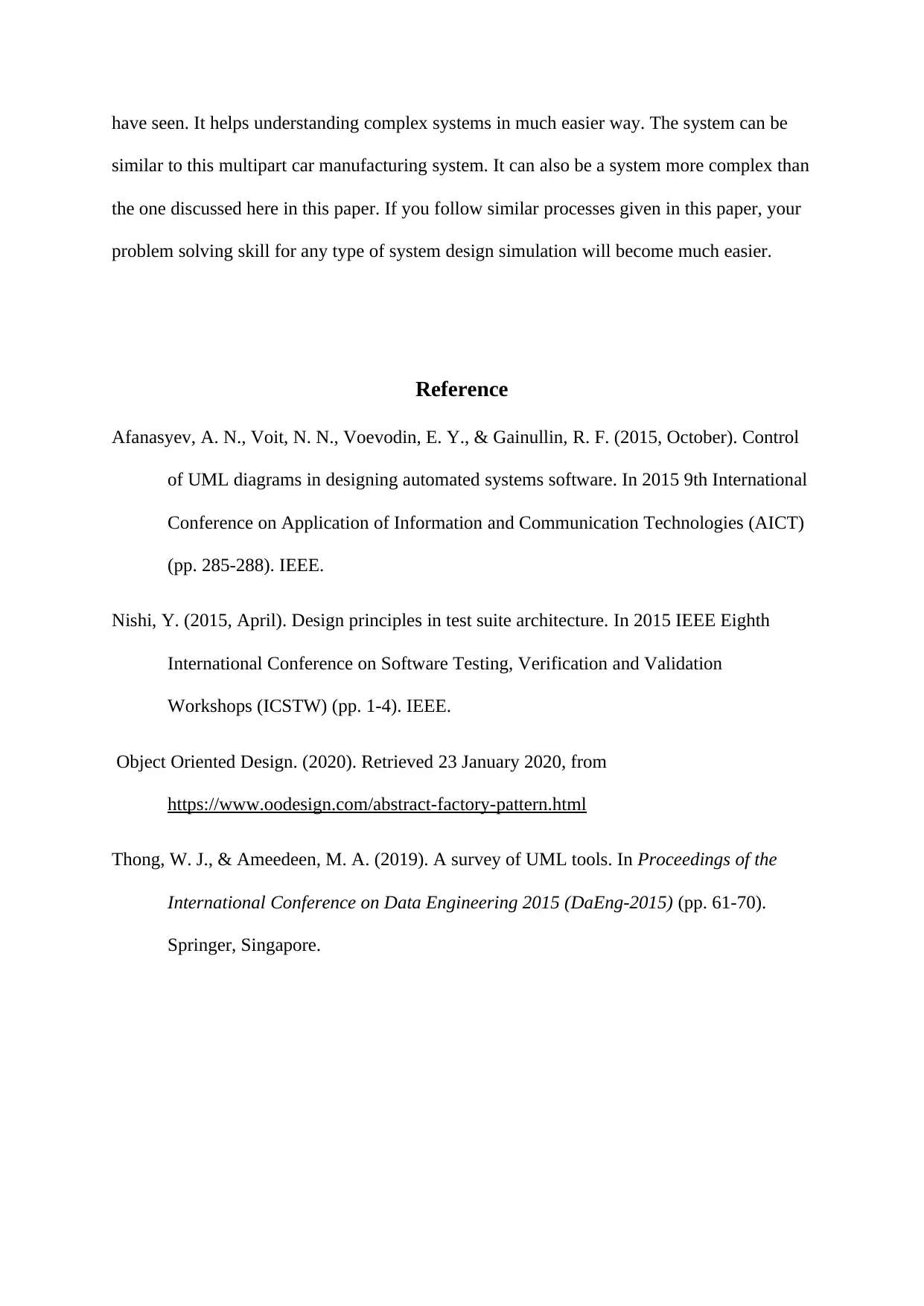
Fig 12: Output of the car factory pattern case study
From the above UML diagram (Fig 1), coding is done in C++ programming language
(Fig 2 – Fig 10) and in the end output is displayed for option 2 in Fig 12. Fig 2 is the main
section of the whole coding part. Upon selecting a correct option, an object is created
accordingly. With the help of correct object either GasCarFactory (Fig 4) class or
ElectricCarFactory (Fig 5) class is accessed. From either of the classes (GasCarFactory class
or ElectricCarFactory class), their respective door class (Fig 7 or Fig 8) and engine class (Fig
10 or Fig 11) are accessed to process with respective functions.
Conclusion
In conclusion, it can be said that a UML diagram plays a huge role in portraying any
case study (problem/system proposal statement) in an understandable graphical way. As you
Paraphrase This Document
Need a fresh take? Get an instant paraphrase of this document with our AI Paraphraser
have seen. It helps understanding complex systems in much easier way. The system can be
similar to this multipart car manufacturing system. It can also be a system more complex than
the one discussed here in this paper. If you follow similar processes given in this paper, your
problem solving skill for any type of system design simulation will become much easier.
Reference
Afanasyev, A. N., Voit, N. N., Voevodin, E. Y., & Gainullin, R. F. (2015, October). Control
of UML diagrams in designing automated systems software. In 2015 9th International
Conference on Application of Information and Communication Technologies (AICT)
(pp. 285-288). IEEE.
Nishi, Y. (2015, April). Design principles in test suite architecture. In 2015 IEEE Eighth
International Conference on Software Testing, Verification and Validation
Workshops (ICSTW) (pp. 1-4). IEEE.
Object Oriented Design. (2020). Retrieved 23 January 2020, from
https://www.oodesign.com/abstract-factory-pattern.html
Thong, W. J., & Ameedeen, M. A. (2019). A survey of UML tools. In Proceedings of the
International Conference on Data Engineering 2015 (DaEng-2015) (pp. 61-70).
Springer, Singapore.
1 out of 8
Related Documents
Your All-in-One AI-Powered Toolkit for Academic Success.
+13062052269
info@desklib.com
Available 24*7 on WhatsApp / Email
![[object Object]](/_next/static/media/star-bottom.7253800d.svg)
Unlock your academic potential
Copyright © 2020–2026 A2Z Services. All Rights Reserved. Developed and managed by ZUCOL.


