Report on Collin's Car Park System Design and Requirements
VerifiedAdded on 2021/05/31
|10
|2285
|71
Report
AI Summary
This report outlines the design and requirements for Collin's car park system, covering both functional and non-functional aspects. The report begins with a detailed requirements specification, identifying how different user types (ordinary customers, fixed customers, and security personnel) interact with the system. It defines user inputs, expected results, and system behaviors for various scenarios, such as entering and exiting the car park, paying for tickets, and managing subscriptions. The report then moves on to use case modeling, presenting a use case diagram and detailed descriptions for each use case, clarifying the system's interactions with its users. A class diagram is included to illustrate the system's structural model, followed by a discussion of the software development life cycle (SDLC) stages applicable to the project. Assumptions related to fixed customer subscriptions are also described. The report provides a comprehensive overview of the system's design and requirements, offering valuable insights into its functionality and operation.

COVER PAGE
Paraphrase This Document
Need a fresh take? Get an instant paraphrase of this document with our AI Paraphraser
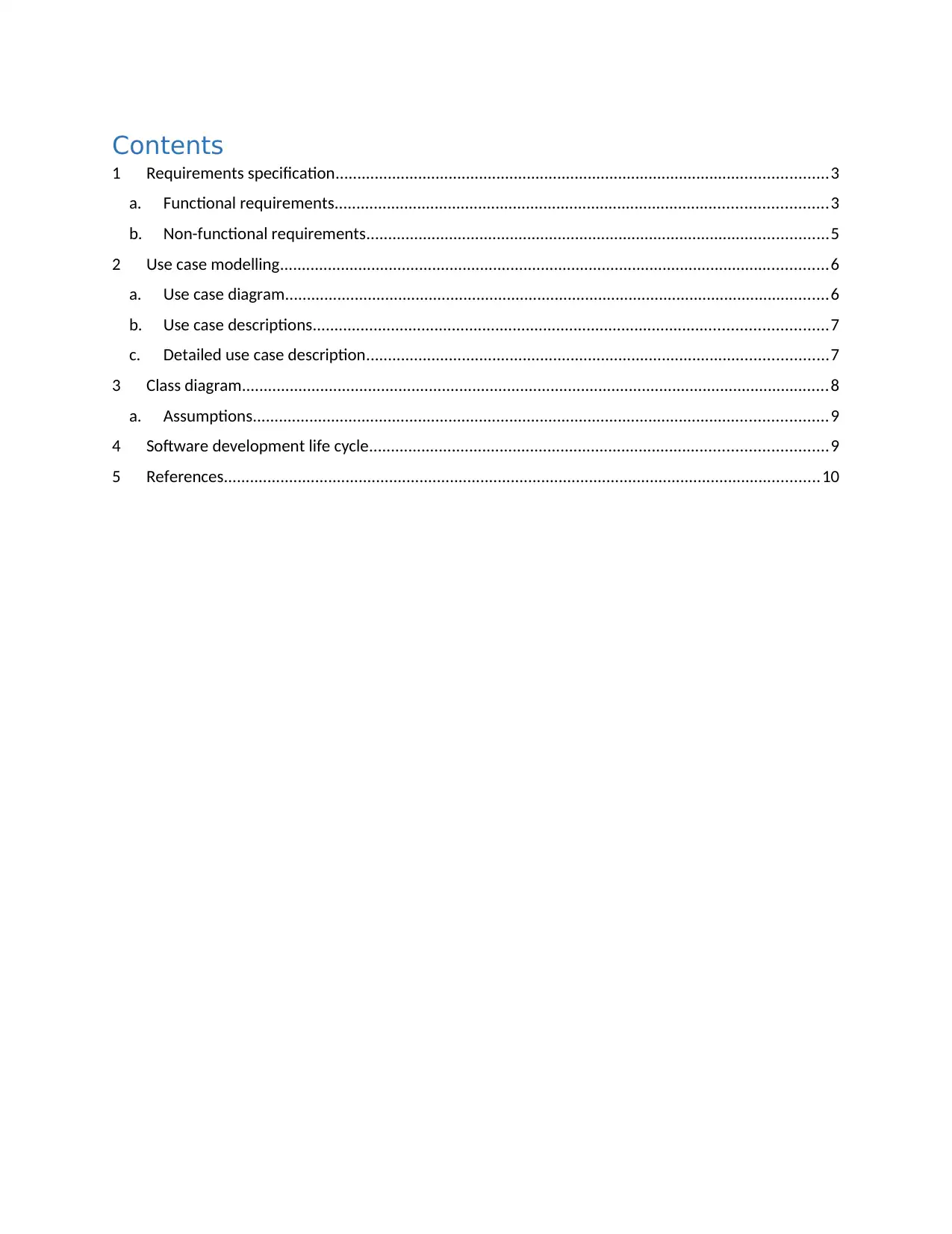
Contents
1 Requirements specification.................................................................................................................3
a. Functional requirements.................................................................................................................3
b. Non-functional requirements..........................................................................................................5
2 Use case modelling..............................................................................................................................6
a. Use case diagram.............................................................................................................................6
b. Use case descriptions......................................................................................................................7
c. Detailed use case description..........................................................................................................7
3 Class diagram.......................................................................................................................................8
a. Assumptions....................................................................................................................................9
4 Software development life cycle.........................................................................................................9
5 References.........................................................................................................................................10
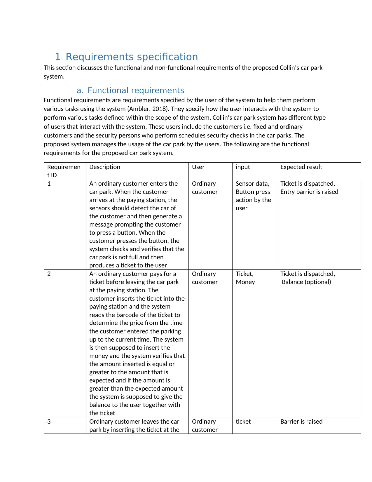
1 Requirements specification
This section discusses the functional and non-functional requirements of the proposed Collin’s car park
system.
a. Functional requirements
Functional requirements are requirements specified by the user of the system to help them perform
various tasks using the system (Ambler, 2018). They specify how the user interacts with the system to
perform various tasks defined within the scope of the system. Collin’s car park system has different type
of users that interact with the system. These users include the customers i.e. fixed and ordinary
customers and the security persons who perform schedules security checks in the car parks. The
proposed system manages the usage of the car park by the users. The following are the functional
requirements for the proposed car park system.
Requiremen
t ID
Description User input Expected result
1 An ordinary customer enters the
car park. When the customer
arrives at the paying station, the
sensors should detect the car of
the customer and then generate a
message prompting the customer
to press a button. When the
customer presses the button, the
system checks and verifies that the
car park is not full and then
produces a ticket to the user
Ordinary
customer
Sensor data,
Button press
action by the
user
Ticket is dispatched,
Entry barrier is raised
2 An ordinary customer pays for a
ticket before leaving the car park
at the paying station. The
customer inserts the ticket into the
paying station and the system
reads the barcode of the ticket to
determine the price from the time
the customer entered the parking
up to the current time. The system
is then supposed to insert the
money and the system verifies that
the amount inserted is equal or
greater to the amount that is
expected and if the amount is
greater than the expected amount
the system is supposed to give the
balance to the user together with
the ticket
Ordinary
customer
Ticket,
Money
Ticket is dispatched,
Balance (optional)
3 Ordinary customer leaves the car
park by inserting the ticket at the
Ordinary
customer
ticket Barrier is raised
⊘ This is a preview!⊘
Do you want full access?
Subscribe today to unlock all pages.
Trusted by 1+ million students worldwide
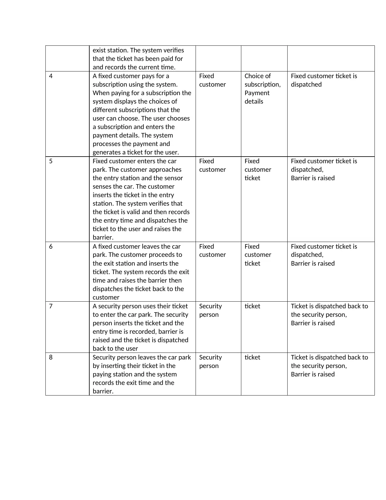
exist station. The system verifies
that the ticket has been paid for
and records the current time.
4 A fixed customer pays for a
subscription using the system.
When paying for a subscription the
system displays the choices of
different subscriptions that the
user can choose. The user chooses
a subscription and enters the
payment details. The system
processes the payment and
generates a ticket for the user.
Fixed
customer
Choice of
subscription,
Payment
details
Fixed customer ticket is
dispatched
5 Fixed customer enters the car
park. The customer approaches
the entry station and the sensor
senses the car. The customer
inserts the ticket in the entry
station. The system verifies that
the ticket is valid and then records
the entry time and dispatches the
ticket to the user and raises the
barrier.
Fixed
customer
Fixed
customer
ticket
Fixed customer ticket is
dispatched,
Barrier is raised
6 A fixed customer leaves the car
park. The customer proceeds to
the exit station and inserts the
ticket. The system records the exit
time and raises the barrier then
dispatches the ticket back to the
customer
Fixed
customer
Fixed
customer
ticket
Fixed customer ticket is
dispatched,
Barrier is raised
7 A security person uses their ticket
to enter the car park. The security
person inserts the ticket and the
entry time is recorded, barrier is
raised and the ticket is dispatched
back to the user
Security
person
ticket Ticket is dispatched back to
the security person,
Barrier is raised
8 Security person leaves the car park
by inserting their ticket in the
paying station and the system
records the exit time and the
barrier.
Security
person
ticket Ticket is dispatched back to
the security person,
Barrier is raised
Paraphrase This Document
Need a fresh take? Get an instant paraphrase of this document with our AI Paraphraser
b. Non-functional requirements
Non-functional requirements are requirements that are used to specify the criteria on which the
operation of a system is judged. Functional requirements specify the behavior of a system and what is
expected of the system while non-functional requirements are specify how the system should perform
the functional requirements (Labunisky, 2017). The following are the functional requirements for the
proposed Collin’s Car park System.
1. Security- Considering the nature of the proposed system, this is perhaps one of the most crucial
non-functional requirement. The proposed system should be able to ensure security at very
many levels. These levels are;
The system should ensure that no unauthorized entry into the car park should
happen. The system should be developed to make sure that all types of entries
i.e. entry for an ordinary customer, fixed customer or security personnel should
happen as expected for all types of users.
The system should make sure the customer is secure from malicious users who
might use it for their malicious gains. This can be done by encrypting the data
before storing it.
2. Performance- The system should perform all actions using the least amount of time to make
sure that the users are able to perform their actions effectively. The response time should be
fast for example when a customer approaches the entry station, the sensors should send the
data and the system should display the message within 3 seconds. When the user inserts the
ticket at the time of exit, the system should not take more than 5 seconds before raising the
barrier. This will help reduce congestion both at the entry station and the exit station.
3. Availability- Availability of the system is crucial as the system is expected to be operational at all
times to make sure users are able to perform all user actions using the system. A user should be
able to enter and leave the car park at any time and this is possible only if the system is available
and operational at all times.
4. Fault tolerance- fault tolerance of a system is the ability of a system to remain operational after
encountering an error. An error in one part of the system should not cause a complete failure of
the system. The system should be designed in such a way that if a fault occurs at the entry sub
system of the system, the exit subsystem and the payment subsystems should continue
operations to ensure that not all actions of the car park are sabotaged. This non-functional
requirement should be looked at carefully during the testing of the system as it has potential to
cause problems to the company if the system is not designed correctly.
5. Recoverability- Recoverability of a system is the ability of a system to restore to normal
functioning by retaining the data in the event of a complete failure. The proposed car park
system should be able to recover and continue with operation in case a complete failure occurs.
These failures can be caused by natural disasters like fires or floods. To ensure recoverability,
the development team should ensure measures to perform frequent data backups are put in
place so that data can be recovered in case of a disaster. Setting parallel systems to operate in
place of the real system.
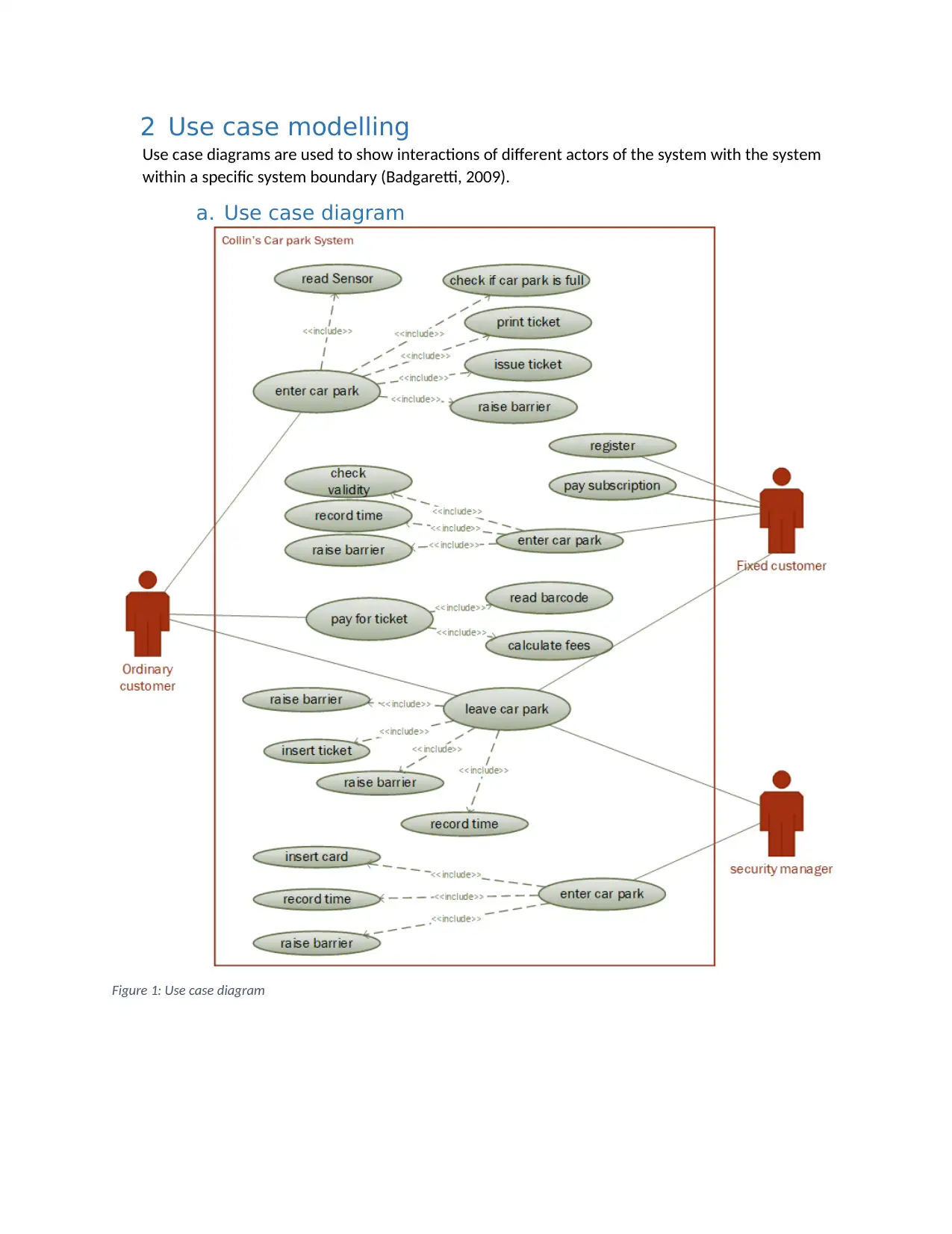
2 Use case modelling
Use case diagrams are used to show interactions of different actors of the system with the system
within a specific system boundary (Badgaretti, 2009).
a. Use case diagram
Figure 1: Use case diagram
Use case diagrams are used to show interactions of different actors of the system with the system
within a specific system boundary (Badgaretti, 2009).
a. Use case diagram
Figure 1: Use case diagram
⊘ This is a preview!⊘
Do you want full access?
Subscribe today to unlock all pages.
Trusted by 1+ million students worldwide
b. Use case descriptions
Based on the use case diagram in figure 1, Collin’s car park system has the following use cases.
Enter car park use case (ordinary customers) - For ordinary customers entering the car park the
system accomplishes this operation through this use case. The system reads the sensors to
prompt the user to prompt the button, then checks if the car park is full prints a tickets and
dispatches it to the user. The entry barriers is then raised.
Pay ticket (ordinary customer) - An ordinary customer pays for a ticket using the system through
this use case. To pay for a ticket, after inserting it in the pay station the system reads the
barcode and calculate the fees. The system then processes the payment and dispatches the
ticket back to the user.
Pay subscription (fixed customer) - a fixed customer pays for a subscription using the system by
using this method. The user pays for a subscription using this use case. To pays for a subscription
the user selects the subscription type for example weekly or monthly and then enters the
payment details. The system processes the payment and prints the ticket for the user.
Enter car park (fixed customer) - A fixed customer enters the car park using the system through
this use case. The user enters the ticket and the ticket is verified and entry time recorded and
the barrier is raised as the ticket Is dispatched back to the user
Enter car park (Security person) - A security person enters the car park through this use case.
The user enters the receipt in the entry station and the system records the entry time of the
security person.
Leave car park (ordinary customer, fixed customer and security person) – To leave the car park,
the user uses this use case. Leaving the car park involves inserting the ticket in the exit station
and the system verifies the ticket for ordinary customers. For ordinary customers and security
persons the ticket is dispatched back to the user and the barrier is raised.
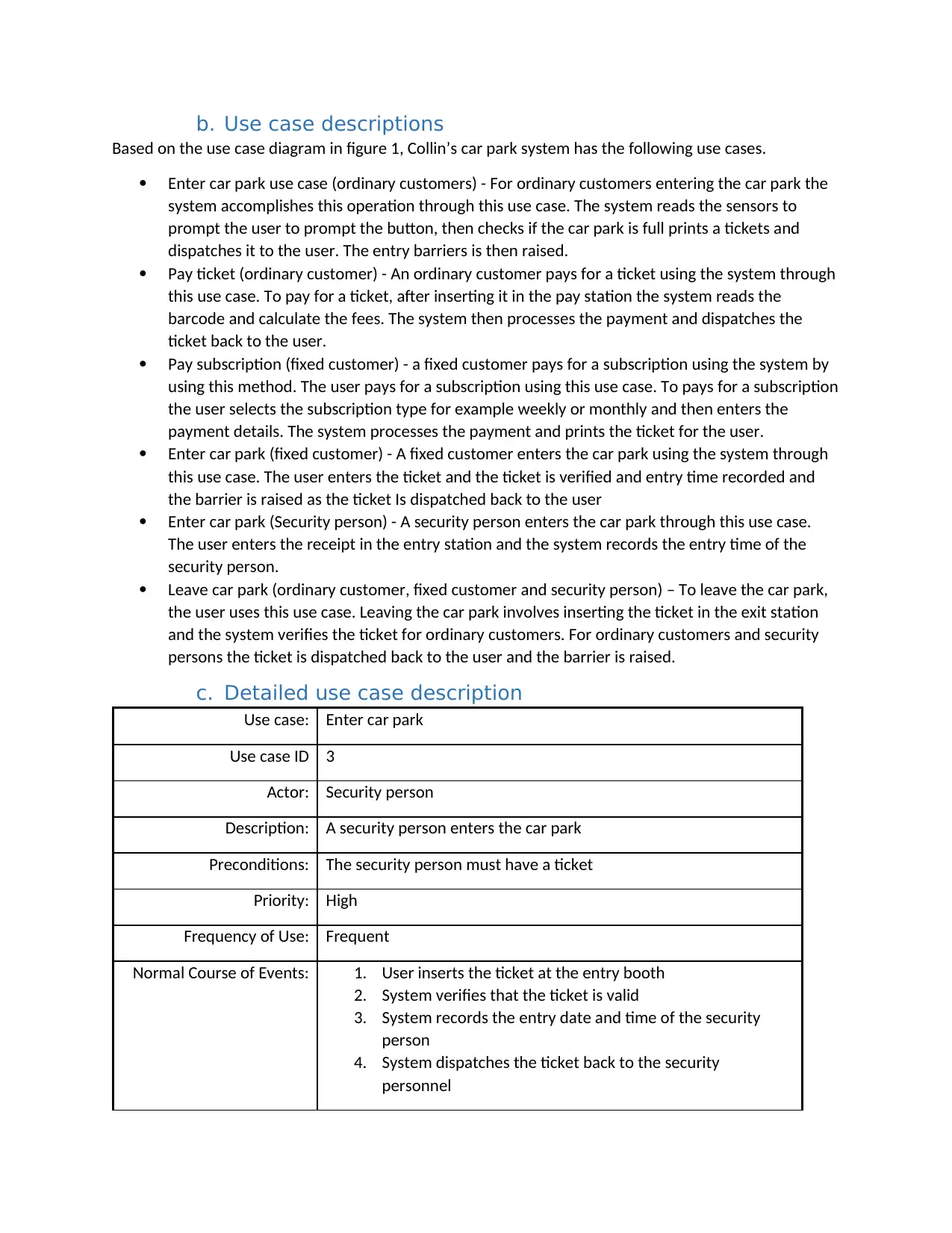
c. Detailed use case description
Use case: Enter car park
Use case ID 3
Actor: Security person
Description: A security person enters the car park
Preconditions: The security person must have a ticket
Priority: High
Frequency of Use: Frequent
Normal Course of Events: 1. User inserts the ticket at the entry booth
2. System verifies that the ticket is valid
3. System records the entry date and time of the security
person
4. System dispatches the ticket back to the security
personnel
Based on the use case diagram in figure 1, Collin’s car park system has the following use cases.
Enter car park use case (ordinary customers) - For ordinary customers entering the car park the
system accomplishes this operation through this use case. The system reads the sensors to
prompt the user to prompt the button, then checks if the car park is full prints a tickets and
dispatches it to the user. The entry barriers is then raised.
Pay ticket (ordinary customer) - An ordinary customer pays for a ticket using the system through
this use case. To pay for a ticket, after inserting it in the pay station the system reads the
barcode and calculate the fees. The system then processes the payment and dispatches the
ticket back to the user.
Pay subscription (fixed customer) - a fixed customer pays for a subscription using the system by
using this method. The user pays for a subscription using this use case. To pays for a subscription
the user selects the subscription type for example weekly or monthly and then enters the
payment details. The system processes the payment and prints the ticket for the user.
Enter car park (fixed customer) - A fixed customer enters the car park using the system through
this use case. The user enters the ticket and the ticket is verified and entry time recorded and
the barrier is raised as the ticket Is dispatched back to the user
Enter car park (Security person) - A security person enters the car park through this use case.
The user enters the receipt in the entry station and the system records the entry time of the
security person.
Leave car park (ordinary customer, fixed customer and security person) – To leave the car park,
the user uses this use case. Leaving the car park involves inserting the ticket in the exit station
and the system verifies the ticket for ordinary customers. For ordinary customers and security
persons the ticket is dispatched back to the user and the barrier is raised.
c. Detailed use case description
Use case: Enter car park
Use case ID 3
Actor: Security person
Description: A security person enters the car park
Preconditions: The security person must have a ticket
Priority: High
Frequency of Use: Frequent
Normal Course of Events: 1. User inserts the ticket at the entry booth
2. System verifies that the ticket is valid
3. System records the entry date and time of the security
person
4. System dispatches the ticket back to the security
personnel
Paraphrase This Document
Need a fresh take? Get an instant paraphrase of this document with our AI Paraphraser
5. System raises the barrier
Alternative Courses: 2. system verifies that the ticket is valid
2.1 System prompts the user to check the ticket
Exceptions: A security personnel can enter the car park without a car when
there is congestion at the entry station
Includes: Read barcode, record entry date and time
Assumptions: The security person is given a ticket by the company
3 Class diagram
The class diagram will be used to show the structural model of the proposed system (Bell, 2004).
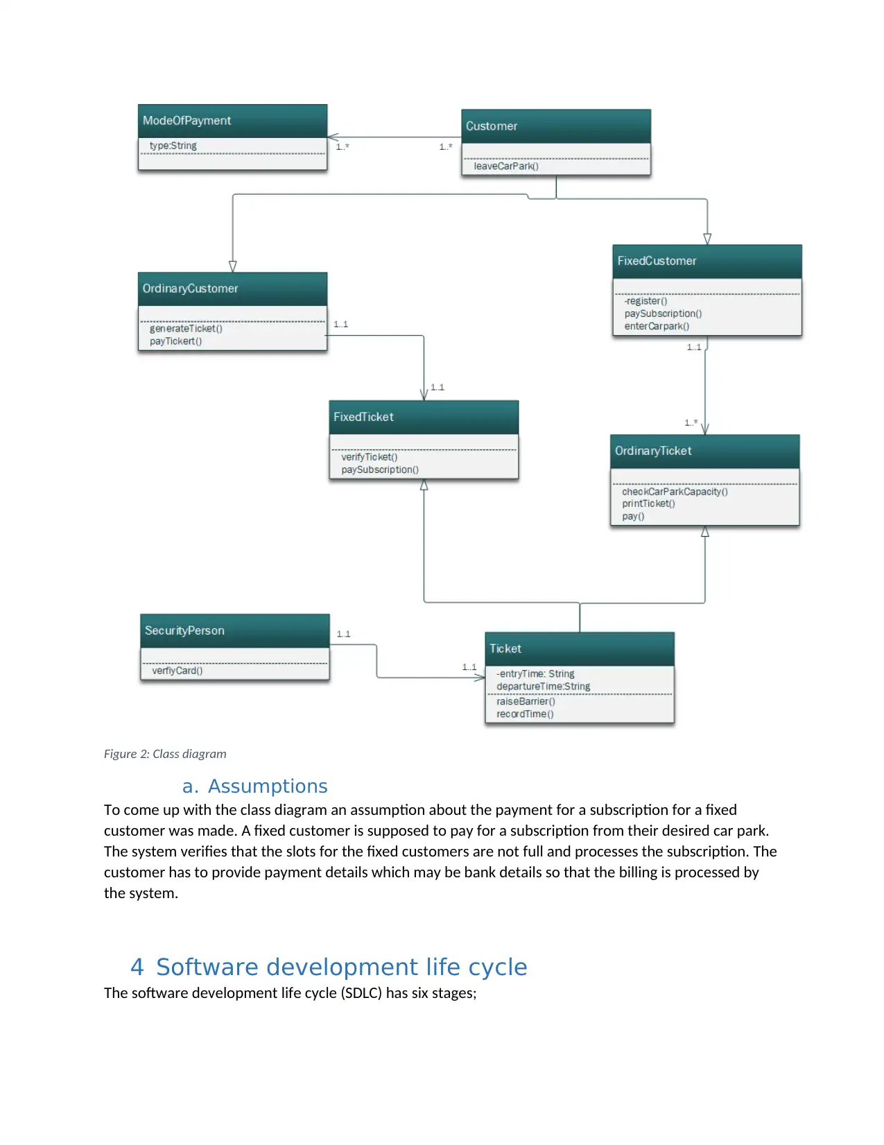
Figure 2: Class diagram
a. Assumptions
To come up with the class diagram an assumption about the payment for a subscription for a fixed
customer was made. A fixed customer is supposed to pay for a subscription from their desired car park.
The system verifies that the slots for the fixed customers are not full and processes the subscription. The
customer has to provide payment details which may be bank details so that the billing is processed by
the system.
4 Software development life cycle
The software development life cycle (SDLC) has six stages;
⊘ This is a preview!⊘
Do you want full access?
Subscribe today to unlock all pages.
Trusted by 1+ million students worldwide
Planning phase- At this phase all the project planning is done. Planning involves coming up with
the project schedule and the project plan to determine the project cost and resources required
to implement the project. This phase will also involve determining the methods to be used to
gather requirements and the implementation method.
Analysis phase- In the analysis phase an analysis of the project plan is done. All the requirements
are also analyzed to come up with software specifications document. This document will then be
used in the design phase.
Design phase- The design phase of the project involves coming up with a design from the
software specifications document achieved in the analysis phase.
Implementation phase- the implementation phase of the project is where the design is
implemented to achieve all the functional requirements. Testing is also done at this stage to
make sure all the non-functional requirements have been followed.
Deployment phase- After the implementation is finished the next step is the deployment of the
complete system for use at the car parks.
Maintenance phase- Maintenance phase involves maintaining the system in case of bugs and
updates to improve the system.
5 References
Ambler, S. (2018). Strategies for Capturing Non-Functional Requirements. Retrieved from
http://www.disciplinedagiledelivery.com/capturing-non-functional-requirements/
Badgareti. (2009). Software Engineering – Use Case Diagrams / Descriptions. Retrieved from
https://computersciencesource.wordpress.com/2009/11/22/year-2-software-engineering-
use-case-diagrams-descriptions/
Bell, D. (2004). The class diagram. Retrieved from
https://www.ibm.com/developerworks/rational/library/content/RationalEdge/sep04/bell/
index.html
Labunisky, E. (2017). What comes first: Functional or non-Functional Requirements?. Retrieved from
https://medium.com/agiletransformation/what-comes-first-functional-or-non-functional-
requirements-b3ee96424742
1 out of 10
Related Documents


Your All-in-One AI-Powered Toolkit for Academic Success.
+13062052269
info@desklib.com
Available 24*7 on WhatsApp / Email
![[object Object]](/_next/static/media/star-bottom.7253800d.svg)
Unlock your academic potential
Copyright © 2020–2026 A2Z Services. All Rights Reserved. Developed and managed by ZUCOL.