Carbon Fiber Composite Report: Disadvantages and Stacking Methodology
VerifiedAdded on 2022/09/08
|18
|3863
|10
Report
AI Summary
This report delves into the realm of carbon fiber composites, examining their application in the context of product realization and material science. It begins by highlighting the advantages of carbon fiber, such as its high strength-to-weight ratio, which has made it a key material in industries like wind power and aerospace. The report then pivots to address the disadvantages, including production waste and recycling challenges. A significant portion of the report is dedicated to the limitations of carbon fiber in aircraft manufacturing, particularly concerning the fuselage of remote-controlled airplanes, focusing on processing costs, impact resistance, and inspection challenges. The methodology section details the vacuum bagging process used for stacking, including the use of prepreg materials, peel ply, and breather fabric. It further describes the curing cycle, including temperature control and monitoring. The report presents the outcomes of mechanical testing, including graphs of standard travel against time and standard force against time. It also discusses the failure modes of the beam, such as shear failure, transverse failure, and brooming failure, and offers an analysis of these failure modes. Finally, the report references the British Standard BS EN ISO 14125:1998+A1:2011 for fiber-reinforced plastic composites and includes the specifications of XPREG XC110 component prepregs.

PRODUCT REALIZATION AND MATERIALS
By Name
Course
Instructor
Institution
Location
Date
By Name
Course
Instructor
Institution
Location
Date
Paraphrase This Document
Need a fresh take? Get an instant paraphrase of this document with our AI Paraphraser
Introduction
The clean economy is increasingly celebrating carbon fibre as a wonder material thanks to the
unique mixture of low weight and high strength that has seen it widely applied in the driving of
wind power revolution and rendering planes more efficient with regard to fuel consumption.
Turbine blades made from carbon fibres have been established to be longer as well as more rigid
in comparison with the conventional fibreglass models thereby rendering them significantly
resilient at the sea and the efficiency is even higher under conditions of fewer breezes (Zhu et al.,
2018).
However, behind the good and appreciable features of carbon lie what researchers call dirty
secret. Such is with regard to its wasteful nature in production as well as challenges with
recycling. Such has seen carbon fibre listed as being one of the leading materials that might
create waste challenges in the coming decades lest swift and strict measures are taken that would
see it readily for reuse and recycling. Among the possible options that might aid in combating
the challenge would be diversion of the carbon fibre from landfill which if attained might give a
platform for use of recycled carbon fibres in automobiles, and bikes alongside numerous other
applications. such would as well leading to saving of a lot of energy as the production of virgin
material tends to be the most energy intensive of all the process involved in the manufacture of
carbon fibre.
Disadvantages using of carbon fiber composite in manufacturing aircraft fuselage and
specifically in remote control airplane
The major disadvantages that limit the application of carbon fibers in aircraft and specifically
fuselage revolve around the processing as well as material costs, tolerance to damage,
dimensional tolerance, inspection and repair besides conservatism linked with the risks on
relatively new and other times variable materials. Carbon fiber is often stronger in terms of the
tensile as well as compressive strength and has been established to be of higher bending stiffness.
It has as well been found to be significantly lighter in comparison with fiber glass (Ma, Centea
and Nutt, 2017). Nevertheless, it is significantly poor with regard to resistance of impact as the
fibers tender to be quite brittle and thereby shattering when subjected to sharp impact.
The most important disadvantage of carbon fibre is the lack of visual proof of damage. Carbon
fibre respond have a different response from the other structural members to impact and there is
normally no specific sign of damage. For instance in case a car backs into a fuselage made of
aluminium, the fuselage may be dented and suppose the fuselage is not dented then there would
be no damage noted. In case the fuselage undergoes denting, the damage would be visible and
thus repairs can be initiated.
In a carbon fiber structure, a low energy impact for instance a tool drop or bump might not
necessarily leave behind a trail indicating a notable sign of the impact on the given surface (Park,
Lee and Song, 2018). Below the impact site, there could be mass delminations, spreading which
spreads in a cone-shaped region from the location of the impact. The damage on the structure
backside might be elaborate as well as significant even though it might be not visible from the
view. Such leaves a burden of responsibility that any time one would have a reason to believe
there could be an impact, minor as it may be, it would be proper that inspection is done to
establish if there could be an underlying damage on the structure.
In case an impact leads to delaminations, resulting in a crush of the surface or even a puncture, a
repair exercise becomes mandatory for the structure to be restored. As the damaged region waits
for repair it ought to be covered as well as protected from the extreme effects of rain. Most of the
⊘ This is a preview!⊘
Do you want full access?
Subscribe today to unlock all pages.
Trusted by 1+ million students worldwide
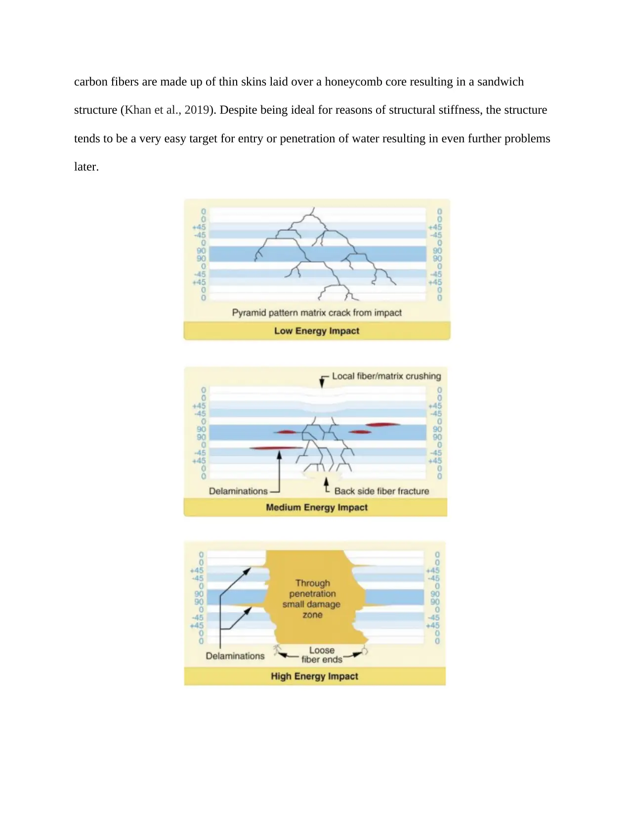
carbon fibers are made up of thin skins laid over a honeycomb core resulting in a sandwich
structure (Khan et al., 2019). Despite being ideal for reasons of structural stiffness, the structure
tends to be a very easy target for entry or penetration of water resulting in even further problems
later.
structure (Khan et al., 2019). Despite being ideal for reasons of structural stiffness, the structure
tends to be a very easy target for entry or penetration of water resulting in even further problems
later.
Paraphrase This Document
Need a fresh take? Get an instant paraphrase of this document with our AI Paraphraser
Another disadvantage of the use of carbon fiber is the possibility of damage by heat to the resin.
In as much as too hot is a factor of the given resign systems most of the epoxies start weaken
when the temperatures go beyond 150⁰F. white paint on carbon fiber is normally used in the
minimization of the challenge for instance the bottom of a wing which has a black paint facing a
black asphalt ramp on day that is sunny and hot may become as hot as 220⁰. When the same
structure is painted in white color would seldom get to a temperature higher than 140⁰F
(Patterson, 2018). For such reason carbon fiber airplanes normally have specified
recommendations on permitted paint colors. In case the plane is repainted, such
recommendations have to be adhered to. Damage by heat may as well take place as a result of
fire. Be it a small fast extinguished small brake fire has the potential of destroying the bottom
wing skins, composite landing gear legs or even the wheel pants.
Still, chemical paint strippers as well have quite harmful effects on the carbon fibers and hence
their use on the fiber has to be avoided. In case there is need to remove paint from carbon fiber,
only mechanical methods are advisable for instance gentle grit blasting or even sanding (Hassan,
Othman and Kamaruddin, 2017). Numerous expensive composite segments have been
completely damage by using paint stripper and such damages are often beyond repair.
Methodology behind the stacking
The method used for stacking in such experiment was vacuum bagging. Such is one of the most
commonly used methods in the composites industries and involves the creation of a uniform
pressure on the surface of an object placed inside a bag holding the segments together even as
the adhesive undergoes curing. Subjecting a composite to pressure is done to achieve numerous
objectives. It aids in the removal of any air that might be trapped between the layers as well as
offering pressure which serves to prevent shifting of the orientation of the fiber during the
process of curing. Such process also serves to lower the humidity besides enhancing the ration of
fiber to resin in the composite part.
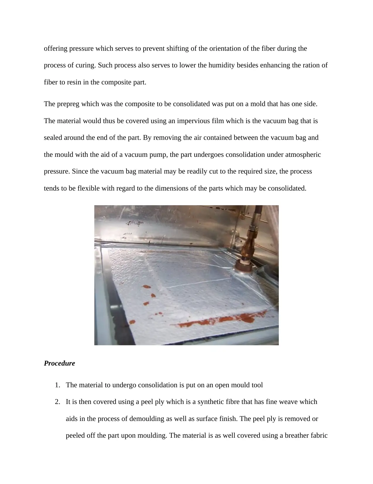
The prepreg which was the composite to be consolidated was put on a mold that has one side.
The material would thus be covered using an impervious film which is the vacuum bag that is
sealed around the end of the part. By removing the air contained between the vacuum bag and
the mould with the aid of a vacuum pump, the part undergoes consolidation under atmospheric
pressure. Since the vacuum bag material may be readily cut to the required size, the process
tends to be flexible with regard to the dimensions of the parts which may be consolidated.
Procedure
1. The material to undergo consolidation is put on an open mould tool
2. It is then covered using a peel ply which is a synthetic fibre that has fine weave which
aids in the process of demoulding as well as surface finish. The peel ply is removed or
peeled off the part upon moulding. The material is as well covered using a breather fabric
process of curing. Such process also serves to lower the humidity besides enhancing the ration of
fiber to resin in the composite part.
The prepreg which was the composite to be consolidated was put on a mold that has one side.
The material would thus be covered using an impervious film which is the vacuum bag that is
sealed around the end of the part. By removing the air contained between the vacuum bag and
the mould with the aid of a vacuum pump, the part undergoes consolidation under atmospheric
pressure. Since the vacuum bag material may be readily cut to the required size, the process
tends to be flexible with regard to the dimensions of the parts which may be consolidated.
Procedure
1. The material to undergo consolidation is put on an open mould tool
2. It is then covered using a peel ply which is a synthetic fibre that has fine weave which
aids in the process of demoulding as well as surface finish. The peel ply is removed or
peeled off the part upon moulding. The material is as well covered using a breather fabric
⊘ This is a preview!⊘
Do you want full access?
Subscribe today to unlock all pages.
Trusted by 1+ million students worldwide
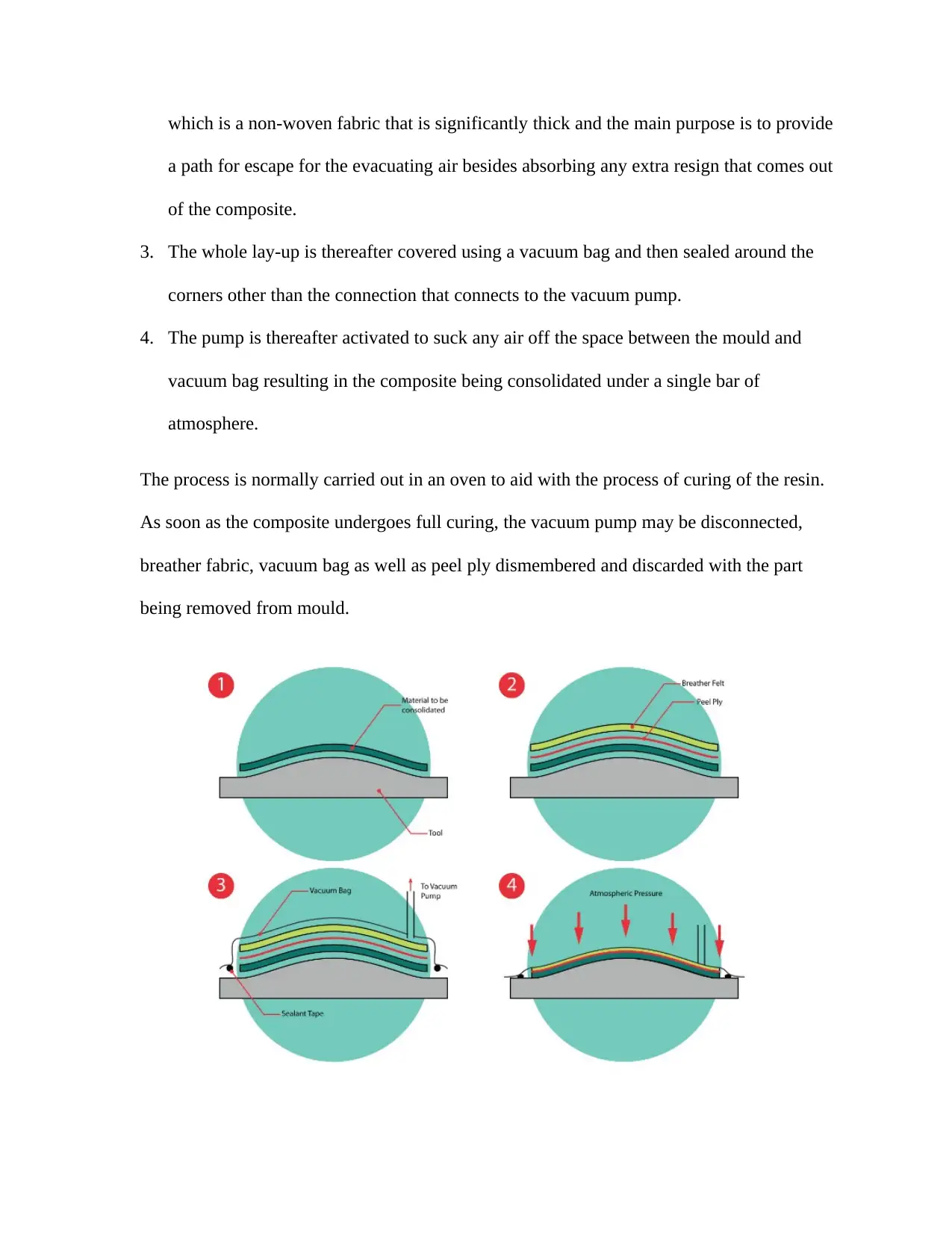
which is a non-woven fabric that is significantly thick and the main purpose is to provide
a path for escape for the evacuating air besides absorbing any extra resign that comes out
of the composite.
3. The whole lay-up is thereafter covered using a vacuum bag and then sealed around the
corners other than the connection that connects to the vacuum pump.
4. The pump is thereafter activated to suck any air off the space between the mould and
vacuum bag resulting in the composite being consolidated under a single bar of
atmosphere.
The process is normally carried out in an oven to aid with the process of curing of the resin.
As soon as the composite undergoes full curing, the vacuum pump may be disconnected,
breather fabric, vacuum bag as well as peel ply dismembered and discarded with the part
being removed from mould.
Paraphrase This Document
Need a fresh take? Get an instant paraphrase of this document with our AI Paraphraser
Curing Cycle
Care was taken in the vacuum bagging process to ensure the optimum surface finish as well as
mechanical performance of the manufactured prepreg is attained. Such was attained by the
adoption of the appropriate cure cycle. The cure cycle used in such process is for oven air
temperature such allowing for typical lag as a result of standard composite tooling. Monitoring
of the tool surface was conducted as heavy mould tools were used. Such was to ensure the lag
does not exceed the permissible limits. The temperatures were maintained between -3⁰C and 3⁰C
where most applicable. Ovens ought to be checked at intervals to ascertain they are attaining the
recommended levels of stability as well as accuracy. The standard cure cycle was adopted for the
experiment as it is recommended for application on laminates that are of moderate complexity
going to the tune of 4 plies providing the least time of processing of 7 hours 15 mins to attain an
excellent finish of the surface as well as low void content in a number of applications.
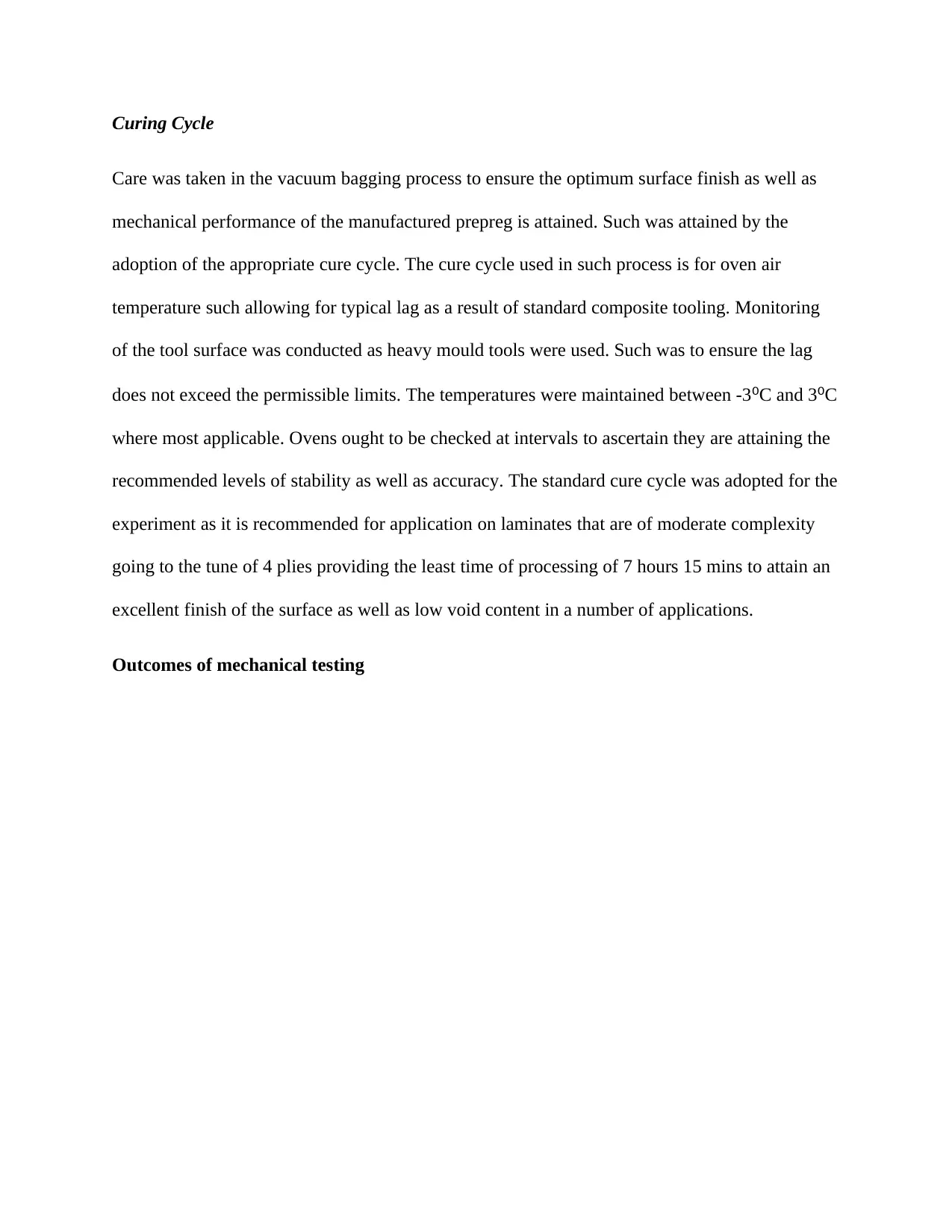
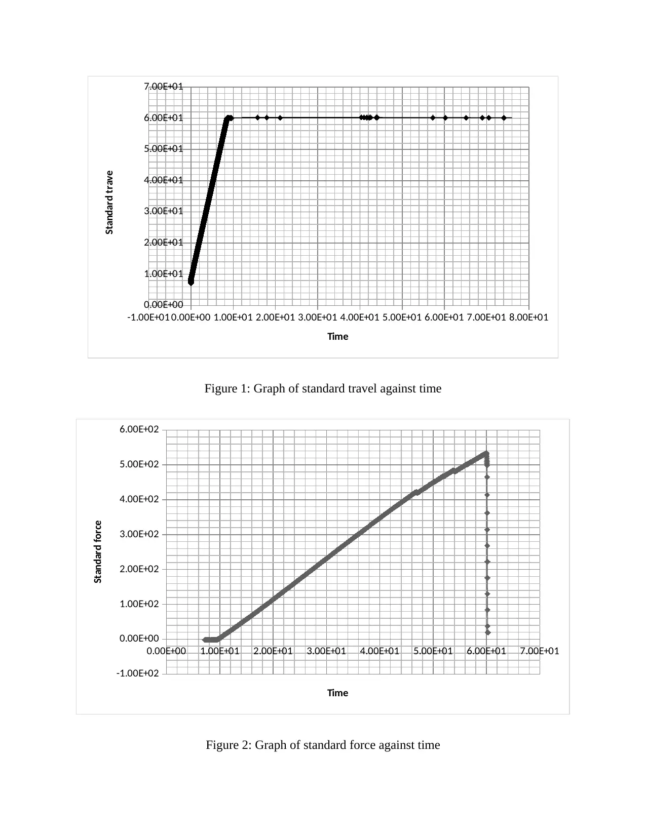
Outcomes of mechanical testing
Care was taken in the vacuum bagging process to ensure the optimum surface finish as well as
mechanical performance of the manufactured prepreg is attained. Such was attained by the
adoption of the appropriate cure cycle. The cure cycle used in such process is for oven air
temperature such allowing for typical lag as a result of standard composite tooling. Monitoring
of the tool surface was conducted as heavy mould tools were used. Such was to ensure the lag
does not exceed the permissible limits. The temperatures were maintained between -3⁰C and 3⁰C
where most applicable. Ovens ought to be checked at intervals to ascertain they are attaining the
recommended levels of stability as well as accuracy. The standard cure cycle was adopted for the
experiment as it is recommended for application on laminates that are of moderate complexity
going to the tune of 4 plies providing the least time of processing of 7 hours 15 mins to attain an
excellent finish of the surface as well as low void content in a number of applications.
Outcomes of mechanical testing
-1.00E+01 0.00E+00 1.00E+01 2.00E+01 3.00E+01 4.00E+01 5.00E+01 6.00E+01 7.00E+01 8.00E+01
0.00E+00
1.00E+01
2.00E+01
3.00E+01
4.00E+01
5.00E+01
6.00E+01
7.00E+01
Time
Standard trave
Figure 1: Graph of standard travel against time
0.00E+00 1.00E+01 2.00E+01 3.00E+01 4.00E+01 5.00E+01 6.00E+01 7.00E+01
-1.00E+02
0.00E+00
1.00E+02
2.00E+02
3.00E+02
4.00E+02
5.00E+02
6.00E+02
Time
Standard force
Figure 2: Graph of standard force against time
0.00E+00
1.00E+01
2.00E+01
3.00E+01
4.00E+01
5.00E+01
6.00E+01
7.00E+01
Time
Standard trave
Figure 1: Graph of standard travel against time
0.00E+00 1.00E+01 2.00E+01 3.00E+01 4.00E+01 5.00E+01 6.00E+01 7.00E+01
-1.00E+02
0.00E+00
1.00E+02
2.00E+02
3.00E+02
4.00E+02
5.00E+02
6.00E+02
Time
Standard force
Figure 2: Graph of standard force against time
⊘ This is a preview!⊘
Do you want full access?
Subscribe today to unlock all pages.
Trusted by 1+ million students worldwide
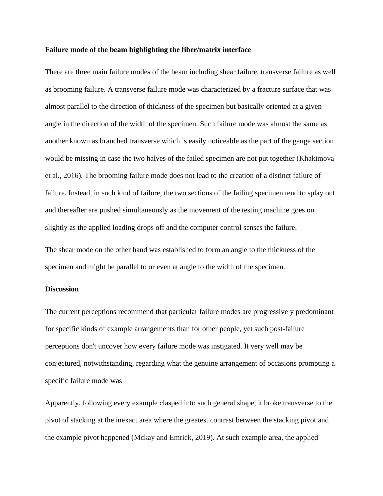
Failure mode of the beam highlighting the fiber/matrix interface
There are three main failure modes of the beam including shear failure, transverse failure as well
as brooming failure. A transverse failure mode was characterized by a fracture surface that was
almost parallel to the direction of thickness of the specimen but basically oriented at a given
angle in the direction of the width of the specimen. Such failure mode was almost the same as
another known as branched transverse which is easily noticeable as the part of the gauge section
would be missing in case the two halves of the failed specimen are not put together (Khakimova
et al., 2016). The brooming failure mode does not lead to the creation of a distinct failure of
failure. Instead, in such kind of failure, the two sections of the failing specimen tend to splay out
and thereafter are pushed simultaneously as the movement of the testing machine goes on
slightly as the applied loading drops off and the computer control senses the failure.
The shear mode on the other hand was established to form an angle to the thickness of the
specimen and might be parallel to or even at angle to the width of the specimen.
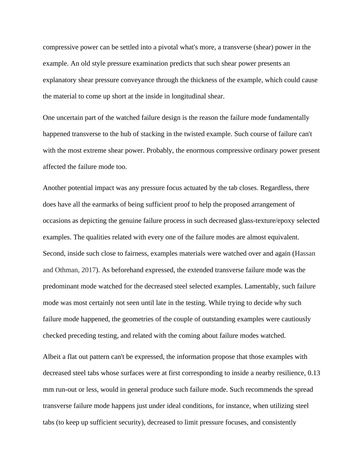
Discussion
The current perceptions recommend that particular failure modes are progressively predominant
for specific kinds of example arrangements than for other people, yet such post-failure
perceptions don't uncover how every failure mode was instigated. It very well may be
conjectured, notwithstanding, regarding what the genuine arrangement of occasions prompting a
specific failure mode was
Apparently, following every example clasped into such general shape, it broke transverse to the
pivot of stacking at the inexact area where the greatest contrast between the stacking pivot and
the example pivot happened (Mckay and Emrick, 2019). At such example area, the applied
There are three main failure modes of the beam including shear failure, transverse failure as well
as brooming failure. A transverse failure mode was characterized by a fracture surface that was
almost parallel to the direction of thickness of the specimen but basically oriented at a given
angle in the direction of the width of the specimen. Such failure mode was almost the same as
another known as branched transverse which is easily noticeable as the part of the gauge section
would be missing in case the two halves of the failed specimen are not put together (Khakimova
et al., 2016). The brooming failure mode does not lead to the creation of a distinct failure of
failure. Instead, in such kind of failure, the two sections of the failing specimen tend to splay out
and thereafter are pushed simultaneously as the movement of the testing machine goes on
slightly as the applied loading drops off and the computer control senses the failure.
The shear mode on the other hand was established to form an angle to the thickness of the
specimen and might be parallel to or even at angle to the width of the specimen.
Discussion
The current perceptions recommend that particular failure modes are progressively predominant
for specific kinds of example arrangements than for other people, yet such post-failure
perceptions don't uncover how every failure mode was instigated. It very well may be
conjectured, notwithstanding, regarding what the genuine arrangement of occasions prompting a
specific failure mode was
Apparently, following every example clasped into such general shape, it broke transverse to the
pivot of stacking at the inexact area where the greatest contrast between the stacking pivot and
the example pivot happened (Mckay and Emrick, 2019). At such example area, the applied
Paraphrase This Document
Need a fresh take? Get an instant paraphrase of this document with our AI Paraphraser
compressive power can be settled into a pivotal what's more, a transverse (shear) power in the
example. An old style pressure examination predicts that such shear power presents an
explanatory shear pressure conveyance through the thickness of the example, which could cause
the material to come up short at the inside in longitudinal shear.
One uncertain part of the watched failure design is the reason the failure mode fundamentally
happened transverse to the hub of stacking in the twisted example. Such course of failure can't
with the most extreme shear power. Probably, the enormous compressive ordinary power present
affected the failure mode too.
Another potential impact was any pressure focus actuated by the tab closes. Regardless, there
does have all the earmarks of being sufficient proof to help the proposed arrangement of
occasions as depicting the genuine failure process in such decreased glass-texture/epoxy selected
examples. The qualities related with every one of the failure modes are almost equivalent.
Second, inside such close to fairness, examples materials were watched over and again (Hassan
and Othman, 2017). As beforehand expressed, the extended transverse failure mode was the
predominant mode watched for the decreased steel selected examples. Lamentably, such failure
mode was most certainly not seen until late in the testing. While trying to decide why such
failure mode happened, the geometries of the couple of outstanding examples were cautiously
checked preceding testing, and related with the coming about failure modes watched.
Albeit a flat out pattern can't be expressed, the information propose that those examples with
decreased steel tabs whose surfaces were at first corresponding to inside a nearby resilience, 0.13
mm run-out or less, would in general produce such failure mode. Such recommends the spread
transverse failure mode happens just under ideal conditions, for instance, when utilizing steel
tabs (to keep up sufficient security), decreased to limit pressure focuses, and consistently
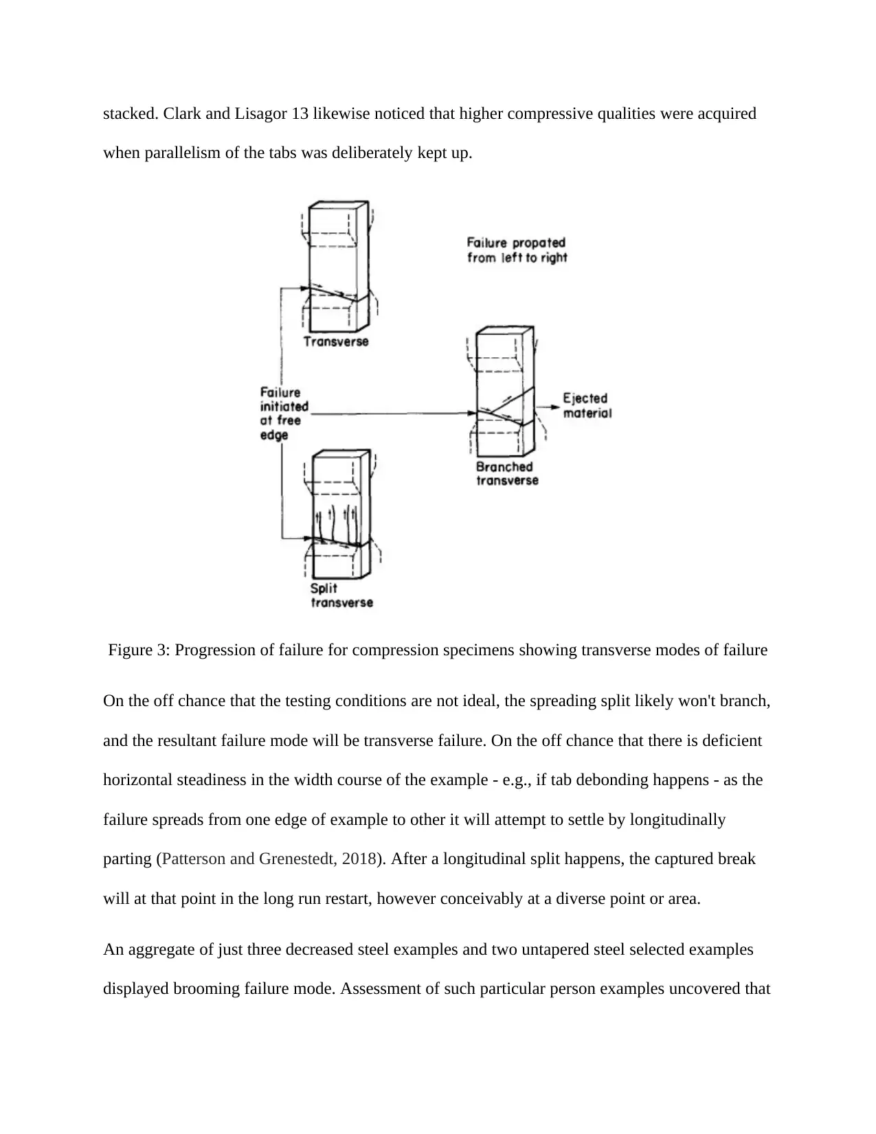
stacked. Clark and Lisagor 13 likewise noticed that higher compressive qualities were acquired
when parallelism of the tabs was deliberately kept up.
Figure 3: Progression of failure for compression specimens showing transverse modes of failure
On the off chance that the testing conditions are not ideal, the spreading split likely won't branch,
and the resultant failure mode will be transverse failure. On the off chance that there is deficient
horizontal steadiness in the width course of the example - e.g., if tab debonding happens - as the
failure spreads from one edge of example to other it will attempt to settle by longitudinally
parting (Patterson and Grenestedt, 2018). After a longitudinal split happens, the captured break
will at that point in the long run restart, however conceivably at a diverse point or area.
An aggregate of just three decreased steel examples and two untapered steel selected examples
displayed brooming failure mode. Assessment of such particular person examples uncovered that
⊘ This is a preview!⊘
Do you want full access?
Subscribe today to unlock all pages.
Trusted by 1+ million students worldwide
1 out of 18
Your All-in-One AI-Powered Toolkit for Academic Success.
+13062052269
info@desklib.com
Available 24*7 on WhatsApp / Email
![[object Object]](/_next/static/media/star-bottom.7253800d.svg)
Unlock your academic potential
Copyright © 2020–2026 A2Z Services. All Rights Reserved. Developed and managed by ZUCOL.