Research Methodology: CFRP Experiment and Finite Element Analysis
VerifiedAdded on 2022/07/28
|9
|1450
|20
Literature Review
AI Summary
This literature review focuses on the experimental and finite element analysis of Carbon Fiber Reinforced Polymer (CFRP). It explores the application of CFRP in structural applications due to its lightweight, high strength, and stability. The review discusses the challenges in CFRP manufacturing, particularly milling, and the importance of experimental studies to overcome machining difficulties. It details an experimental setup involving a milling machine and dynamometer to measure thrust force data. The review then moves to the finite element modeling of CFRP laminates, using ABAQUS software and Autodesk composite material manager, including the application of Hashin failure criteria. The document outlines the material properties, constitutive damage criteria, and the research gap identified, which is the finite element simulation and delayed analysis of contact gaps in CFRP materials. The review concludes by providing relevant references supporting the research.
1
RESEARCH METHODOLOGY
By Name
Course
Instructor
Institution
Location
Date
RESEARCH METHODOLOGY
By Name
Course
Instructor
Institution
Location
Date
Paraphrase This Document
Need a fresh take? Get an instant paraphrase of this document with our AI Paraphraser
2
EXPERIMENT AND FINITE ELEMENT ANALYSIS OF CARBON FIBRE
REINFORCED POLYMER
Literature Review
Carbon fiber polymers are used in applications which are in structural form because of their
features these features include their possession of light weight, their high strength, possession of
specific higher stiffness , stability on conventional alloys and metals and also low thermal
expansion [1].
One of the most commonly applied process of removing materials in the CFRPs manufacture is
milling. But unlike metal milling that is featured by high rates of material removal, in FRPs
milling operation system it is usually done only at a lower scale. Normally, manufacturing of
composites is done with specific and modern methods of manufacturing. Though, they require
machines in limited numbers that are traditional in nature [1]. These machines include milling
and drilling process machines in order to achieve the required shape. Milling and drilling
complexities is in orientation terms, chip size and forces of cutting that vary continuously with
the rotation of the tool. However, the CFRP features may have difficulties during composite
machining which can lead to unwanted damages in the surface that is machined. The machining
precision and damage of the laminate depend greatly on machining measurements especially the
feed rate and cutting velocity [2].
Even though it is expensive and time consuming studying the machining processes, it is
important to carry out an experimental study analysis in order for us to overcome difficulties
involved in machining.
3
Experimental study
The experiments of milling were done on a NAMMIL XL602AV, a vertically milling machine
with a spindle power 2 HP and a 1700 rpm maximum speed. A TiAIN coated solid carbide mill
cutter that was a 10 mm diameter which is the most favorite one that was attached in its universal
three-jaw chuck. Slot milling operation was conducted for various cutting feeds and speeds [3].
The speed recorded were 10.99m/min, 18.84m/min, 28.26m/mm and 53.38m/mm, for the feeds
they were 50mm/min, 150mm/min and 350mm/min.
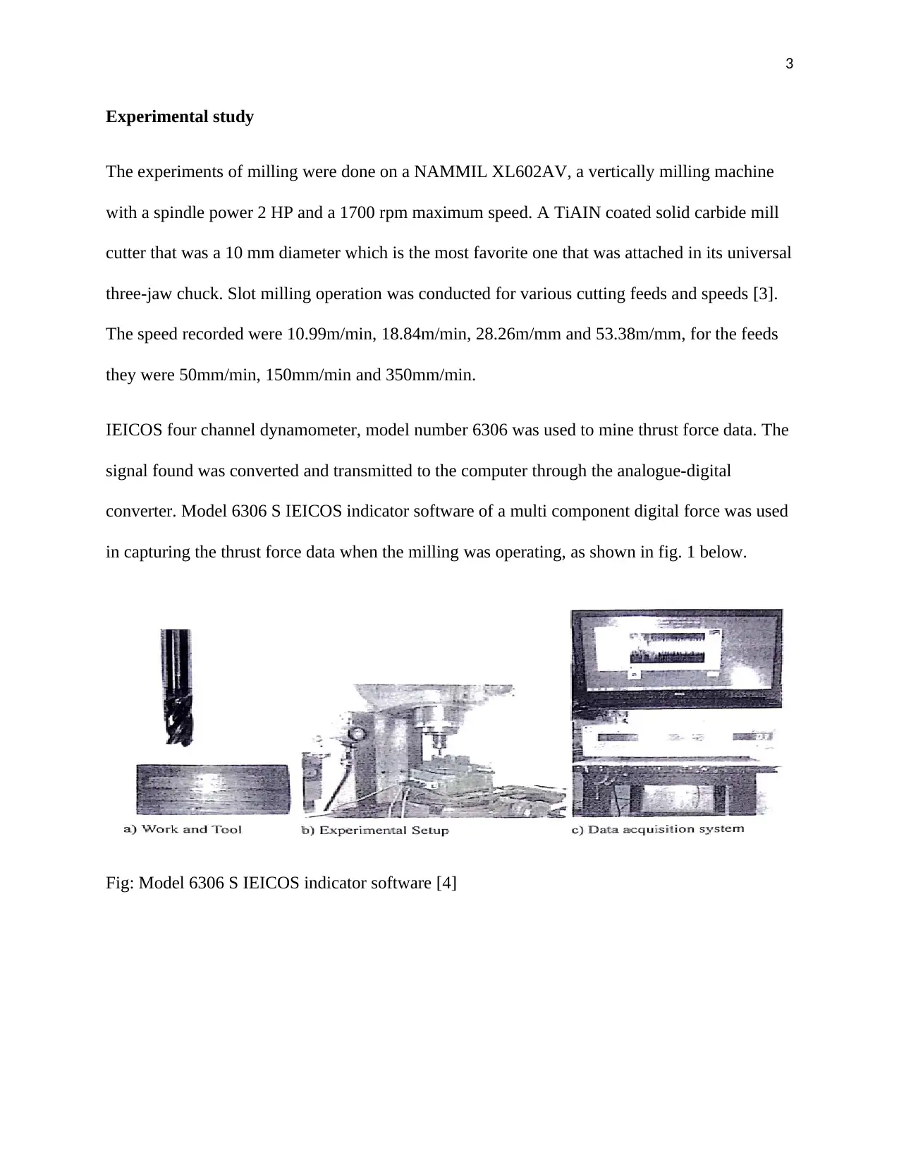
IEICOS four channel dynamometer, model number 6306 was used to mine thrust force data. The
signal found was converted and transmitted to the computer through the analogue-digital
converter. Model 6306 S IEICOS indicator software of a multi component digital force was used
in capturing the thrust force data when the milling was operating, as shown in fig. 1 below.
Fig: Model 6306 S IEICOS indicator software [4]
⊘ This is a preview!⊘
Do you want full access?
Subscribe today to unlock all pages.

Trusted by 1+ million students worldwide
4
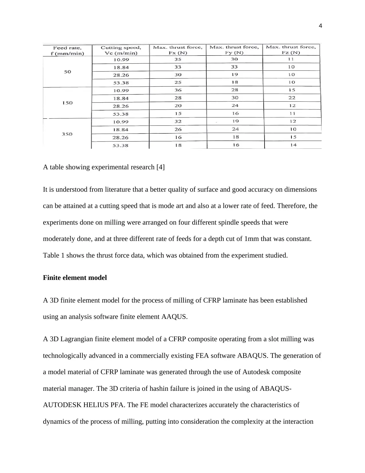
A table showing experimental research [4]
It is understood from literature that a better quality of surface and good accuracy on dimensions
can be attained at a cutting speed that is mode art and also at a lower rate of feed. Therefore, the
experiments done on milling were arranged on four different spindle speeds that were
moderately done, and at three different rate of feeds for a depth cut of 1mm that was constant.
Table 1 shows the thrust force data, which was obtained from the experiment studied.
Finite element model
A 3D finite element model for the process of milling of CFRP laminate has been established
using an analysis software finite element AAQUS.
A 3D Lagrangian finite element model of a CFRP composite operating from a slot milling was
technologically advanced in a commercially existing FEA software ABAQUS. The generation of
a model material of CFRP laminate was generated through the use of Autodesk composite
material manager. The 3D criteria of hashin failure is joined in the using of ABAQUS-
AUTODESK HELIUS PFA. The FE model characterizes accurately the characteristics of
dynamics of the process of milling, putting into consideration the complexity at the interaction
Paraphrase This Document
Need a fresh take? Get an instant paraphrase of this document with our AI Paraphraser
5
and geometry of end mill cutter properties between the work peace (CFRP laminate) and the tool
[5].
3D geometric model
CFRP unidirectional laminate was modeled in 3D by using module of part 6.14-2 with
dimensions of 25mm times 25mm times 10mm overall , thickness of only 0.7mm as shown in
figure 3. A solid carbide end mill cutter that is four fluted (SANDVIK H10F Grae with 115
degrees angle of the point and 30 degrees angle of helix) [6] of 10mm diameter was modeled in
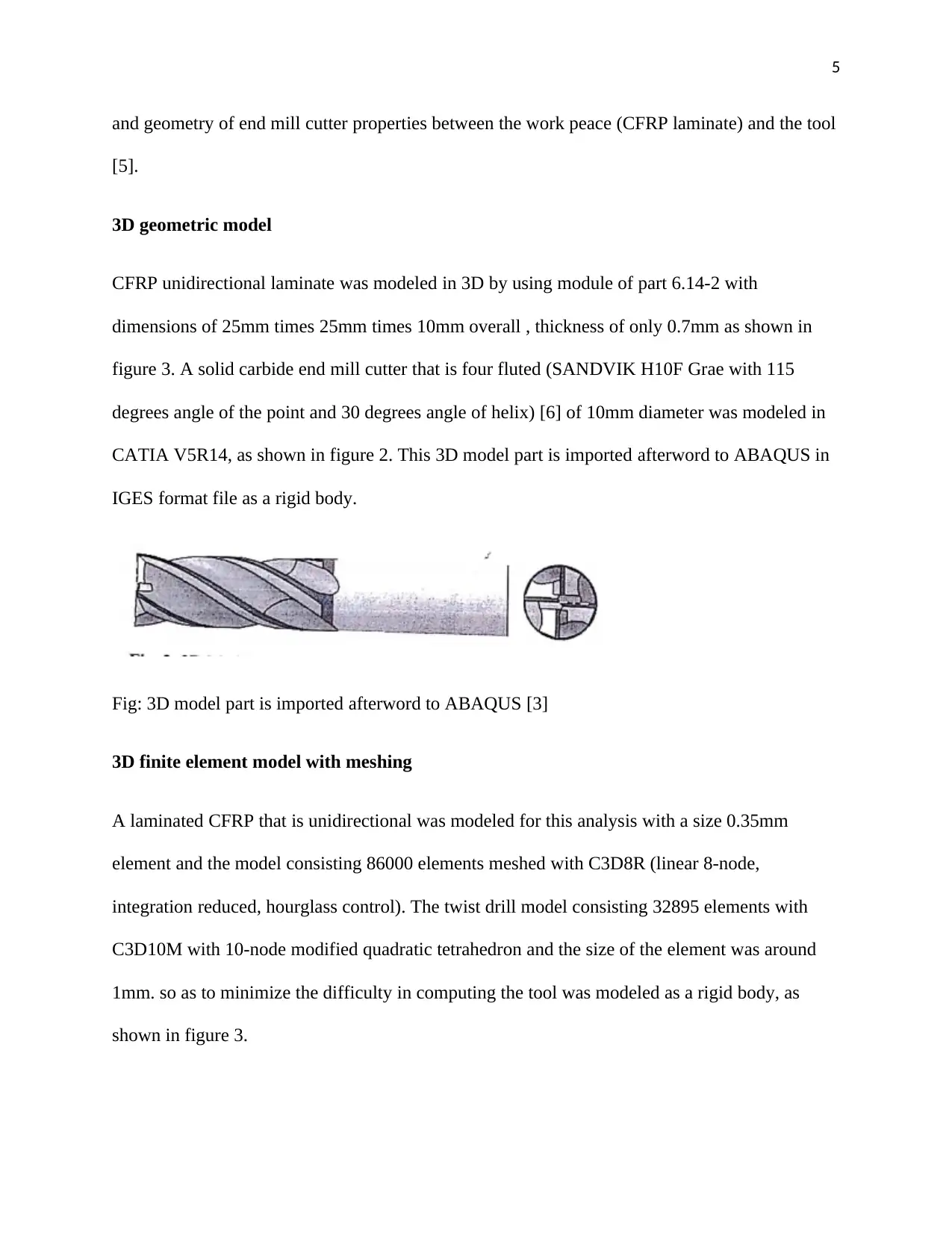
CATIA V5R14, as shown in figure 2. This 3D model part is imported afterword to ABAQUS in
IGES format file as a rigid body.
Fig: 3D model part is imported afterword to ABAQUS [3]
3D finite element model with meshing
A laminated CFRP that is unidirectional was modeled for this analysis with a size 0.35mm
element and the model consisting 86000 elements meshed with C3D8R (linear 8-node,
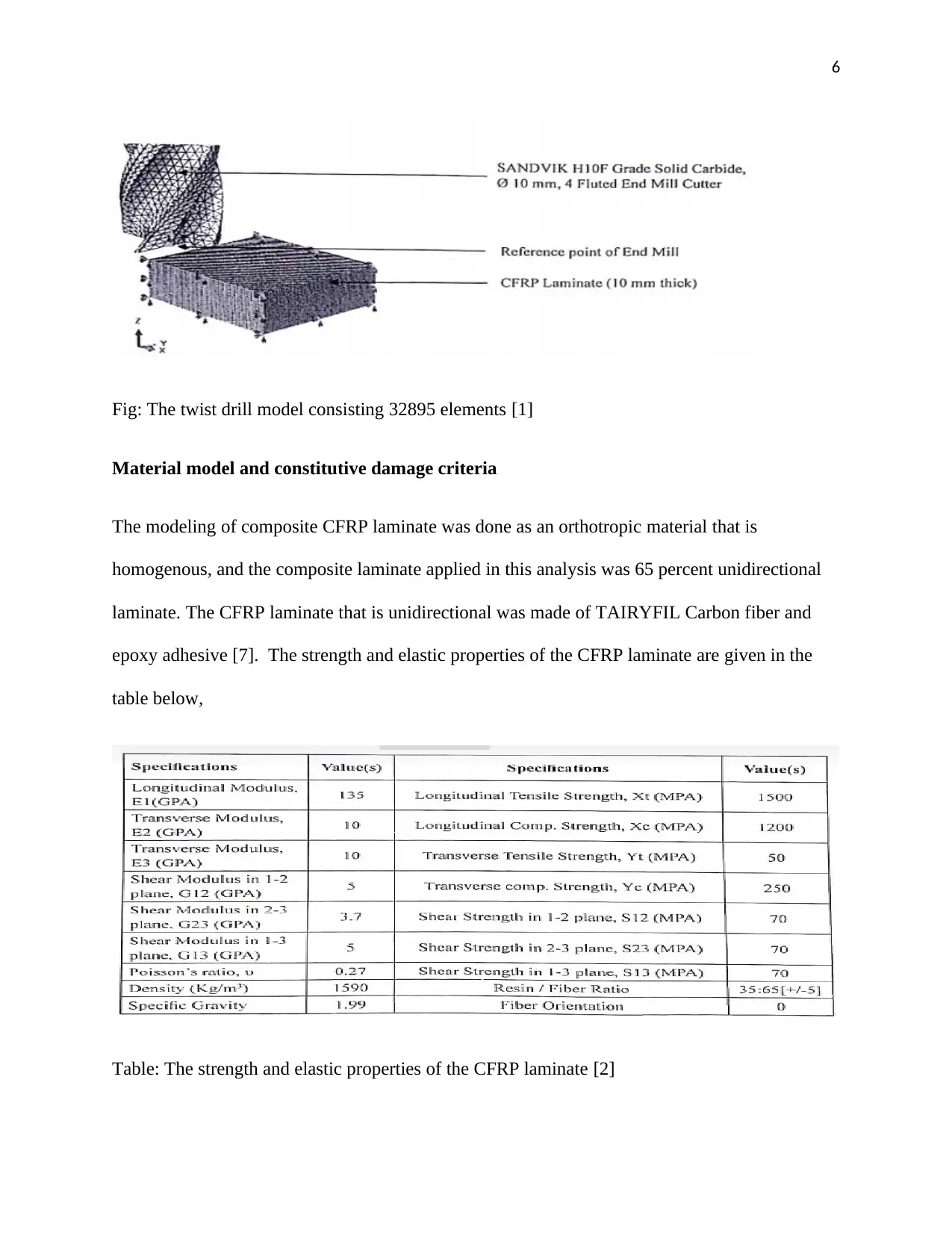
integration reduced, hourglass control). The twist drill model consisting 32895 elements with
C3D10M with 10-node modified quadratic tetrahedron and the size of the element was around
1mm. so as to minimize the difficulty in computing the tool was modeled as a rigid body, as
shown in figure 3.
6
Fig: The twist drill model consisting 32895 elements [1]
Material model and constitutive damage criteria
The modeling of composite CFRP laminate was done as an orthotropic material that is
homogenous, and the composite laminate applied in this analysis was 65 percent unidirectional
laminate. The CFRP laminate that is unidirectional was made of TAIRYFIL Carbon fiber and
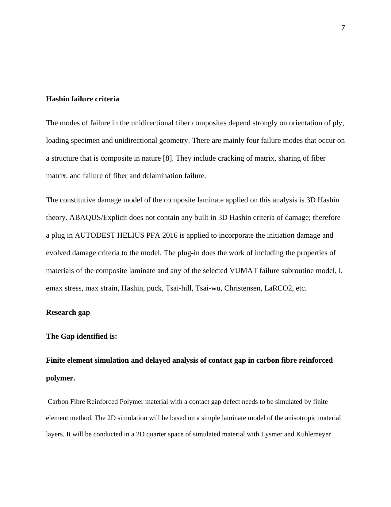
epoxy adhesive [7]. The strength and elastic properties of the CFRP laminate are given in the
table below,
Table: The strength and elastic properties of the CFRP laminate [2]
⊘ This is a preview!⊘
Do you want full access?
Subscribe today to unlock all pages.

Trusted by 1+ million students worldwide
7
Hashin failure criteria
The modes of failure in the unidirectional fiber composites depend strongly on orientation of ply,
loading specimen and unidirectional geometry. There are mainly four failure modes that occur on
a structure that is composite in nature [8]. They include cracking of matrix, sharing of fiber
matrix, and failure of fiber and delamination failure.
The constitutive damage model of the composite laminate applied on this analysis is 3D Hashin
theory. ABAQUS/Explicit does not contain any built in 3D Hashin criteria of damage; therefore
a plug in AUTODEST HELIUS PFA 2016 is applied to incorporate the initiation damage and
evolved damage criteria to the model. The plug-in does the work of including the properties of
materials of the composite laminate and any of the selected VUMAT failure subroutine model, i.
emax stress, max strain, Hashin, puck, Tsai-hill, Tsai-wu, Christensen, LaRCO2, etc.
Research gap
The Gap identified is:
Finite element simulation and delayed analysis of contact gap in carbon fibre reinforced
polymer.
Carbon Fibre Reinforced Polymer material with a contact gap defect needs to be simulated by finite
element method. The 2D simulation will be based on a simple laminate model of the anisotropic material
layers. It will be conducted in a 2D quarter space of simulated material with Lysmer and Kuhlemeyer
Paraphrase This Document
Need a fresh take? Get an instant paraphrase of this document with our AI Paraphraser
8
absorbing boundary conditions. The contact gap will be included in the epoxy layer near the receiving
transducer.
References
[1] Y. Liu, Carbon Fibre Reinforced Polymer (CFRP) Cables for Orthogonally Loaded Cable
Structures. Advantages and Feasibility, London: Logos Verlag Berlin GmbH, 2013.
[2] M. Jawaid, M. Thariq and N. Saba, Modelling of Damage Processes in Biocomposites,
Fibre-Reinforced Composites and Hybrid Composites, Texas: Elsevier Science, 2013.
[3] G. Gudimani, Oblique Machining of Uni Directional Carbon Fiber Reinforced Polymer
Composites, Sydney: Wichita State University, College of Engineering, Department of
Mechanical Engineering, 2016.
[4] X. J. Zhou, Advances in Structural Engineering, Chicago: Trans Tech Publications Ltd,
9
2017.
[5] M. Masuelli, Fiber Reinforced Polymers: The Technology Applied for Concrete Repair,
London: BoD – Books on Demand, 2019.
[6] J. Y. Zhao, Advances in Civil Engineering, Texas: Trans Tech Publications Ltd, 2010.
[7] H. Okada and S. Atluri, Computational and Experimental Simulations in Engineering,
Chicago: Springer Nature, 2014.
[8] C. Hiremath, Microstructural Damage Based Micromechanics Model to Predict Stiffness
Reduction in Damaged Unidirectional Composites, Berlin: Technomic Publishing Company,
2015.
⊘ This is a preview!⊘
Do you want full access?
Subscribe today to unlock all pages.

Trusted by 1+ million students worldwide
1 out of 9
Your All-in-One AI-Powered Toolkit for Academic Success.
+13062052269
info@desklib.com
Available 24*7 on WhatsApp / Email
![[object Object]](/_next/static/media/star-bottom.7253800d.svg)
Unlock your academic potential
Copyright © 2020–2026 A2Z Services. All Rights Reserved. Developed and managed by ZUCOL.

