Catamaran Design Project: Material Selection, Analysis, and Design
VerifiedAdded on 2022/11/14
|14
|2477
|268
Project
AI Summary
This project delves into the design of a catamaran, focusing on the selection of appropriate materials for key structural components. The executive summary highlights the importance of material properties like stiffness, strength, and durability, while also considering cost and build methodology. The design utilizes E-glass fiber for the beam, chosen for its high strength-to-weight ratio and corrosion resistance, reinforced with plastic resin. Stainless steel is selected for cable stays and support cables due to its high elastic modulus, essential for withstanding tensile forces. Detailed calculations are provided in the appendix to determine the dimensions and stress on the beam, cable stays, and support cables, ensuring the structural integrity of the catamaran under various loads, including wind loads. The conclusion emphasizes the rationale behind material selection and the importance of factors of safety in the overall design.
Catamaran Design
Name of student:
Institutional Affiliations:
Name of course:
Name of student:
Institutional Affiliations:
Name of course:
Paraphrase This Document
Need a fresh take? Get an instant paraphrase of this document with our AI Paraphraser
Executive summary
Materials vary in nature and the best selection depends on the stiffness, strength and durability of
each. However, it is important to take into consideration the cost implications of each material.
Moreover, each design is dependent on the methodology that is used for the eventual build. That
stated, in the design of the catamaran, there are two elements that have been used. The beam has
been designed using E-glass fiber while the cable stays and the support cables have been
designed using stainless steel. The flexural strength of the former has been imperative in the
beam design while the elastic modulus of the latter has played a big role in the cable stays and
support cable design.
The Beam Design
Like in many catamaran designs, the best material for use is glass fiber. In line with this, glass
fiber has been defined as a composite material that is composed of very minute filaments of glass
fiber that are woven into a yarn and eventually woven into a specified fabric (Karlson, 1993). In
line with this, the material has been chosen because of some of its properties which include high
strength and the durability.
. Given the strength and the young’s modulus of the glass fiber, it can be clearly seen that the
beam can withstand various loadings. On top of this, the material has been described to be very
durable and has the capability to withstand corrosion from water. However, in order to reinforce
the properties of the glass fiber, the design may also incorporate the use of plastic resin.
In line with a comparison of the other elements that have been listed, it is important to
understand that the strength and weight ratio is comparatively high in the glass fiber (Karlson,
1993). Nevertheless, one of the major strengths that is associated with the first design material,
glass fiber. This is among the most commendable materials when it comes to durability and
strength. In particular, the E-glass fiber that that has a composition of 54% silicon oxide, 12%
calcium oxide and 15% aluminum oxide may be one of the mist viable choices when it comes to
the beam design (Boyd, Blake, Shenoi, & Mawella, 2008).
It is important to understand that beams are an intricate part of the whole structure. They are
supposed to support a support base for the overall load emanating from the haul, the cable stays
and the mast. Therefore, the beam element needs to have significant strength to weight ratio.
However, the compressive strength, elastic strength and the endurance limit may be more
⊘ This is a preview!⊘
Do you want full access?
Subscribe today to unlock all pages.
Trusted by 1+ million students worldwide
important in this case. These properties ensure that the beam does not easily fracture under the
loads, ensuring durability of the catamaran
Material used in the design of the wire stays
The wire stays are designed in order to ensure that the catamaran stays in balance. On top of this,
these stays ensure that the load is equally distributed along the mat. This is not only important for
the durability of the catamaran; it also acts as a support for the extra load that may be imposed on
it (Callister & Rethwisch, 2017). In essence, the catamaran supports the dead load of the beam
and the mat and also the load that may be imposed later on to the catamaran.
In line with this, the mist recommended application of the cable stays is when they are used in
different strands. This is to say that the diameter of the cable stay may be composed of a number
of stainless steel strands (Karlson, 1993).
Looking at the cable stays, stainless steel has been the most preferred choice owing to its vast
properties. As a matter of fact, when it comes to the cable stays, the most significant property is
the elastic modulus (Luo, 2012). The compressive and tensile strengths of the materials are also
important but the design has to consider the cost implications associated with the other materials.
Nevertheless, the elastic modulus of the material is imperative because the cable stays are subject
to tensile forces which arise from the beam and the mat. These tensile forces, if not managed
properly, may lead to the collapse of the cable (Russell, 2005). Elastic limit, once reached, may
mean failure, according to Hooke’s law. In essence, it is important to select a material with one
of the highest elastic modulus and tensile strength (Ramesh, Palanikumar, & Reddy, 2013). In
line with this, the table indicates that the elastic modulus of steel is higher than that of all the
other elements, with the exception of silicon nitride. The manufacture of silicon nitride tends to
Paraphrase This Document
Need a fresh take? Get an instant paraphrase of this document with our AI Paraphraser
be expensive resulting to undesirable cost implications (Xu-ming, 2008). This is also regardless
of the tensile strength of the material. Therefore, the most distinguishable properties when it
comes to the selection of steel in design of the cable stays are the elastic modulus. Corrosion has
been of the essence when selecting the type of steel.
Material to be used in lifting the catamaran out of the water
Taking into consideration all the factors to be used in the analysis, stainless steel may be one of
the cheapest, yet efficient materials for use. This pertains to the elastic modulus and the yield
stress. However, in order to estimate the diameter for use, the most important factor is to look at
the total loading that the material may be subjected to (Russell, 2005). The mast, the cables, the
beam will all be fundamental in the design of the cable..
Nevertheless, it is important to consider other factors such as wind loads that may play a vital
role in the overall stability of the cable. This is to say that a proper factor of safety has to be
considered in the full design of the cable (Xu-ming, 2008). Nevertheless, calculating the size of
the cable will be dependent on the breaking strength associated with it (Callister & Rethwisch,
2017). That stated, this breaking strength is usually dependent on the cross sectional area and the
amount of load that is supported.
Conclusion
As it has been discussed in the aforementioned sections, there are two specific materials that may
be used in the design of the catamaran boat. The first material is the glass fiber, most preferably
reinforced with plastic, while the material used in the design of the cable stays is stainless steel.
Moreover, the cable that will be used in the extraction of the catamaran from the water needs to
be made from steel. The basics of selection of these types of material are the durability
properties, the yield strength, the elastic modulus which are far superior that of other materials.
⊘ This is a preview!⊘
Do you want full access?
Subscribe today to unlock all pages.
Trusted by 1+ million students worldwide
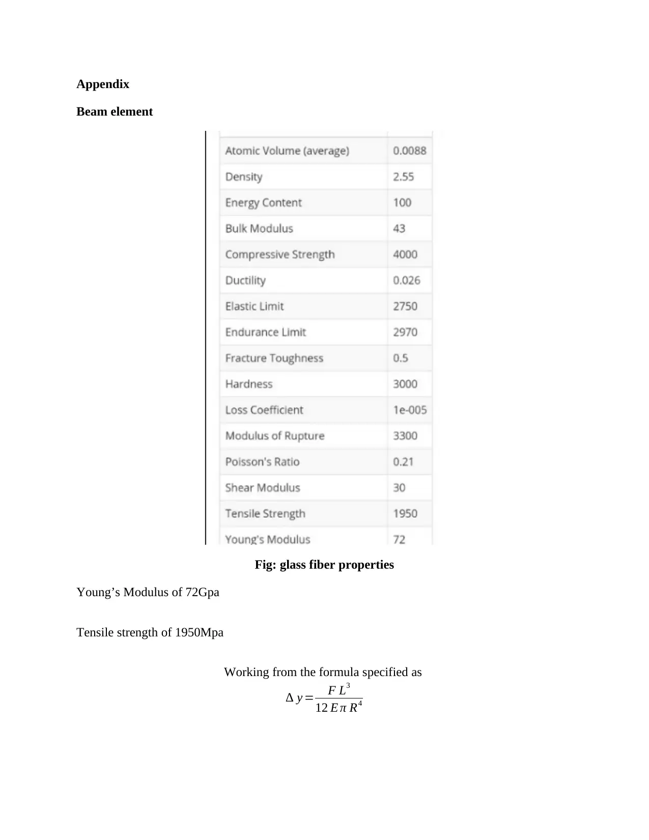
Appendix
Beam element
Fig: glass fiber properties
Young’s Modulus of 72Gpa
Tensile strength of 1950Mpa
Working from the formula specified as
∆ y = F L3
12 E π R4
Beam element
Fig: glass fiber properties
Young’s Modulus of 72Gpa
Tensile strength of 1950Mpa
Working from the formula specified as
∆ y = F L3
12 E π R4
Paraphrase This Document
Need a fresh take? Get an instant paraphrase of this document with our AI Paraphraser
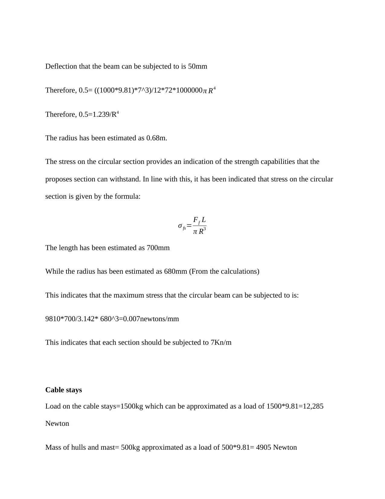
Deflection that the beam can be subjected to is 50mm
Therefore, 0.5= ((1000*9.81)*7^3)/12*72*1000000 π R4
Therefore, 0.5=1.239/R4
The radius has been estimated as 0.68m.
The stress on the circular section provides an indication of the strength capabilities that the
proposes section can withstand. In line with this, it has been indicated that stress on the circular
section is given by the formula:
σ fs= Ff L
π R3
The length has been estimated as 700mm
While the radius has been estimated as 680mm (From the calculations)
This indicates that the maximum stress that the circular beam can be subjected to is:
9810*700/3.142* 680^3=0.007newtons/mm
This indicates that each section should be subjected to 7Kn/m
Cable stays
Load on the cable stays=1500kg which can be approximated as a load of 1500*9.81=12,285
Newton
Mass of hulls and mast= 500kg approximated as a load of 500*9.81= 4905 Newton
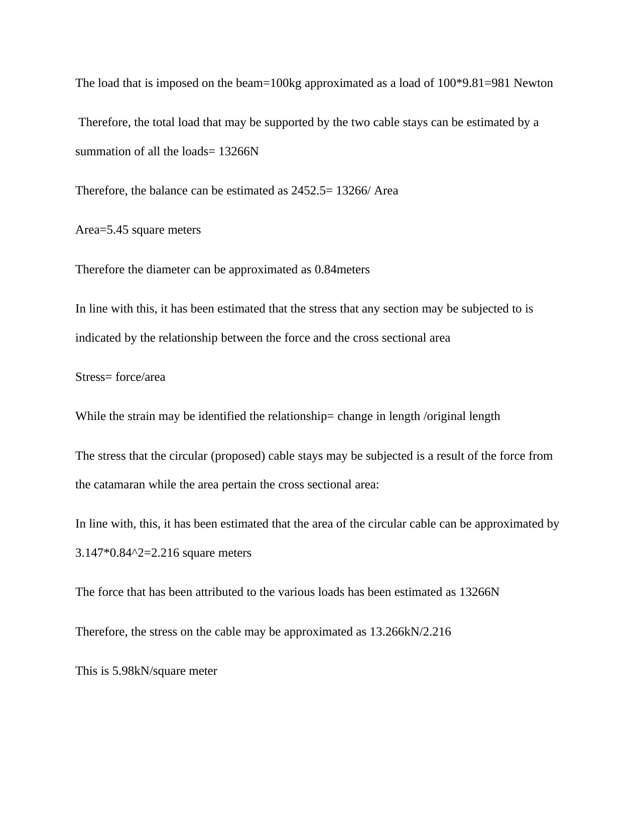
The load that is imposed on the beam=100kg approximated as a load of 100*9.81=981 Newton
Therefore, the total load that may be supported by the two cable stays can be estimated by a
summation of all the loads= 13266N
Therefore, the balance can be estimated as 2452.5= 13266/ Area
Area=5.45 square meters
Therefore the diameter can be approximated as 0.84meters
In line with this, it has been estimated that the stress that any section may be subjected to is
indicated by the relationship between the force and the cross sectional area
Stress= force/area
While the strain may be identified the relationship= change in length /original length
The stress that the circular (proposed) cable stays may be subjected is a result of the force from
the catamaran while the area pertain the cross sectional area:
In line with, this, it has been estimated that the area of the circular cable can be approximated by
3.147*0.84^2=2.216 square meters
The force that has been attributed to the various loads has been estimated as 13266N
Therefore, the stress on the cable may be approximated as 13.266kN/2.216
This is 5.98kN/square meter
⊘ This is a preview!⊘
Do you want full access?
Subscribe today to unlock all pages.
Trusted by 1+ million students worldwide
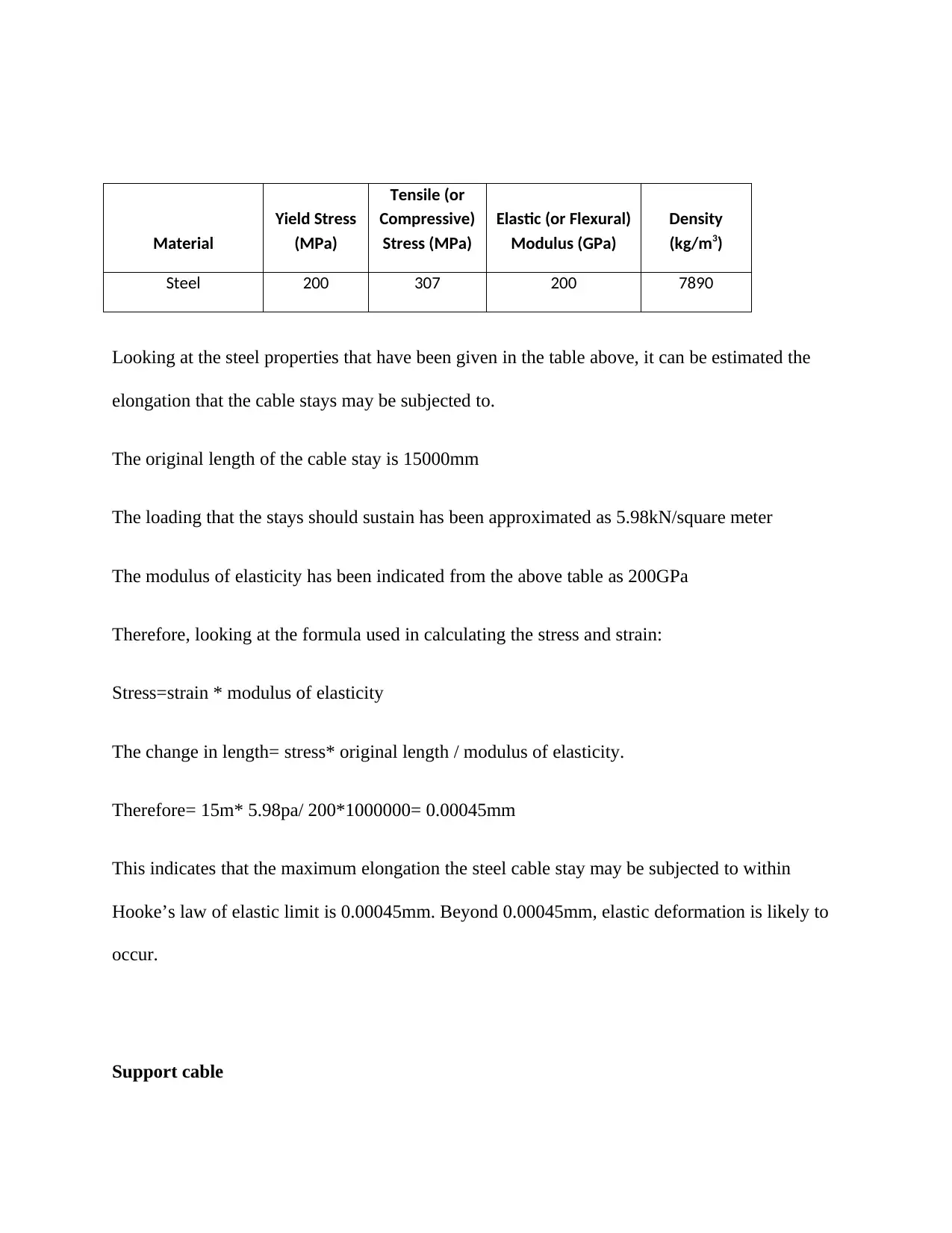
Looking at the steel properties that have been given in the table above, it can be estimated the
elongation that the cable stays may be subjected to.
The original length of the cable stay is 15000mm
The loading that the stays should sustain has been approximated as 5.98kN/square meter
The modulus of elasticity has been indicated from the above table as 200GPa
Therefore, looking at the formula used in calculating the stress and strain:
Stress=strain * modulus of elasticity
The change in length= stress* original length / modulus of elasticity.
Therefore= 15m* 5.98pa/ 200*1000000= 0.00045mm
This indicates that the maximum elongation the steel cable stay may be subjected to within
Hooke’s law of elastic limit is 0.00045mm. Beyond 0.00045mm, elastic deformation is likely to
occur.
Support cable
Material
Yield Stress
(MPa)
Tensile (or
Compressive)
Stress (MPa)
Elastic (or Flexural)
Modulus (GPa)
Density
(kg/m3)
Steel 200 307 200 7890
Paraphrase This Document
Need a fresh take? Get an instant paraphrase of this document with our AI Paraphraser
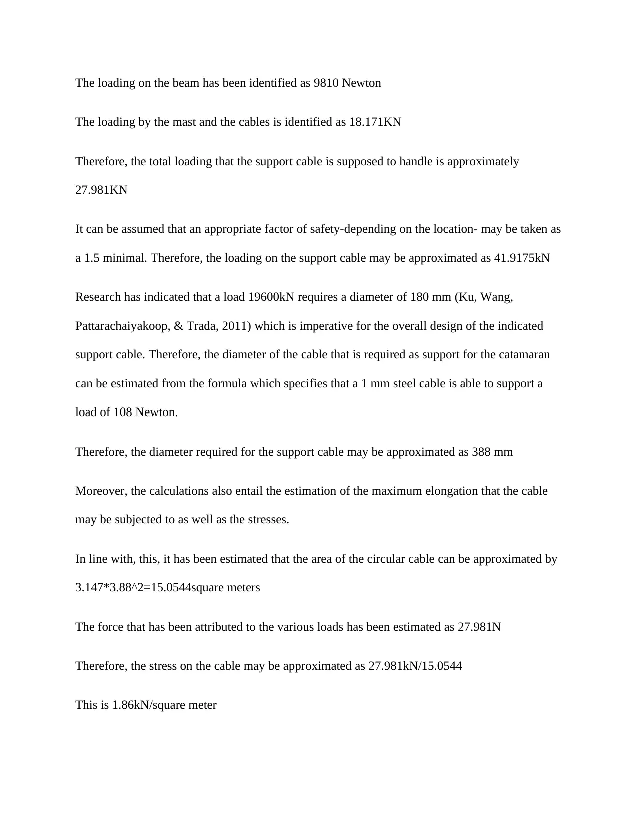
The loading on the beam has been identified as 9810 Newton
The loading by the mast and the cables is identified as 18.171KN
Therefore, the total loading that the support cable is supposed to handle is approximately
27.981KN
It can be assumed that an appropriate factor of safety-depending on the location- may be taken as
a 1.5 minimal. Therefore, the loading on the support cable may be approximated as 41.9175kN
Research has indicated that a load 19600kN requires a diameter of 180 mm (Ku, Wang,
Pattarachaiyakoop, & Trada, 2011) which is imperative for the overall design of the indicated
support cable. Therefore, the diameter of the cable that is required as support for the catamaran
can be estimated from the formula which specifies that a 1 mm steel cable is able to support a
load of 108 Newton.
Therefore, the diameter required for the support cable may be approximated as 388 mm
Moreover, the calculations also entail the estimation of the maximum elongation that the cable
may be subjected to as well as the stresses.
In line with, this, it has been estimated that the area of the circular cable can be approximated by
3.147*3.88^2=15.0544square meters
The force that has been attributed to the various loads has been estimated as 27.981N
Therefore, the stress on the cable may be approximated as 27.981kN/15.0544
This is 1.86kN/square meter
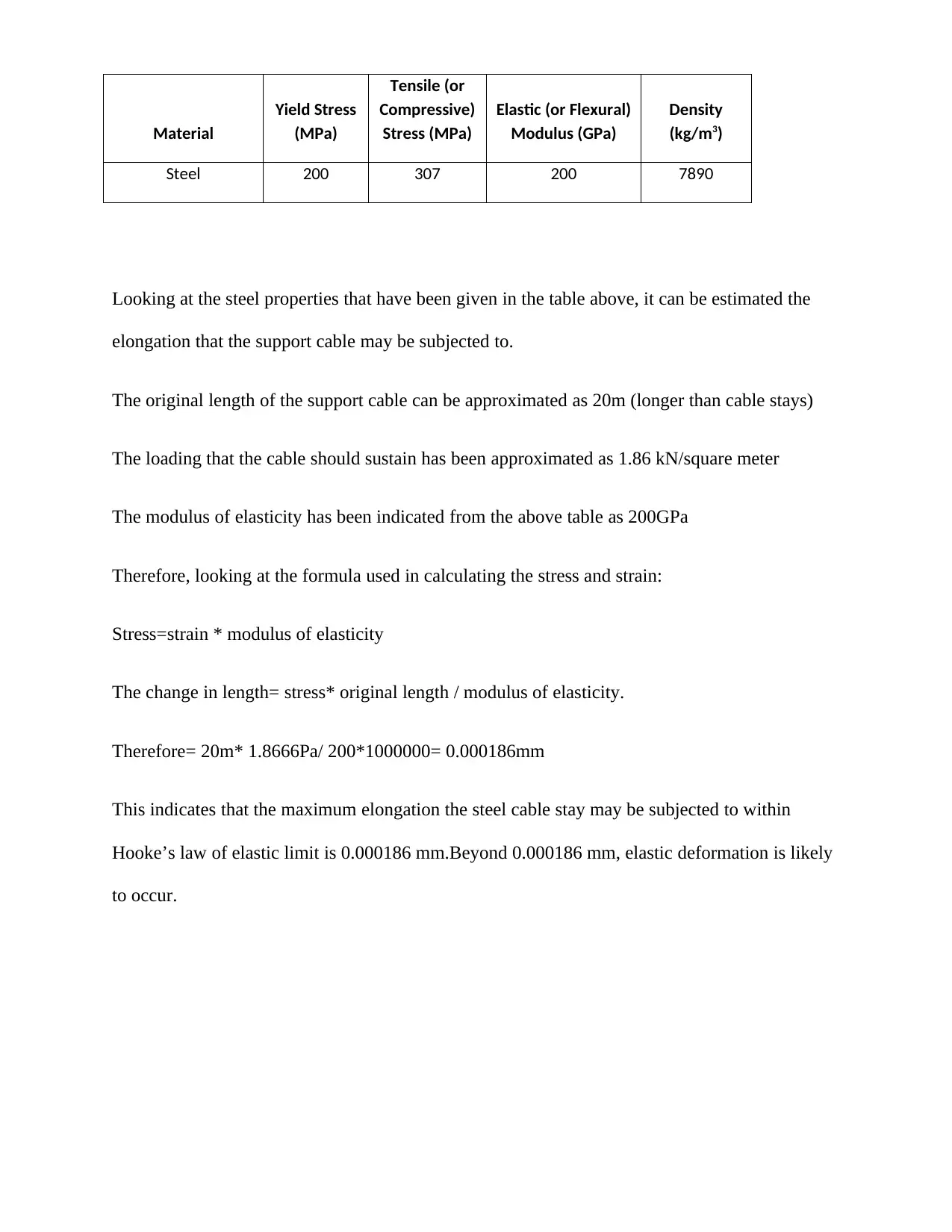
Looking at the steel properties that have been given in the table above, it can be estimated the
elongation that the support cable may be subjected to.
The original length of the support cable can be approximated as 20m (longer than cable stays)
The loading that the cable should sustain has been approximated as 1.86 kN/square meter
The modulus of elasticity has been indicated from the above table as 200GPa
Therefore, looking at the formula used in calculating the stress and strain:
Stress=strain * modulus of elasticity
The change in length= stress* original length / modulus of elasticity.
Therefore= 20m* 1.8666Pa/ 200*1000000= 0.000186mm
This indicates that the maximum elongation the steel cable stay may be subjected to within
Hooke’s law of elastic limit is 0.000186 mm.Beyond 0.000186 mm, elastic deformation is likely
to occur.
Material
Yield Stress
(MPa)
Tensile (or
Compressive)
Stress (MPa)
Elastic (or Flexural)
Modulus (GPa)
Density
(kg/m3)
Steel 200 307 200 7890
⊘ This is a preview!⊘
Do you want full access?
Subscribe today to unlock all pages.
Trusted by 1+ million students worldwide
1 out of 14

Your All-in-One AI-Powered Toolkit for Academic Success.
+13062052269
info@desklib.com
Available 24*7 on WhatsApp / Email
![[object Object]](/_next/static/media/star-bottom.7253800d.svg)
Unlock your academic potential
Copyright © 2020–2026 A2Z Services. All Rights Reserved. Developed and managed by ZUCOL.