Cellular Wireless Communication: Network Design and Traffic Management
VerifiedAdded on 2023/01/11
|14
|3053
|59
Report
AI Summary
This report delves into the intricacies of cellular wireless communication. It begins by defining cell splitting, a crucial technique for enhancing capacity in densely populated areas, and differentiates between permanent and dynamic splitting methods. The report then proceeds to calculate the reuse distance and number of channels, along with Erlang values to assess traffic load. The core of the report is a detailed cellular network design, outlining the strategic placement of base stations, mobile switching centers, and the implementation of frequency reuse to optimize network performance. The design emphasizes the importance of base station site selection, antenna configurations, and traffic management through dynamic channel allocation, concluding with a discussion on the Erlangs IDEAL Grading model. The report aims to optimize network bandwidth, proper positioning of cellular network elements, and setting up several base stations in each cell for faster signal transmission. The design also covers the base station site location, mobile switching center, frequency re-use, cellular network traffic management and the cellular model.
Cellular wireless communication 1
Cellular Wireless Communication
Name
Institution
Cellular Wireless Communication
Name
Institution
Paraphrase This Document
Need a fresh take? Get an instant paraphrase of this document with our AI Paraphraser
Cellular wireless communication 2
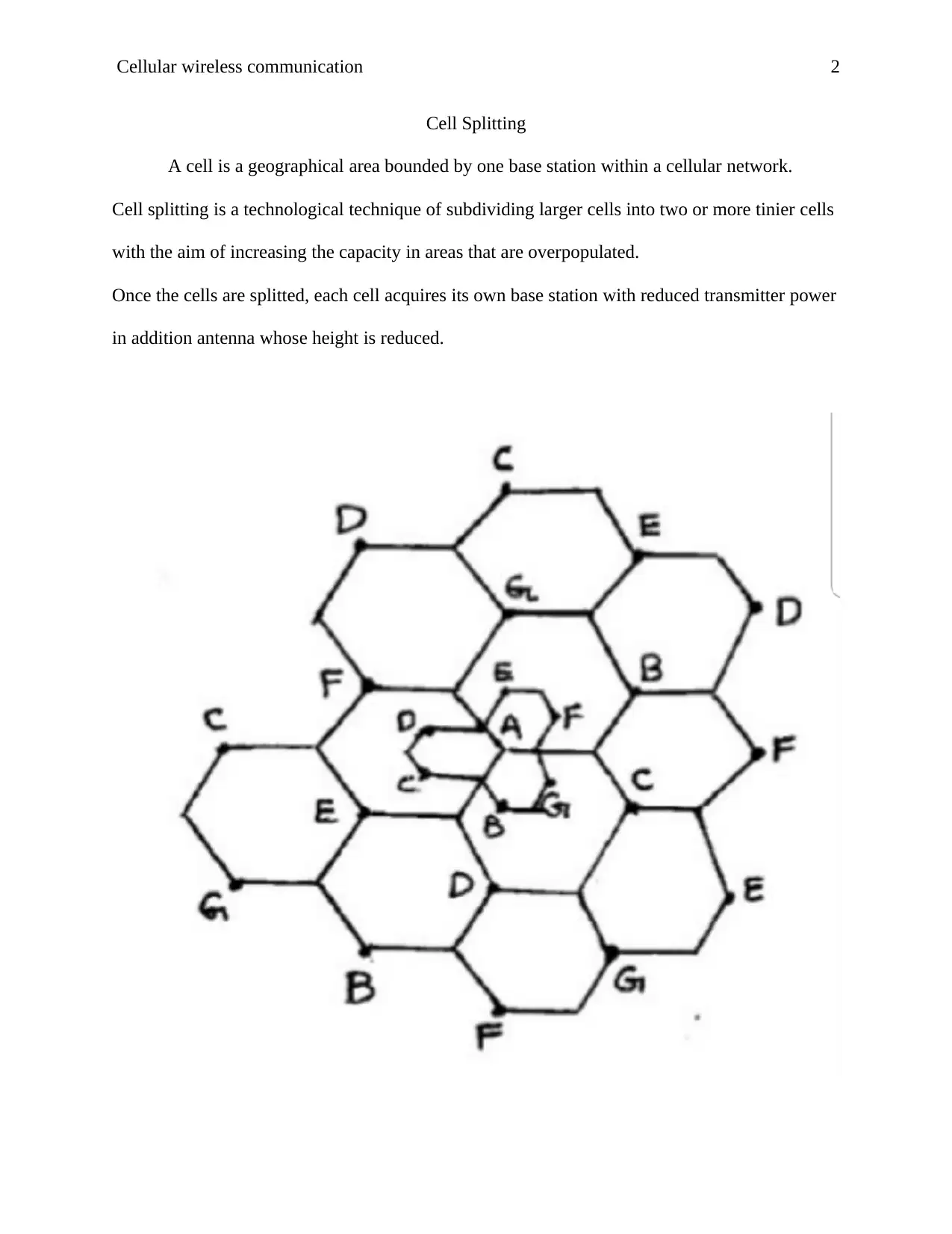
Cell Splitting
A cell is a geographical area bounded by one base station within a cellular network.
Cell splitting is a technological technique of subdividing larger cells into two or more tinier cells
with the aim of increasing the capacity in areas that are overpopulated.
Once the cells are splitted, each cell acquires its own base station with reduced transmitter power
in addition antenna whose height is reduced.
Cellular wireless communication 3
Types of cell splitting
Beginning with Permanent splitting
Refers to a kind of cell splitting to which the new cells that are to be split are planned before
the time with much consideration of transmitted power, number of channels, traffic load,
assigned frequencies and cell site selection. The assignment of frequency follows the principles
based on frequency reuse distance ratio.
1. Dynamic splitting
This is a cell splitting technique based on allocated spectrum efficiency in real time
utilization and therefore cell splitting progresses gradually to prevent dropped calls
through the cellular operating system.
Factors that affect cell splitting
I. The radio aspect
Cell size is dependent on the structure of the coverage pattern and how well the
location of the user of the cell is to be known through the usage of the network.
II. The capacity of the switching processor
The smaller the size of the cell results into occurrence of more hand offs as
splitting process continues.
QUESTION 2
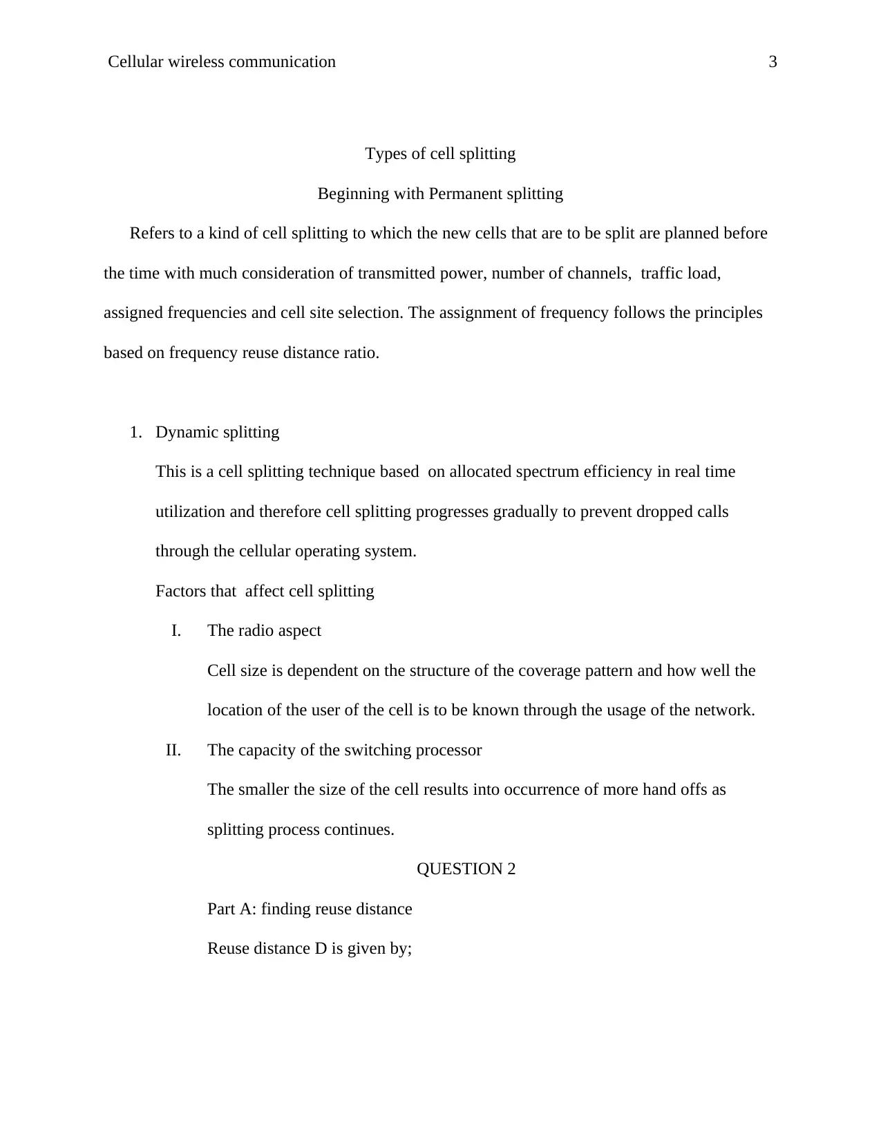
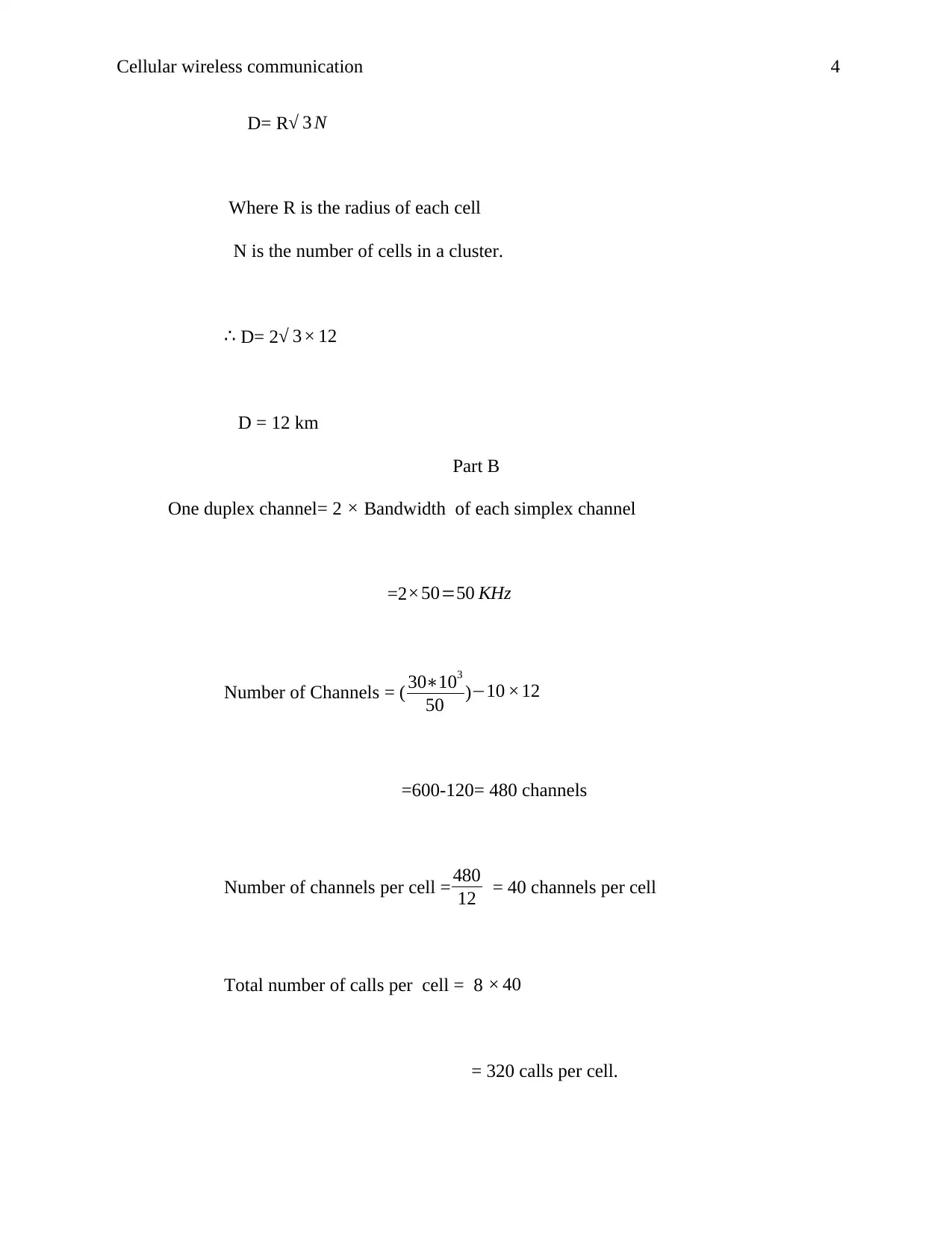
Part A: finding reuse distance
Reuse distance D is given by;
Types of cell splitting
Beginning with Permanent splitting
Refers to a kind of cell splitting to which the new cells that are to be split are planned before
the time with much consideration of transmitted power, number of channels, traffic load,
assigned frequencies and cell site selection. The assignment of frequency follows the principles
based on frequency reuse distance ratio.
1. Dynamic splitting
This is a cell splitting technique based on allocated spectrum efficiency in real time
utilization and therefore cell splitting progresses gradually to prevent dropped calls
through the cellular operating system.
Factors that affect cell splitting
I. The radio aspect
Cell size is dependent on the structure of the coverage pattern and how well the
location of the user of the cell is to be known through the usage of the network.
II. The capacity of the switching processor
The smaller the size of the cell results into occurrence of more hand offs as
splitting process continues.
QUESTION 2
Part A: finding reuse distance
Reuse distance D is given by;
⊘ This is a preview!⊘
Do you want full access?
Subscribe today to unlock all pages.
Trusted by 1+ million students worldwide
Cellular wireless communication 4
D= R√ 3 N
Where R is the radius of each cell
N is the number of cells in a cluster.
∴ D= 2√ 3× 12
D = 12 km
Part B
One duplex channel= 2 × Bandwidth of each simplex channel
=2 ×50=50 KHz
Number of Channels = ( 30∗103
50 )−10 ×12
=600-120= 480 channels
Number of channels per cell = 480
12 = 40 channels per cell
Total number of calls per cell = 8 × 40
= 320 calls per cell.
Paraphrase This Document
Need a fresh take? Get an instant paraphrase of this document with our AI Paraphraser
Cellular wireless communication 5
If each user keeps the traffic channel busy for an average of 5% time and an average of
60 requests per hour are generated, what is the Erlang value?
Average number of request made/sec= λ = 60
3600
= 1
60 requests/sec
Average duration of calls = T = 5% of 1 hour = 5
100 ×3600 sec
= 180 sec
Erlang value = A = λ ×T = 1
60 × 180
= 3 Erlangs
Question 3.
Part A: Cellular network design.
Basic structure
Cellular wireless communication 6
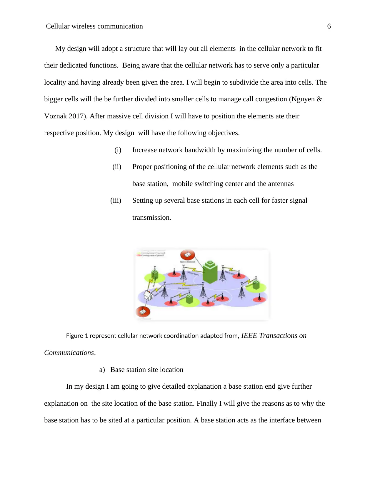
My design will adopt a structure that will lay out all elements in the cellular network to fit
their dedicated functions. Being aware that the cellular network has to serve only a particular
locality and having already been given the area. I will begin to subdivide the area into cells. The
bigger cells will the be further divided into smaller cells to manage call congestion (Nguyen &
Voznak 2017). After massive cell division I will have to position the elements ate their
respective position. My design will have the following objectives.
(i) Increase network bandwidth by maximizing the number of cells.
(ii) Proper positioning of the cellular network elements such as the
base station, mobile switching center and the antennas
(iii) Setting up several base stations in each cell for faster signal
transmission.
Figure 1 represent cellular network coordination adapted from, IEEE Transactions on
Communications.
a) Base station site location
In my design I am going to give detailed explanation a base station end give further
explanation on the site location of the base station. Finally I will give the reasons as to why the
base station has to be sited at a particular position. A base station acts as the interface between
⊘ This is a preview!⊘
Do you want full access?
Subscribe today to unlock all pages.
Trusted by 1+ million students worldwide
Cellular wireless communication 7
the traditional wired phones and the wireless phones (Nguyen & Voznak 2017). The base station
will use microwave radio communication to transmit signal. The base station will be mounted on
with several antennas .
The base station antennas will have to be mounted on a tower or any other tall building
within the cellular network region. The reason for mounting the antennas to such raised position
is to make it easier for cell phone users to communicate faster and efficient. From such raised
position , antennas are free from obstacles such as other buildings, Tall tree or hill that can
distract the flow of signals. The actual antenna that has to be used in this kind of cellular
network should be less than ten centimeters in height. The antennas will be grouped into cluster
with a common height and then mounted on the building (Zhou, Gui & Xiong 2017).
According to my design for the bellow cellular network which depicts an urban center.
The bigger cells will be subdivided into smaller cells in order to manage cell call congestion.
Then each cell will be divided into three sectors. Each sector will have an antenna rack. The
antenna rack will acquire a triangular shape. Each face of the antenna rack will be installed three
antennas. Among the three antennas, one will be for transmitting signals while the other antennas
two are for receiving signals (Deng et al. 2019).. The two receiving signals will on the receive
side whereby the base station can compare and contrast between the two antenna and finally
select the best antenna to be used by each user in the cell. The cellular tower meant to transmit
antennas will be located in between the two receiving antennas.
The physical size of each antenna will be determined by the frequency of the
operation. If we shall chose to use the frequency of say 450MHz , then I will have to stick to
Paraphrase This Document
Need a fresh take? Get an instant paraphrase of this document with our AI Paraphraser
Cellular wireless communication 8
antennas of about 4M height. Keeping in mind that there exist two types of antennas , that is
Omnidirectional and Sector antenna. Omnidirectional antennas are mostly used in areas with
cellular network that has low traffic. On the other hand Sector antenna are well adapted to area
that encounters very high traffic flow of cellular calls. Therefore the design of this particular
network prefer to use Sector antenna since the area is an urban center and is likely to have high
population which entirely lead to high traffic (Chen et al. 2017).
Orakzai, Iqbal, Naeem & Ahmad (2018), further argue that Since the area to install this
kind of a network is an urban center with record a higher number of calls, the base station to used
will require to have a very powerful transmitting amplifier which can comfortably generate
strong signal at ease. Therefore this powerful power amplifier will or is to be linked up to the
antenna used to transmit signals via a lengthy coaxial cable. The low now-noise amplifiers will
then connect the coaxial cable to the receiving antenna. The low noise amplifier have the ability
to detect incoming weak signal and separate it from environmental background noise.
Within the base station their shall exist a base station controller. The controller is a
computer that will be monitoring and controlling operations within the cell network automat call
without supervision. Also within the base station their exist an AC/DC rectification system. The
system will serve to convert the incoming AC power from the supply to DC power needed to
power the electronic circuit within the network. The base station should also have a backup DC
power system to provide a faster alternative option whenever AC power fails automatically.
b) Mobile switching center
Cellular wireless communication 9
Mobile switching center is the centerpiece that joins up and manages all components
within a cellular network. The MSc acts as a switch to control the calls within the cell. In the
design of the network stated. I will have one mobile switching center that will be connect ion
point for the entire network (Waqas et al. 2018).
The MSC will be located in the Mobile Telephone Switching Office (MTSO)at the
center of the area under network coverage. The MTSO will contain all the switching equipment
that controls all the cell sites. In simple terms The MTSO serves as the heart of the cellular
system. MSC will be responsible for the task of interconnecting calls within the cellular
network. The MSC will be situated at point where its signal can reach the nearby Public
Switched Telephone Network (PSTN) . This will help to link up the cellular network to other
public networks.
MSC in this particular network will have duplicated circuits as well as many back up
to ensure maximum performance despite failures. In this cellular network,
c) Frequency Re-use
Within this cellular network, Frequency reuse will be archived by taking the subset of
total number of channels available and assigning to the base station. In addition to power output
of the transmitter. By doing this I will ensure that the cellular network increases the number of
available channels to the users. Each cell within the network will be allocated a certain portion
of the overall frequency spectrum (Singh & Singh 2019).. Different user will be permitted to use
the channel allocated to their cell. However different cells which are separated by re-use
distance , D, can access and use a common channel without making any interference to their
respective cell radius. Cell radius is the distance between the center of the cell and the
⊘ This is a preview!⊘
Do you want full access?
Subscribe today to unlock all pages.
Trusted by 1+ million students worldwide
Cellular wireless communication 10
circumference of the ell. Therefore the re-use distance from the above parameters will be
calculated as;
D= R√ 3 N where N number of cells in a cluster.
d) Cellular network traffic management
Keeping in mind awareness of high number of customer within the cellular network, a
better way of channel allocation has to be adopted in order to manage cell traffic. I will therefor
use the Dynamic Channel Allocation to control traffic flow within the network. Each cell within
the allocated network will be allocated a certain portion of the overall frequency spectrum.
Different user will be permitted to use the channel allocated to their cell. Based on the research
done by Orakzai, Iqbal, Naeem & Ahmad (2018), however different cells which are separated
by re-use distance , D, can access and use a common channel without making any interference to
their respective cell radius. Cell radius is the distance between the center of the cell and the
circumference of the cell (Fan, Tian, Jiang & Vasilakos, 2018).
Dynamic allocation will be dealing with the allocation of channels to cells. Each user is
permitted to utilize the channel of a cell as he/she moves in the cell. Channel allocation is
therefore factored worth the reuse distance. With dynamic channel, when a cell wants to take a
call, it makes a selection from a list of channels available using cost criteria.
e) Cellular model
Trigui& Affes (2019), asserts that the model to be used here will therefore have to
comply with the structure of the cellular network. My proposed design can well be supported
when I use the model of Erlangs IDEAL Grading. The model will have differentiated availability
and multiservice traffic. The chosen model will be advantageous to the design such that it’s a
Paraphrase This Document
Need a fresh take? Get an instant paraphrase of this document with our AI Paraphraser
Cellular wireless communication 11
kind of simplified model that can eliminate the parameters of overflow traffic. According to my
design, the calculation of the overflow in the system can be reduced to calculation in a system
with a single grading
The design approach that I have generated is the best to go after much consideration to
the area under coverage. If the plan is well followed and the network being laid as per the
information above , then most of the parameter used such as the bandwidth can be fully utilized
as well as frequency. The diagram given in the question is cellular architecture which shows a
certain geographical location whose cells have to be split into many tiny cells. The main
objective of this kind of design is to save on cost of inputs as well as the cost of call
management within the system. The design is also structure in that manner in order to minimize
traffic overflow and allow wider coverage and to minimize the consumption of power.
Part B: Reasons for designing the above structure
The diagram shown is a cellular architecture which shows a certain geographical location
whose cells have been split. There are a number of reason why cell splitting has been
concentrated most specifically at the center and not on the margin (Zheng, Wang & Yuan 2018).
The main reason is that the area being an urban center which has dense population at the center
that at the outskirt .The main goal of having such a design structure is to save on cost of inputs
as well as the cost of call management within the system. The design is also structure in that
manner in order to minimize on space and allow wider coverage and to minimize power
consumption
Having looked at the area network depicts an urban area. This is evident with the
availability of many cells which are highly congested in especially at the center. Since the area
Cellular wireless communication 12
to install this kind of a network is an urban center which record a higher number of calls due to
its high population, the base station to be used require to have a very powerful transmitting
amplifier which can comfortably generate strong signal at ease. Therefor this powerful power
amplifier will have be linked up to the antenna used to transmit signals via a lengthy coaxial
cable. The low now-noise amplifiers will then connect the coaxial cable to the receiving
antenna. The low noise amplifier have the ability to detect incoming weak signal and separate it
from environmental background noise.
According to Zheng, Wang & Yuan (2018), they denote that the third reason for having a
structure as the one shown is to easily manage traffic overflow. There are high chances of having
call traffic congestion at the center where there is dense population. Having very many cell at
that particular point makes communication more faster. This can be archived easily bearing in
mind that each cell will have its own base station with several antennas attached to it.
⊘ This is a preview!⊘
Do you want full access?
Subscribe today to unlock all pages.
Trusted by 1+ million students worldwide
1 out of 14
Related Documents


Your All-in-One AI-Powered Toolkit for Academic Success.
+13062052269
info@desklib.com
Available 24*7 on WhatsApp / Email
![[object Object]](/_next/static/media/star-bottom.7253800d.svg)
Unlock your academic potential
Copyright © 2020–2026 A2Z Services. All Rights Reserved. Developed and managed by ZUCOL.