Analysis of Central Heating Control System V10 - ITECH7410 Project

Verified

Added on  2023/06/10

|18
|3351
|481
Project
AI Summary
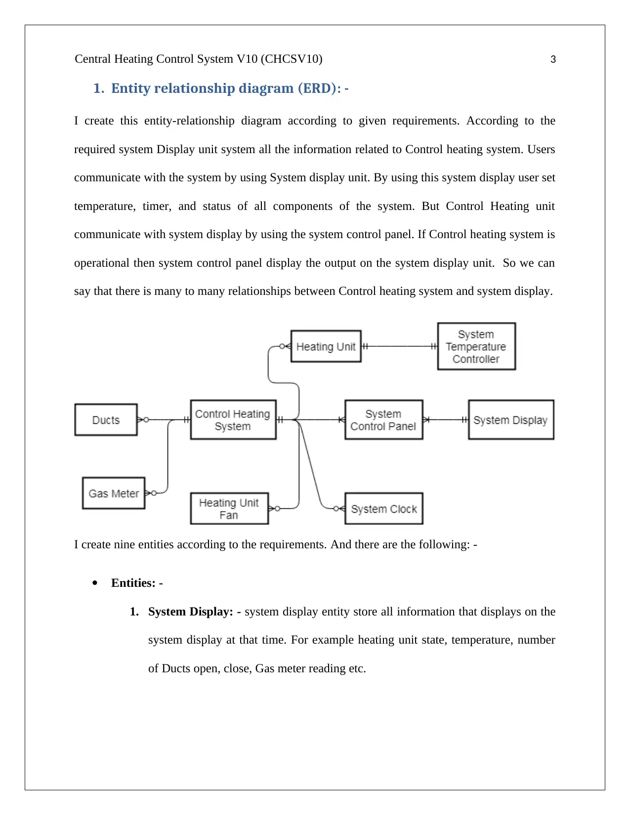
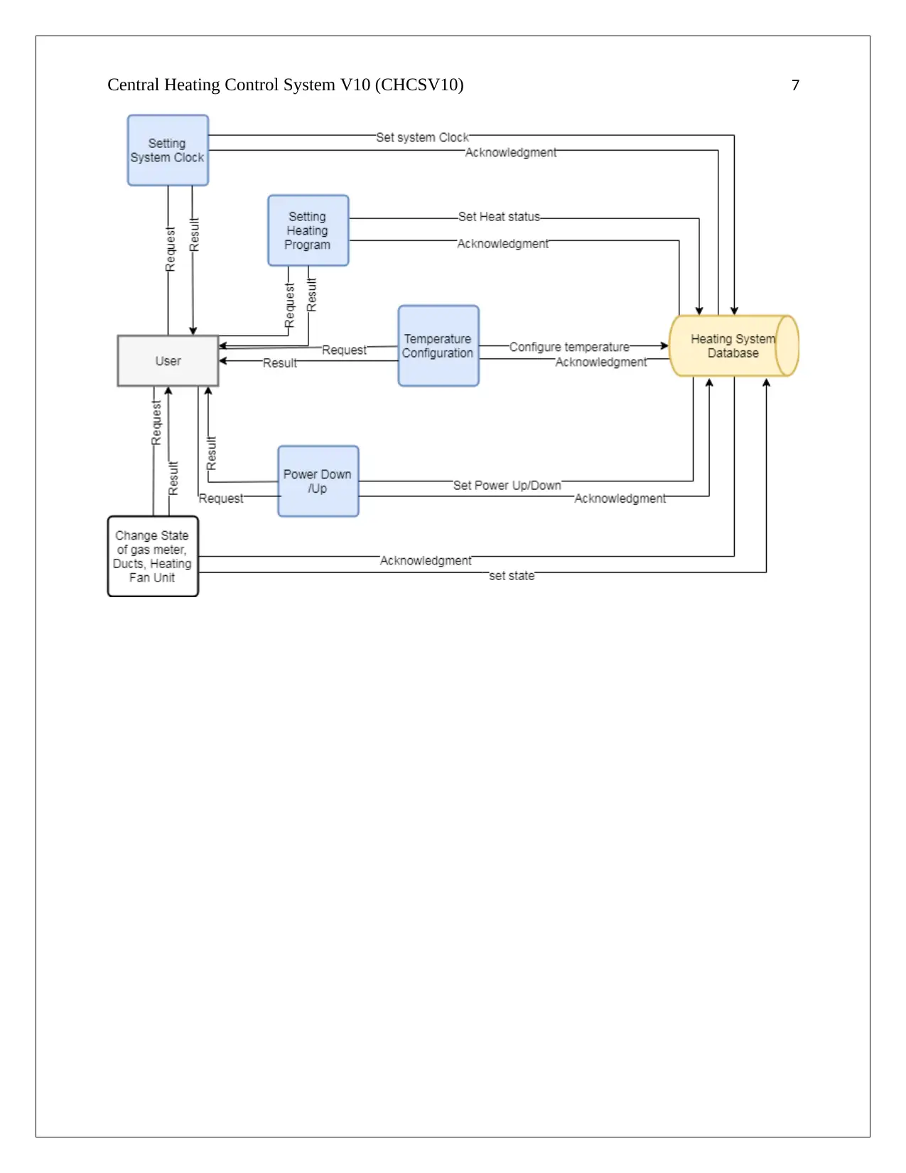
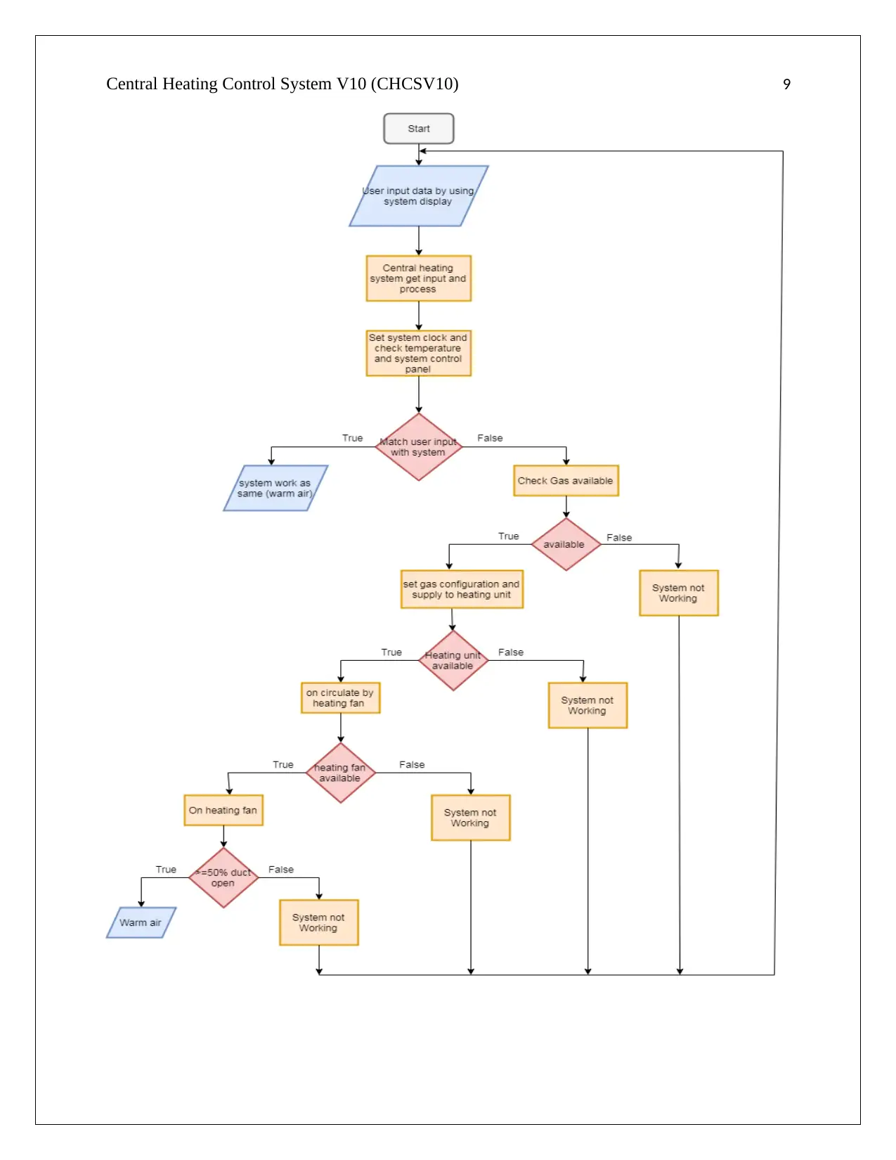
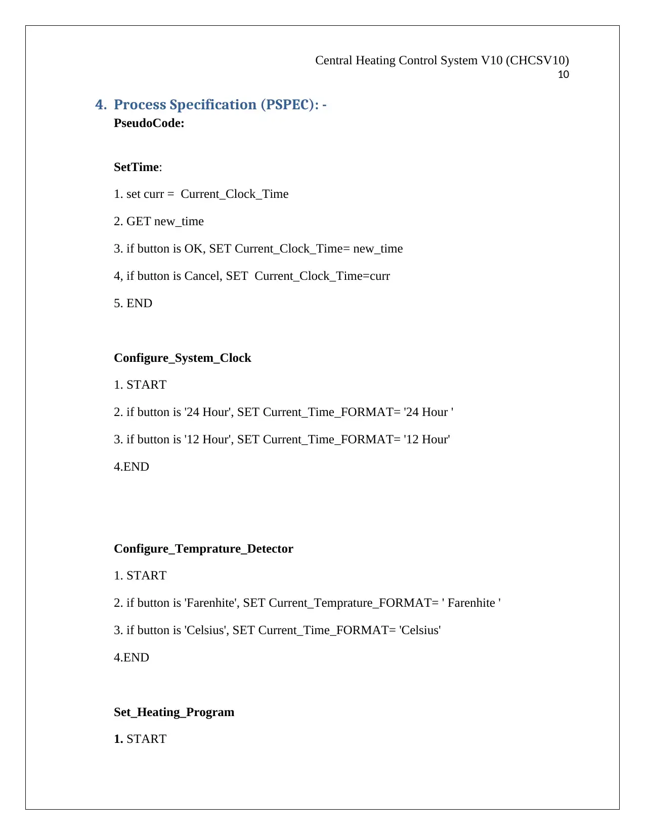
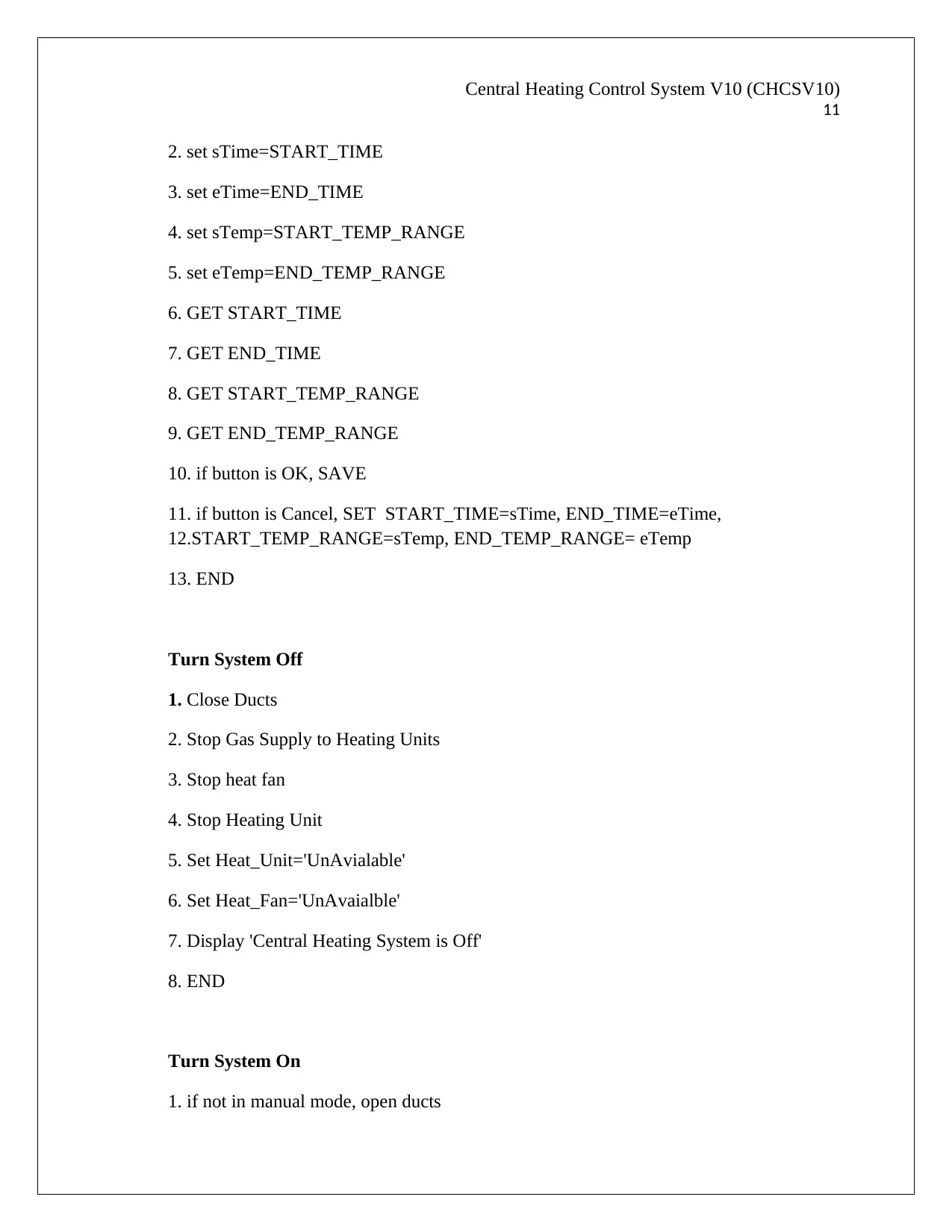
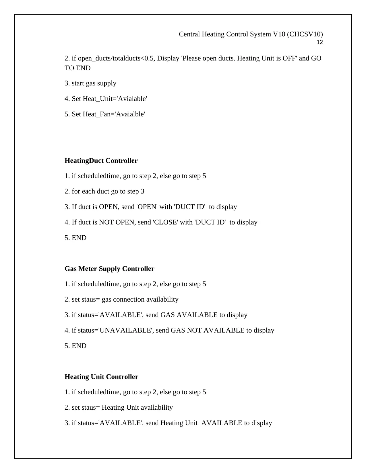
This assignment provides a comprehensive analysis of the Central Heating Control System V10 (CHCSV10), a real-time system. The analysis includes an Entity Relationship Diagram (ERD) detailing nine entities such as System Display, System Control Panel, and Control Heating System, illustrating their relationships. A Data Flow Diagram (DFD) outlines the data flow, with processes such as Setting System Clock, Setting Heating Program, and Temperature Configuration. A Control Flow Diagram (CFD) visualizes the control flow within the system, showing the sequence of operations based on user inputs and system conditions. Process Specifications (PSPEC) are provided using pseudocode for various functions like SetTime, Configure_System_Clock, and Turn System On/Off. Control Specifications (CSPEC) include a Process Activation table and descriptions of controllers for different system components (Gas Meter, Heating Unit, etc.). The document covers the system's functionality, from user interaction to the control of heating elements, ensuring that the system responds to external events within a defined time interval, as required for real-time systems.
Document Page
Central Heating Control System V10 (CHCSV10) 1
Central Heating
Control System V10
(CHCSV10)
Student id: -
Student name: -
Date: -
tabler-icon-diamond-filled.svg

Paraphrase This Document

Need a fresh take? Get an instant paraphrase of this document with our AI Paraphraser
Document Page
Central Heating Control System V10 (CHCSV10) 2
Table of contents
1. Entity relationship diagram (ERD) ………………………………………………………………………………………….3
2. Data Flow diagram (DFD) ………………………………………………………………………………………………………6
3. Control Flow Diagram (CFD) …………………………………………………………………………………………………..8
4. Process Specification (PSPEC)……………………………………………………………………………………………….10
5. Control Specification (CSPEC) ……………………………………………………………………………………………...15
5.1 Process Activation table ………………………………………………………………………………………….…..15
5.2 State Machine Diagram (SMD) ……………………………………………………………………………………..15
6. Data dictionary ……………………………………………………………………………………………………………………16
7. Bibliography ………………………………………………………………………………………………………………………….17
Document Page
Central Heating Control System V10 (CHCSV10) 3
1. Entity relationship diagram (ERD): -
I create this entity-relationship diagram according to given requirements. According to the
required system Display unit system all the information related to Control heating system. Users
communicate with the system by using System display unit. By using this system display user set
temperature, timer, and status of all components of the system. But Control Heating unit
communicate with system display by using the system control panel. If Control heating system is
operational then system control panel display the output on the system display unit. So we can
say that there is many to many relationships between Control heating system and system display.
I create nine entities according to the requirements. And there are the following: -
ï‚· Entities: -
1. System Display: - system display entity store all information that displays on the
system display at that time. For example heating unit state, temperature, number
of Ducts open, close, Gas meter reading etc.
Document Page
Central Heating Control System V10 (CHCSV10) 4
2. System Control Panel: - system control panel store information system display
and control heating system. It means that this entity store foreign key of system
display entity and Control Heating System.
3. Control Heating System:- Control Unit entity store all information of heating
unit, system temperature controller, Ducts, gas meter, heating unit fan and the
system clock. It means that this entity store all foreign keys of heating unit entity,
Ducts entity, Gas Meter entity, Heating Unit Fan entity and System Clock entity.
4. Heating Unit: - Heating Unit entity store information different heating unit
number, heating capacity, state, operating/not- operating etc.
5. System Temperature Controller: - System Temperature Controller entity store
information related to Heating Unit Temperature. Because it is a process of the
heating unit.
6. Ducts: - Ducts entity store information related to each Duct, state of duct etc.
7. Gas meter: - Gas meter entity store information related to the state of the gas
meter, gas meter reading, operating/ not- operating etc.
8. Heating Unit Fan: - Heating Unit Fan entity store information related to each
heating fan, state of the heating fan, operating/ not- operating etc.
9. System Clock: - System Clock entity store information related to date, time, the
day of the week, the vital component in the real-time actions of the system.
ï‚· The relationship between entities: -
1. 1: 1 relationship between Heating Unit and System Temperature Control entities. A
Heating Unit System has one and only one System Temperature Control and each
System Temperature Control has one and only one Heating Unit System.
tabler-icon-diamond-filled.svg

Paraphrase This Document

Need a fresh take? Get an instant paraphrase of this document with our AI Paraphraser
Document Page
Central Heating Control System V10 (CHCSV10) 5
2. 1: M relationship between System Display and System Control Panel entities. a
System Display has one or many System Control Panel but each System Control
Panel has one and only one System Display.
3. 1: M relationship between Central Heating System and System Control Unit entity. A
Central Heating System has one or many System Control Unit but each System
Control unit has one and only one Central Heating System.
4. 1: M relationship between Central Heating System and Heating unit entity. A Central
Heating System has one or many Heating Unit but each Heating Unit has one and
only one Central Heating System.
5. 1: M relationship between Central Heating System and System Clock entity. A
Central Heating System has one or many system Clock but each System Clock has
one and only one Central Heating System.
6. 1: M relationship between Central Heating System and Heating Unit Fan entity. A
Central Heating System has one or many Heating Unit Fan but each Heating Unit Fan
has one and only one Central Heating System.
7. 1: M relationship between Central Heating System and Gas Meter entity. A Central
Heating System has one or many Gas Meter but each Gas Meter has one and only one
Central Heating System.
8. 1: M relationship between Central Heating System and Ducts entity. A Central
Heating System has one or many Ducts but each Duct has one and only one Central
Heating System.
Document Page
Central Heating Control System V10 (CHCSV10) 6
2. Data flow diagram (DFD): -
This data flow diagram creates according to system requirements. In this diagram Heating
System Database store all the database of the Central heating system. Here only one external
entity that is the user. The only the user can communicate with this system. In this diagram, I
create four processes and there are the following: -
1. Setting System Clock: - in this process firstly user send the request to the Central
heating system to set the system clock. Then Central heating system accepts the request
and set the system clock according to user requirement and display the result on the
system display. The user can set day of the week, date, time timer etc. in this process.
2. Setting Heating Program: - in this process user sends a request to the central heating
system to set the heating program. The system accepts the user request and set heat
according to user requirement and display result on the system display.
3. Temperature Configuration: - in this process, the user sends a request to the central
heating system to set and configure the temperature. The central heating system accepts
the request and set temperature according to user requirement and display output on the
system display.
4. Power Down/ up: - in this process, user sends the request to the central heating system to
Power down/ up the system. The system checks the status and set the command
according to user requirement and gives the result.
5. Change State of gas meter, Ducts, Heating Fan unit: - in this process user request
change state of gas meter/ Ducts/ Heating Fan unit to the central heating system. The
system checks the state and set state according to user requirements and display result on
system display unit.
Document Page
Central Heating Control System V10 (CHCSV10) 7
tabler-icon-diamond-filled.svg

Paraphrase This Document

Need a fresh take? Get an instant paraphrase of this document with our AI Paraphraser
Document Page
Central Heating Control System V10 (CHCSV10) 8
3. Control flow diagram (CFD): -
I create control flow diagram according to case system. This diagram shows the flow to control
of the whole system. Firstly the user gives input to the Central heating system by using the
system display unit. We know that user only communicates with the system display and system
display communicate with the central heating system by system control panel. So that when user
set inputs on system display then that input accept by system display and to system control unit
then that unit sends inputs to the central unit system.
Now the central heating system firstly set the system clock and checks the temperature
specification. If the user input matches with current status to the system then system work as
same and produces ware air. But if user inputs are different as compare to system state then the
system checks gas availability. If gas is not available then stop system and control goes to start
the process. If gas is available then configure the gas flow and check heating unit availability. If
the heating unit not available then stop system working and send control to start the process. If
heating unit available then on the circulation of the heating unit and check heating fan is
available or not. If the heating fan is not available then stop system and control goes to start the
process. But if the heating fan is available then on heat pass by ducts and checks ducts are
>=50% open or not. If ducts are not >=50% open then system stop working and control goes to
starting the process. But if ducts are >=50% open then heating fan produce warm air by using
ducts.
Document Page
Central Heating Control System V10 (CHCSV10) 9
Document Page
Central Heating Control System V10 (CHCSV10)
10
4. Process Specification (PSPEC): -
PseudoCode:
SetTime:
1. set curr = Current_Clock_Time
2. GET new_time
3. if button is OK, SET Current_Clock_Time= new_time
4, if button is Cancel, SET Current_Clock_Time=curr
5. END
Configure_System_Clock
1. START
2. if button is '24 Hour', SET Current_Time_FORMAT= '24 Hour '
3. if button is '12 Hour', SET Current_Time_FORMAT= '12 Hour'
4.END
Configure_Temprature_Detector
1. START
2. if button is 'Farenhite', SET Current_Temprature_FORMAT= ' Farenhite '
3. if button is 'Celsius', SET Current_Time_FORMAT= 'Celsius'
4.END
Set_Heating_Program
1. START
tabler-icon-diamond-filled.svg

Paraphrase This Document

Need a fresh take? Get an instant paraphrase of this document with our AI Paraphraser
Document Page
Central Heating Control System V10 (CHCSV10)
11
2. set sTime=START_TIME
3. set eTime=END_TIME
4. set sTemp=START_TEMP_RANGE
5. set eTemp=END_TEMP_RANGE
6. GET START_TIME
7. GET END_TIME
8. GET START_TEMP_RANGE
9. GET END_TEMP_RANGE
10. if button is OK, SAVE
11. if button is Cancel, SET START_TIME=sTime, END_TIME=eTime,
12.START_TEMP_RANGE=sTemp, END_TEMP_RANGE= eTemp
13. END
Turn System Off
1. Close Ducts
2. Stop Gas Supply to Heating Units
3. Stop heat fan
4. Stop Heating Unit
5. Set Heat_Unit='UnAvialable'
6. Set Heat_Fan='UnAvaialble'
7. Display 'Central Heating System is Off'
8. END
Turn System On
1. if not in manual mode, open ducts
Document Page
Central Heating Control System V10 (CHCSV10)
12
2. if open_ducts/totalducts<0.5, Display 'Please open ducts. Heating Unit is OFF' and GO
TO END
3. start gas supply
4. Set Heat_Unit='Avialable'
5. Set Heat_Fan='Avaialble'
HeatingDuct Controller
1. if scheduledtime, go to step 2, else go to step 5
2. for each duct go to step 3
3. If duct is OPEN, send 'OPEN' with 'DUCT ID' to display
4. If duct is NOT OPEN, send 'CLOSE' with 'DUCT ID' to display
5. END
Gas Meter Supply Controller
1. if scheduledtime, go to step 2, else go to step 5
2. set staus= gas connection availability
3. if status='AVAILABLE', send GAS AVAILABLE to display
4. if status='UNAVAILABLE', send GAS NOT AVAILABLE to display
5. END
Heating Unit Controller
1. if scheduledtime, go to step 2, else go to step 5
2. set staus= Heating Unit availability
3. if status='AVAILABLE', send Heating Unit AVAILABLE to display
chevron_up_icon
1 out of 18
circle_padding
hide_on_mobile
zoom_out_icon
[object Object]