ME 21: Design Optimization on Centrifugal Compressors - Report

Verified

Added on  2022/10/01

|20
|3761
|436
Report
AI Summary
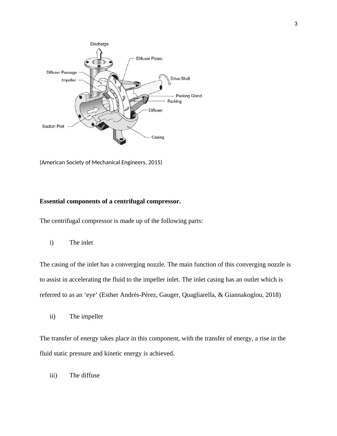
This report provides a comprehensive overview of centrifugal compressors, a crucial component in various engineering applications. It begins with an introduction to centrifugal compressors, highlighting their function in pressure rise and their classification as turbo-compressors. The report details the essential components, including the inlet, impeller, diffuser, and outlet casing, explaining their respective roles in the compression process. It then elucidates the working principle of centrifugal compressors, emphasizing the interplay of centrifugal forces, velocity changes, and pressure increases within the impeller and diffuser. The report further examines the factors influencing compressor performance, underscoring the importance of design optimization, particularly focusing on the impeller. It explores the application of numerical analysis based on 3D Reynolds-averaged Navier-Stokes equations (RANS) for optimization. The construction of centrifugal compressors is also discussed, detailing the casing, impellers, diffuser, and collector. Different types of centrifugal compressors, including single-stage and multi-stage designs, are compared, along with their specific applications, such as compressed air systems, gas turbines, and oil refineries. The merits and demerits of centrifugal compressors are evaluated, followed by a discussion of optimization techniques using the Design of Experiment (DOE) technique to enhance efficiency and performance. This report offers a detailed understanding of centrifugal compressor design, operation, and optimization strategies.
Document Page
1
MECHANICAL ENGINEERING- CENTRIFUGAL COMPRESSOR
By Name
Course
Instructor
Institution
Location
Date
tabler-icon-diamond-filled.svg

Paraphrase This Document

Need a fresh take? Get an instant paraphrase of this document with our AI Paraphraser
Document Page
2
DESIGN OPTIMIZATION ON CENTRIFUGAL COMPRESSOR
Introduction
A centrifugal compressor is one of its class machines in producing pressure rise and is known as
a turbo-compressors. In the centrifugal compressor, the energy is transferred by the dynamic
means from a rotating member (or impeller) to the continuously flowing working fluid
(Braembussche, 2019).
Centrifugal compressor is also referred to as radial compressor and it belongs to a sub-class of
dynamic axisymmetric work –absorbing turbomachinery. The centrifugal compressors
normally achieve pressure rise through the additional of kinetic velocity/ energy to a
continuous flow of fluid through the impeller or rotor. The kinetic energy is in most cases then
converted to increase in potential energy/ static pressure by slowing the flow through a diffuser.
The pressure rise in most cases almost equal to the rise in the diffuser.
Components of a simple centrifugal compressor
The main features of the centrifugal compressor is that the angular momentum of the fluid
which flows through the is partly increased by the virtue of the impeller’s outlet diameter
being larger as compared to the diameter of the inlet (Kim, Samad, & Benini, 2017). The figure
below is an illustration of the main components of a compressor.
Document Page
3
(American Society of Mechanical Engineers, 2015)
Essential components of a centrifugal compressor.
The centrifugal compressor is made up of the following parts:
i) The inlet
The casing of the inlet has a converging nozzle. The main function of this converging nozzle is
to assist in accelerating the fluid to the impeller inlet. The inlet casing has an outlet which is
referred to as an ‘eye’ (Esther Andrés-Pérez, Gauger, Quagliarella, & Giannakoglou, 2018)
ii) The impeller
The transfer of energy takes place in this component, with the transfer of energy, a rise in the
fluid static pressure and kinetic energy is achieved.
iii) The diffuse
Document Page
4
The main function of the diffuse is to convert the high kinetic energy of the fluid present in the
impeller outlet into static pressure.
iv) The outlet casing
The outlet casing is made up of a fluid collector which is also referred to as the scroll or volute.
The working principle of centrifugal compressor
The working principle of a centrifugal compressor is different from the reciprocating or rotary
compressors. When the air passes through the rotating impeller it experiences work or force
which is performed by the centrifugal forces (IMechE., 2014). Normally the work input occurs
when there is an increase in velocity and pressure of the air which flows through the impeller. As
the air flows it loses its velocity the moment it enters the diffuser section. The diffuser is
normally static or fixed element which escorts the air flow the moment it leaves the
impeller. The reduction in speed finally leads to an increase in pressure. The diffuser and the
impeller normally contributes to 35% and 65% of the total pressure which is produced or
developed in the compressor.
The performance of the centrifugal compressor is influenced by a number of factors thus
optimization of the centrifugal compressors can lead to superior design. Identifying the most
essential parameters influencing the performance of the centrifugal compressors greatly assists in
lowering the optimization process and cost of optimization (Amano & Sundén, 2010). The
impeller is the most important components of the centrifugal compressors as far as the design
optimization is concerned. It is very important to take into consideration all the factors which
effects its performance.
tabler-icon-diamond-filled.svg

Paraphrase This Document

Need a fresh take? Get an instant paraphrase of this document with our AI Paraphraser
Document Page
5
In order to achieve a optimize the design of a centrifugal compressor , there is need to make
application of numerical analysis which is based on the 3D Reynolds averaged Navier
equations (RANS) which has been used widely for many decades (Ma, 2016). The application
of the optimization approach based on this analysis will greatly reduce the computational cost
and at the same time help to better predict designs of the turbomachines in order to improve
the overall parameter such as efficiency and the pressure ratio.
In the recent past many design optimization based on the 3D RANS analysis have been
carried out for the turbomachinery blade shape design. The efficiency and reliability of the
centrifugal compressors is very significant especially in the applications to the industrial turbines
and turbochargers (Japikse, 2012). Design optimization of the centrifugal compressors by the use
of Bazier curves have been applied by many researchers. It is possible to define the blade
profile by making application of the Bezier curve parameters for the multi-objective
optimization of pressure efficiency and ratio for an impeller (Esther Andrés-Pérez, Gauger,
Quagliarella, & Giannakoglou, 2018).
Construction of a centrifugal compressor
The construction of a centrifugal compressor generally involves the construction of four
elements namely; inlet, diffusor, collector and impeller
Document Page
6
(American Society of Mechanical Engineers. Fluids Engineering Division. Summer Meeting,
2017)
Casing and inlet
The casing and the inlet are normally guarded or protected by a housing or a casing. The housing
is made up of bearings so as to offer axial and radial support for the rotor. The housing also
comprise a nozzle along with the discharge and inlets flow connection to extract and introduce
flow from the compressor (Aungier, 2011). There are normally two types of casing i.e.;
Vertically split
Horizontally split
The housing or the case is normally constructed with the use of steel or cast iron.
The impellers
Document Page
7
The impellers are mounted or assembled on a steel shaft, the assembly of the impellers and
the steel shaft is known as a compressor rotor (generally in the multi stage compressors)
(Kim, Samad, & Benini, 2017). The rotor offers velocity to the gas with the blades which are
attached to disc which keeps rotating. The blades can be radial, backward-leaning or forward-
leaning depending on the required output. Majority of the multistage compressors makes
application of the backward-leaning blades as they offer high level of efficiency.
Diffuser
The impeller normally extracts the gas with very high velocity into the diffuser passage. The
diffuser normally compromises two walls which forms a radial channel. With these kind of
arrangements the velocity of the gas which flows decreases and the dynamic pressure is also
transformed into static pressure (Von Karman Institute for Fluid Dynamics, 2017). The diffuser
passages are usually a small p-ace which exists between the adjacent diaphragms which
normally turns the gas flow 180o so as to direct the gas towards the next impeller.
Collector
Following the last stage impeller the gas is required to be gathered and then delivered to the
discharge flange. The elements that are used in the collection of the gas that is discharged via the
diffuser is known as the collector (Schobeiri, 2015). This can also be termed as a volute or a
scroll. The collector in some situations it may contain valves and other instrumentation which
are used to control the compressor.
Types of centrifugal compressors
There are two types of compressors i.e.
tabler-icon-diamond-filled.svg

Paraphrase This Document

Need a fresh take? Get an instant paraphrase of this document with our AI Paraphraser
Document Page
8
1. The single stage centrifugal compressor
2. Multi stage centrifugal compressors
The single stage centrifugal compressor
The single stage compressor is made up of only one impeller and it is normally used to
move the gas up to 3 to 1 compression ratio for either vacuum or pressure duty. The single
stage compressor are considered to have an overhung or a beam design arrangement of impellers.
The overhung arrangement of the impellers has the impellers located at the non-driving end of
the shaft (David W. Lewis; Paul E. Allaire; United States. Dept. of Energy; Division of Chemical
Sciences; University of Virginia. Dept. of Mechanical and Aerospace Engineering, 2017). The
main benefit of this kind of arrangement over the multistage compressor is that it offers a
high level of efficiency and the gas which is delivered is free of oil and surge.
The multistage centrifugal compressor
The multistage is made up of 1-10 impellers and they can be arranged in different flow paths
configurations. Throughout each and every stage the compression ratio and temperature are
assumed to be assumed to be constant (City University London, 2013). The multistage
compressor can be arranged in straight-through, compound and double flow configuration.
Multistage compressors are also believed to have a beam type design but the impeller are
located between the radial bearings.
Application of the centrifugal compressor
Document Page
9
The centrifugal compressor has a wide range of applications which includes;
i) Compressed air or gas; the centrifugal compressor are one of the most efficient and
simple way to obtain compressed air (Kidd, 2018). The centrifugal compressor are
best suited when the demand of gas or air is constant and in plenty.
ii) Food security; the food processing industry highly depends on the air compressors
as they can be able to generate oil free compressed air which are necessary for
some sensitive petitions.
iii) Gas turbines: the gas turbines makes application either or both the axial and the
centrifugal compressors to generate the required the necessary compression. The
centrifugal compressors are mainly used in gas turbines as:
Turboshaft
Micro turbines
Turboprop
Auxiliary power Units
iv) Oil refinery, chemical and petrochemical plants: The centrifugal compressors have a
wide application in the oil refinery and related plants. All the above mentioned
application have a split casing and majority of them are multistage compressors
(Boyce, 2017). This type of centrifugal compressors are usually operated by over-
sized steam engines and gas turbines.
v) Air control and Refrigeration; the centrifugal compressors supports a wide range
of thermodynamics and refrigerants, they also have ability to supply compression
in water chiller cycles because of that it has a high demand for application in the
refrigerators and air conditioners.
Document Page
10
Merits of centrifugal compressors
When compared to other types of compressors, the centrifugal compressors are relatively
easy and agile to manufacture (Linden, Fransson, & Cooke, 2010)
The centrifugal compressors are highly reliable and energy efficient since they does not
require any special foundation
They are absolutely oil free in nature since they are made of small number of rubbing
parts
As compared to the axial flow compressor they generate a higher ratio per stage.
Demerits of centrifugal compressors
Centrifugal compressors generates limited amount of pressure and majority of them are
not suitable in applications which require high levels of compression.
When the centrifugal compressors work at relatively high speed a worldly or enlighten
mounting required (Wakabayashi, 2012).
The centrifugal compressors are very sensitive towards problems such as choking and
stalling
Optimization of a Centrifugal Compressor Using the Design of Experiment Technique
The design and optimization of the centrifugal compressor by means of numerical
optimization approach had become one of the main established methods in industries for many
years. In the centrifugal compressors , the impeller plays Avery crucial role in the
performance of the centrifugal compressor and due to that it has gained a lot of interests from
developers and researchers ( American Society of Mechanical Engineers. Aerospace Division,
2015). Good impeller design will bring about will bring about many benefits to the performance
tabler-icon-diamond-filled.svg

Paraphrase This Document

Need a fresh take? Get an instant paraphrase of this document with our AI Paraphraser
Document Page
11
of the centrifugal compressors and at the same time it will enhance the overall performance of
the centrifugal compressor. During the preliminary design phase of the centrifugal compressor,
the inlet and the outlet angles and the main dimensions of the impeller are obtained. The design
will always be followed by a detailed design whereby a complete gas path and the geometry
are specified which in most cases includes the hub and the shroud contours and the blade
curvature for the vanned components (American Society of Mechanical Engineers, 2015).
During the process of detailed design there is need for repeatedly adjustments , which are
acceptable during the design stage of any machine. Thermodynamics and fluid mechanic
principles, mechanical, vibration, and the manufacturing constraints and the cost dictate these
limitations. Design and optimization of rotating parts by means of the numerical optimization
methods has become an established technique for recent decades.
The centrifugal compressor in the automotive turbocharger is normally required to have a
very high efficiency, high pressure ratio and specifically , wide operating range . The
performance enhancement has been carried out by making application of the CFD another
practical studies and additional performance enhancement through the convectional design
approaches which has become more increasingly difficult (Yoon, Lin, & Allaire, 2012), call for
a significant amount of time for the aerodynamic design. Hence, there is need to developed
an optimized design technique with computers utilizing a genetic algorithm and the artificial
neural network in place of the convectional design approach. This approach has been applied
in the design of the impeller so that it can be able to attain higher level of efficiency and a
significant extension of the operating range, respectively, when it is compared with the
baseline impeller (American Society of Mechanical Engineers. Fluids Engineering Division.
Summer Meeting, 2017).
Document Page
12
Optimized Design
The figure below shows the optimized design process comprising of the genetic algorithm (GA)
and the artificial neural Network (ANN). Genetic Algorithm is an optimizing algorithm which
is used in the simulation of the biological evolution, and the ANN simulates the function of the
human brain (American Society of Mechanical Engineers;Gas Turbine Power Division;
American Society of Mechanical Engineers; Fluids Engineering Division;American Society of
Mechanical Engineers; Fluid Machinery Committee;American Society of Mechanical
Engineers;Tur, 2016). In GA, design parameters such as the blade geometry coordinates which
is illustrated in the figure 2 below are usually regarded as the genes, and the new blade
geometry is usually generated by crossing blade geometries in each of the generation. In
ANN, the performance is usually estimated based on the database of the blade geometry and
performance without carrying out a detailed fluid dynamics. The geometry of the high-
performance blade estimated in ANN is normally evaluate in the detailed 3D viscous fluid
dynamics which is illustrate on the left in figure 1, and the result with the geometrical data are
usually stored in the database. The accuracy of the ANN performance predicts an
improvement in accordance with the expansion of the database with the learning function of
the ANN (Gravdahl & Egeland, 2017).
chevron_up_icon
1 out of 20
circle_padding
hide_on_mobile
zoom_out_icon
[object Object]