ENCOR 4010 - Literature Review on Centrifugal Pump Optimization
VerifiedAdded on 2023/06/14
|24
|5414
|311
Literature Review
AI Summary
This literature review examines the design and optimization of centrifugal pumps, focusing on improving efficiency and performance. It explores the application of computational fluid dynamics (CFD) and response surface methodology (RSM) in optimizing pump design parameters such as impeller outlet width, diameter, blade height, and outlet angle. The review highlights the challenges of pump design due to numerous geometric parameters and the shift from trial-and-error methods to CFD-based prototyping and analysis. It also addresses the importance of optimizing pump design for water supply and irrigation, particularly in drought-prone regions, and discusses the use of numerical simulations to predict pump performance under various conditions. The review considers the Navier-Stokes equations, domain discretization, and the application of CFD tools to analyze flow characteristics and optimize pump design.
CENTRIFUGAL PUMPS
Name of Student
Institution Affiliation
CENTRIFUGAL PUMPS 1
Name of Student
Institution Affiliation
CENTRIFUGAL PUMPS 1
Paraphrase This Document
Need a fresh take? Get an instant paraphrase of this document with our AI Paraphraser
RESEARCH METHODOLOGY
Abstract
This study presents the characteristics of the centrifugal water pump with low specific
speed. The relationships between the vane exit angle, impeller diameter and blade width at the
exit are studied in order to evaluate the characteristics of the centrifugal pump. Discharge is
highly affected by outlet conditions, flow resistance and the impeller and casing design
parameters since this particular pump is a non-positive type. Thus, it is important to obtain the
working conditions and design parameters that consume little power to produce optimal output
and give the highest efficiency. This report aims at the evaluation of the performance of a
centrifugal pump for the above-mentioned specifications. It is a common knowledge that varying
certain design parameters is what leads to the development of various models of pumps.
Experimental design optimization (DoE) uses response surface method (RSM), computational
fluid dynamics (CFD) optimization and analysis are performed on the ready-made models to
virtually simulate the performance and compare with results obtained from experiments. The
response surface method helps to formulate the optimal design of the pump. The objective
functions of the centrifugal pump are given by the total head and the total efficiency at the design
rate of flow.
Background information
The scope of centrifugal pumps application is wide for, industrial, domestic, institutional
and other fields. However, the existence of a big number of geometric parameters has made the
processes of their design and prediction of performance a challenging task. Therefore, pump
CENTRIFUGAL PUMPS 2
manufacturers have resorted to trial-and-error methods of testing prototypes to predict and
optimize performance. However, this method is time-consuming and costlier to the
manufacturers leading to higher cost of production, hence lower profit margins. Owing to that,
many manufacturers have begun embracing computational fluid dynamics in hydrodynamic
design to do prototyping and analysis for various types of pumps (Baloni et al, 2015).
Centrifugal pumps have been widely used for a long time for water supply plants,
irrigation, steam power plants, chemical plants, oil refineries, mines, food processing and
hydraulic power services due to their suitability in practice of any service. Many African and
Arabian countries are facing great challenges of drought due to the global warming effect. Hence
it is very important to find out the working conditions and design parameters that deliver ideal
output and greatest efficiency with the minimal power consumption to ensure that better
centrifugal pumps have been developed to aid in the irrigation and water supply. Many of the
projects which have been initiated by their governments and other international Humanitarian
organization have significantly failed due to the high cost of running the projects
In the recent past, the application of computational fluid dynamics analysis has
dramatically gained grounds in the design of the centrifugal pumps. With the help of the
computational fluid mechanics approach, the internal flow of fluids in the pump impellers can,
therefore, be easily predicted (Ajay et al, 2017). The centrifugal pumps are known to deliver
essential energy to the fluid which is to be pumped greatly through the velocity changes which
occurs in the centrifugal pump. It involves conversion of mechanical energy to hydrodynamic
energy of the handling fluid needed to get the fluid to the required height or place by the impeller
blade or centrifugal force. The input energy of the hydraulic pump is mechanical such as a
CENTRIFUGAL PUMPS 3
⊘ This is a preview!⊘
Do you want full access?
Subscribe today to unlock all pages.
Trusted by 1+ million students worldwide
mechanical motor or a small engine, but the output energy is the hydrodynamic energy of the
fluid which is being raised (Jung et al, 2016). The previous modifications which have been done
to the centrifugal pump have yielded very little regarding improving the efficiency of the
centrifugal pumps. I propose that the performance of the centrifugal pumps can be improved by
decreasing the impeller outlet width, increasing the impeller outlet diameter, increase the
impeller outlet blades height, increase the impeller blade outlet angle and increase the number of
blades on the impeller. In this project, I want to come up with the ways through which the design
of the centrifugal pump can be optimized to achieve high efficiency by use of computational
fluid mechanics and other computer software.
It is significant to analyze the performance of a centrifugal pump since it is widely used
in various fields for large-scale pumping systems. In addition, it is one of the most useful and
mechanical rotordynamic machines for fluid works. Similarly, it is important to note that
centrifugal pumps are used in applications with moderate head and discharge requirements
(Škerlavaj et al, 2017). Currently, a lot of research is being conducted to increase its efficiency,
performance improvement as well as to reduce the losses associated with it such as losses due to
impeller, disk and volute friction, losses of recirculation, shock losses, and turbulence losses as
well as power consumption issues. Time-consuming, costly and limited scope experimental
investigation procedures have been conducted on pumps for years. To curb this problem or
decrease the number of experiments, computational fluid dynamics software offers a platform
where virtual analysis can be used to predict the performance of various pump models (Cao &
Zhang, 2017).
CENTRIFUGAL PUMPS 4
Paraphrase This Document
Need a fresh take? Get an instant paraphrase of this document with our AI Paraphraser
This study was primarily carried out to identify the design parameters as well as
modifying them with an aim of improving the characteristics of the pump performance. This
paper was done in with two software. Two software was used for the optimization of the
performance of the centrifugal pump. The first part employs the services of computational fluid
dynamics (CFD) and part two uses the response surface method (RSM) software for
optimization. The fundamental design parameters are put into consideration for the numerical
and experimental analysis of performance where computational fluid dynamics was used to
evaluate the design parameters along with an intensive study of experiments. The ANSYS-
FLUENT code will also be applied in the (RSM) to give numerical solutions to the equations as
well as to carry out numerical simulations. Figure 1 below gives a detailed discussion of the
methodology used to optimize the design parameters.
CENTRIFUGAL PUMPS 5
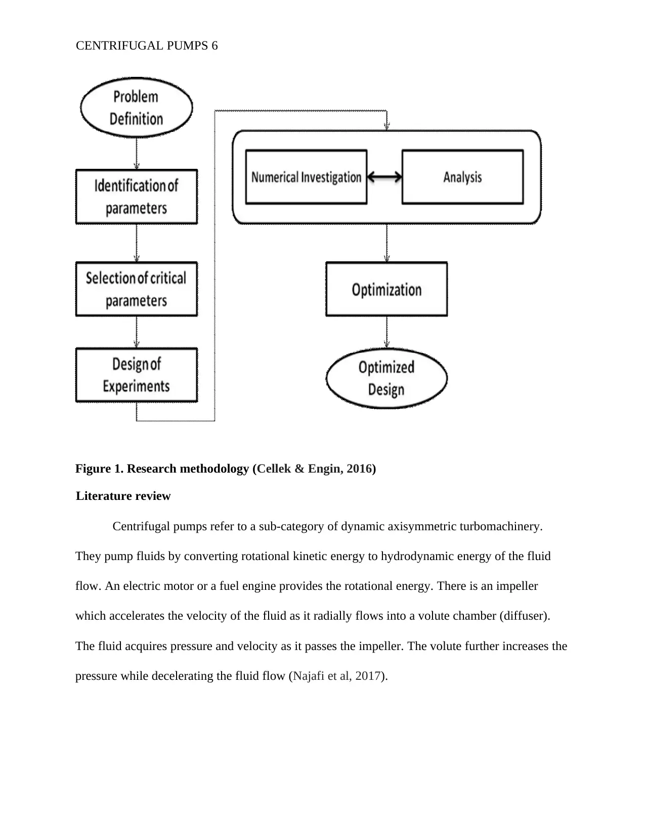
Figure 1. Research methodology (Cellek & Engin, 2016)
Literature review
Centrifugal pumps refer to a sub-category of dynamic axisymmetric turbomachinery.
They pump fluids by converting rotational kinetic energy to hydrodynamic energy of the fluid
flow. An electric motor or a fuel engine provides the rotational energy. There is an impeller
which accelerates the velocity of the fluid as it radially flows into a volute chamber (diffuser).
The fluid acquires pressure and velocity as it passes the impeller. The volute further increases the
pressure while decelerating the fluid flow (Najafi et al, 2017).
CENTRIFUGAL PUMPS 6
⊘ This is a preview!⊘
Do you want full access?
Subscribe today to unlock all pages.
Trusted by 1+ million students worldwide
Experimental and numerical analysis on the modifications of the geometry of the volute
and impeller in centrifugal pumps have been done by several scholars as well as the investigation
of blade outlet angle effect and effect of the width of passage on the centrifugal pump
performance. Performance tests and numerical simulations were conducted to centrifugal pumps
model. In addition, the simulations were used to study ultra-low specific-speed centrifugal pump
and to analyze their hydraulic properties. Using appropriate computational fluid dynamics code
to numerically simulate unsteady flow, the estimation of the total radial loads for the centrifugal
pump’s impeller, under different conditions was done. Similarly, a numerical simulation aids in
the modeling of the characteristics of blade number effect and turbulence (Rezaienia et al, 2017).
Analyses of the unsteady flow in the near-tongue region of the volute-type centrifugal pump at
various operating points were numerically discussed.
A literature survey and industrial experience gave suggestions of critical parameters in the
process of design and whose likelihood of having an impact on the discharge, head, and variation
of power in the pump is high. A parametric study is significant in reducing the number of
analyses needed at each flow rate under investigation by use of a DoE. CFD and the DoE offers a
guideline for the results post-analysis and gives room for variation of performance in tandem
with the design variables adjustment(Zhu et al, 2015). The chief objective of this research is to
foster the growth and development of pump design that will gain ultimate best efficiency, less of
a significant performance loss. Thus, this paper applies the analyses to offer a parametric study
of a wider scope that considers various geometrical features and examines their effect on the
centrifugal pump (van der Schoot &Visser, 2015).
Formulation of the problem
CENTRIFUGAL PUMPS 7
Paraphrase This Document
Need a fresh take? Get an instant paraphrase of this document with our AI Paraphraser
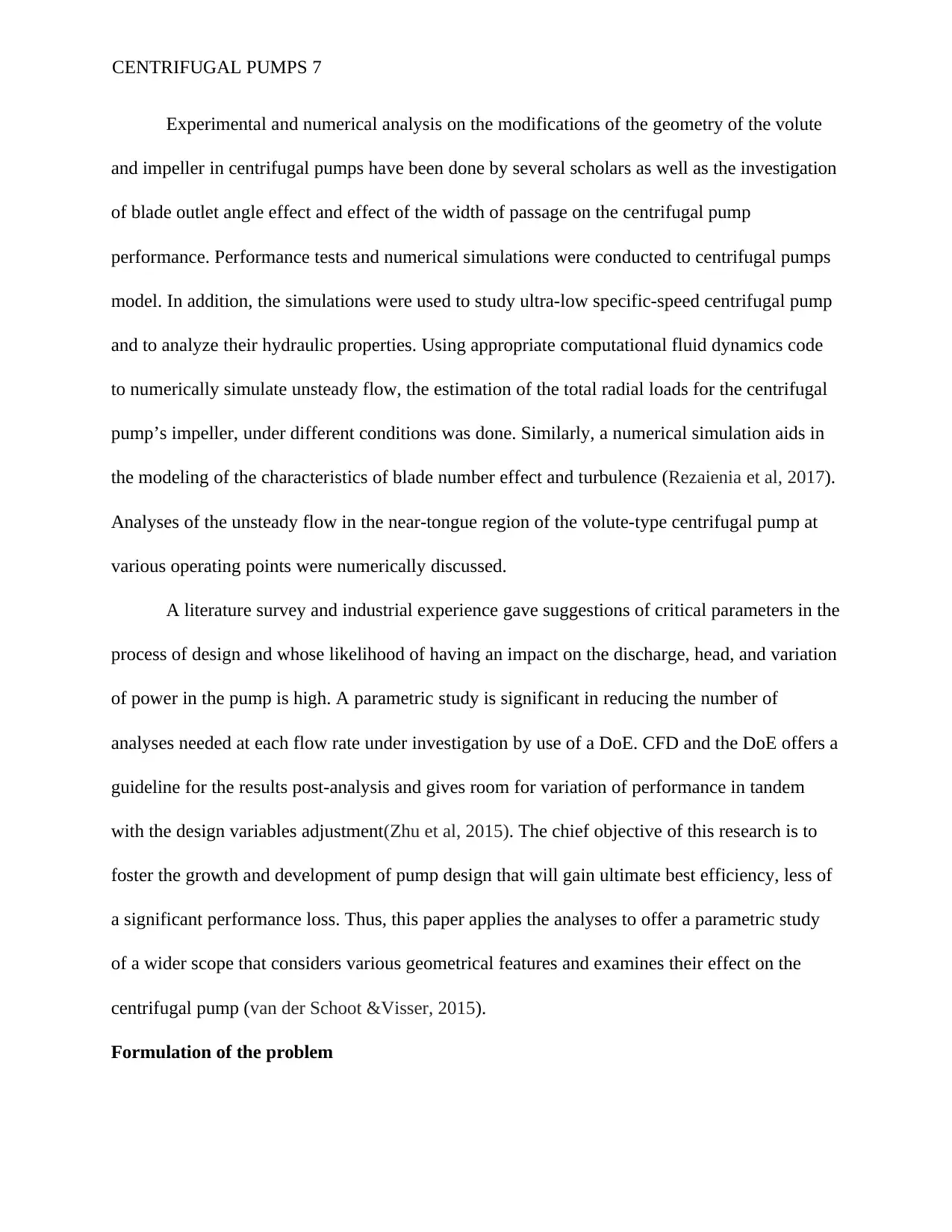
Pump geometry
The pump to be investigated is the type of a low specific-speed home centrifugal water
pump. Figure 2 below shows the pump that will be simulated. It is a volute-type centrifugal
pump, having a singe entry and a specific speed of about 5.87. Its impeller diameter is 16.2cm,
splitter blades and 5 backward-curved blades. The outlet and the inlet angles of the impeller
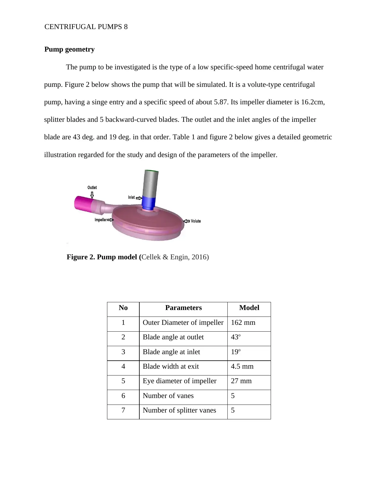
blade are 43 deg. and 19 deg. in that order. Table 1 and figure 2 below gives a detailed geometric
illustration regarded for the study and design of the parameters of the impeller.
Figure 2. Pump model (Cellek & Engin, 2016)
CENTRIFUGAL PUMPS 8
No Parameters Model
1 Outer Diameter of impeller 162 mm
2 Blade angle at outlet 43o
3 Blade angle at inlet 19o
4 Blade width at exit 4.5 mm
5 Eye diameter of impeller 27 mm
6 Number of vanes 5
7 Number of splitter vanes 5
The pump to be investigated is the type of a low specific-speed home centrifugal water
pump. Figure 2 below shows the pump that will be simulated. It is a volute-type centrifugal
pump, having a singe entry and a specific speed of about 5.87. Its impeller diameter is 16.2cm,
splitter blades and 5 backward-curved blades. The outlet and the inlet angles of the impeller
blade are 43 deg. and 19 deg. in that order. Table 1 and figure 2 below gives a detailed geometric
illustration regarded for the study and design of the parameters of the impeller.
Figure 2. Pump model (Cellek & Engin, 2016)
CENTRIFUGAL PUMPS 8
No Parameters Model
1 Outer Diameter of impeller 162 mm
2 Blade angle at outlet 43o
3 Blade angle at inlet 19o
4 Blade width at exit 4.5 mm
5 Eye diameter of impeller 27 mm
6 Number of vanes 5
7 Number of splitter vanes 5
Table 1. Primary design parameters of the impeller (Bellary et al, 2016)
Numerical simulation method
Firstly, the Navier-Stokes equations are solved, including the impeller’s centrifugal force
using the computational fluid dynamics software (AmitKumar et al, 2017).
1. Equations
Here, the 2-D Navier-Stokes, a conservative form of the equations are used for a constant
viscosity fluid’s incompressible flow (Xie et al, 2015).
2. Computation domain and domain discretization
The numerical simulation of the centrifugal pump entails the spatial discretization of flow
domain. Inlet, impeller and the outlet are the three sub-domains of the computational domain
(Guleren, 2018). There are two reference frames, the fixed reference frame, and the rotating
reference frame. The rotating reference frame carries the impeller, while the fixed reference
frame carries the inlet and the outlet. The fixed and the rotating reference frames are connected
to one another by an interface known as the frozen rotor interface (Pei et al, 2017). The frozen
rotor interface uses an algorithm of quasi-static type, in which there is the positioning of the rotor
and stator at fixed/frozen points relative to one another. Separate generation of the computational
domain meshes that comprises of the three sub-domains, outlet, impeller and the inlet (Yu et al,
2016).
Computational fluid dynamics (CFD) analysis
Tools of computational fluid dynamics are applied in the prediction of the performance of
pump under different conditions. The CFD tools help to obtain at any point, various flow
CENTRIFUGAL PUMPS 9
⊘ This is a preview!⊘
Do you want full access?
Subscribe today to unlock all pages.
Trusted by 1+ million students worldwide
characteristics such as temperature, volumetric flow, velocity, pressure etc. the overall pattern of
flow together with the velocity distribution in the entire flow volume can be illustrated
graphically to aid in a better comprehension (Valyukhov et al, 2018).
There are so many assumptions involved in the procedure of a CFD for problem-solving.
Such assumptions include types of elements, number of elements, model of turbulence etc.
assumptions being universal. It becomes difficult and time-consuming to make them. Trial and
error method is used to choose the assumptions that best match the results of CFD with those
from the experiments (Derakhshan & Bashiri, 2018). This process is better known as the best
practice of CFD. The assumptions that best match the CFD outcome with results of the
experiment are kept to be used as the standard values and further used in the optimization process
and analysis (Deng et al, 2017). CFD involves the use of numerical methods to evaluate non-
linear differential equations of Navier-Stokes and allies that give a description of fluid flow, for
boundary conditions and design geometries. The outcome is a rich resource of predictions and
optimizations for temperature, velocity, the concentration of chemicals, density for the regions of
flow (Wang et al, 2017).
Grid independence test
Convergence of grid is a term for describing calculations results improvement through the
use of successive smaller cell sizes (Limbach et al, 2016). The finer the mesh the closer the
calculation gets to the correct solution. This is known as grid convergence. The usual technique
of CFD is to commence the procedure with a rough/course mesh and slowly but steadily make it
finer until the observed results changes are smaller than a predefined tolerance (Korakianitis et
CENTRIFUGAL PUMPS 10
Paraphrase This Document
Need a fresh take? Get an instant paraphrase of this document with our AI Paraphraser
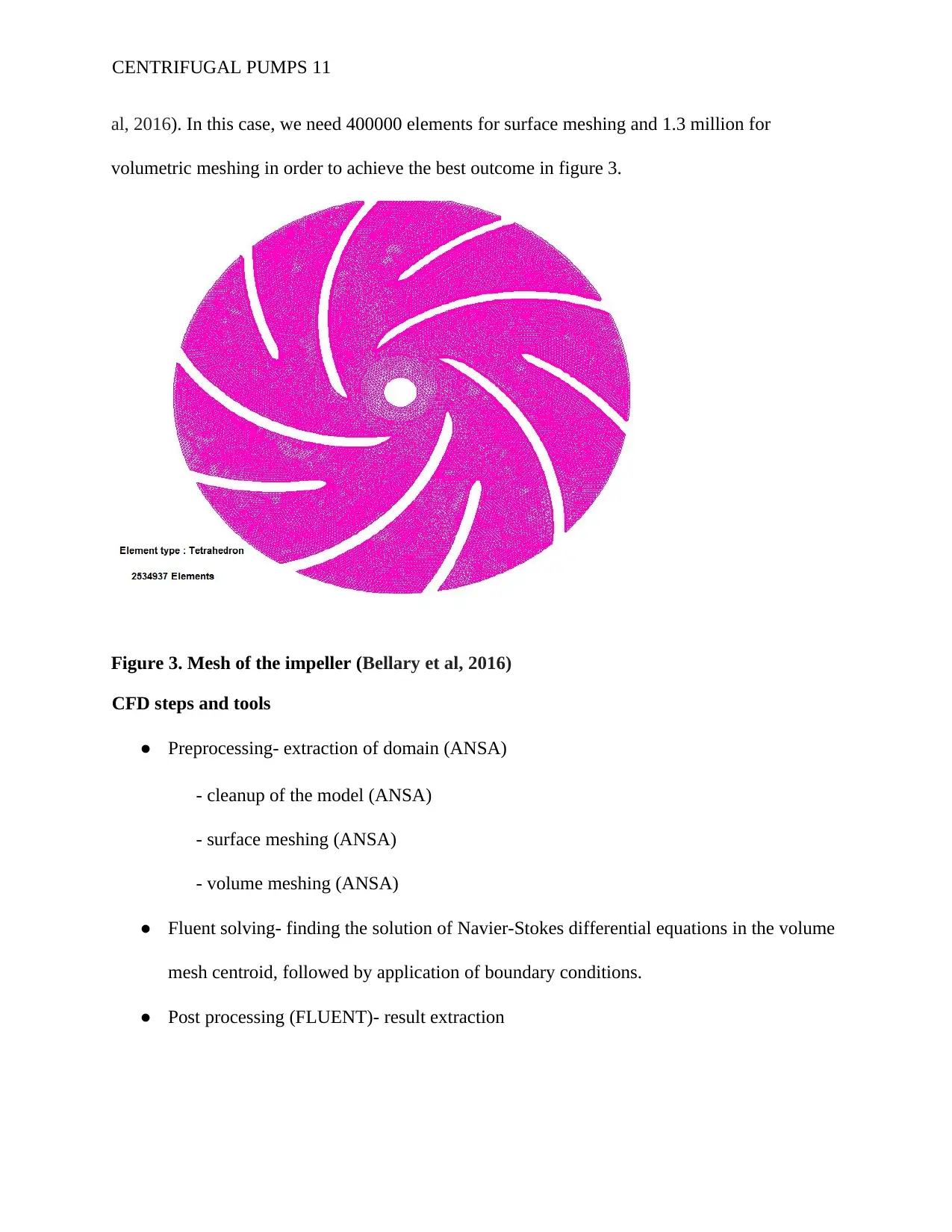
al, 2016). In this case, we need 400000 elements for surface meshing and 1.3 million for
volumetric meshing in order to achieve the best outcome in figure 3.
Figure 3. Mesh of the impeller (Bellary et al, 2016)
CFD steps and tools
● Preprocessing- extraction of domain (ANSA)
- cleanup of the model (ANSA)
- surface meshing (ANSA)
- volume meshing (ANSA)
● Fluent solving- finding the solution of Navier-Stokes differential equations in the volume
mesh centroid, followed by application of boundary conditions.
● Post processing (FLUENT)- result extraction
CENTRIFUGAL PUMPS 11
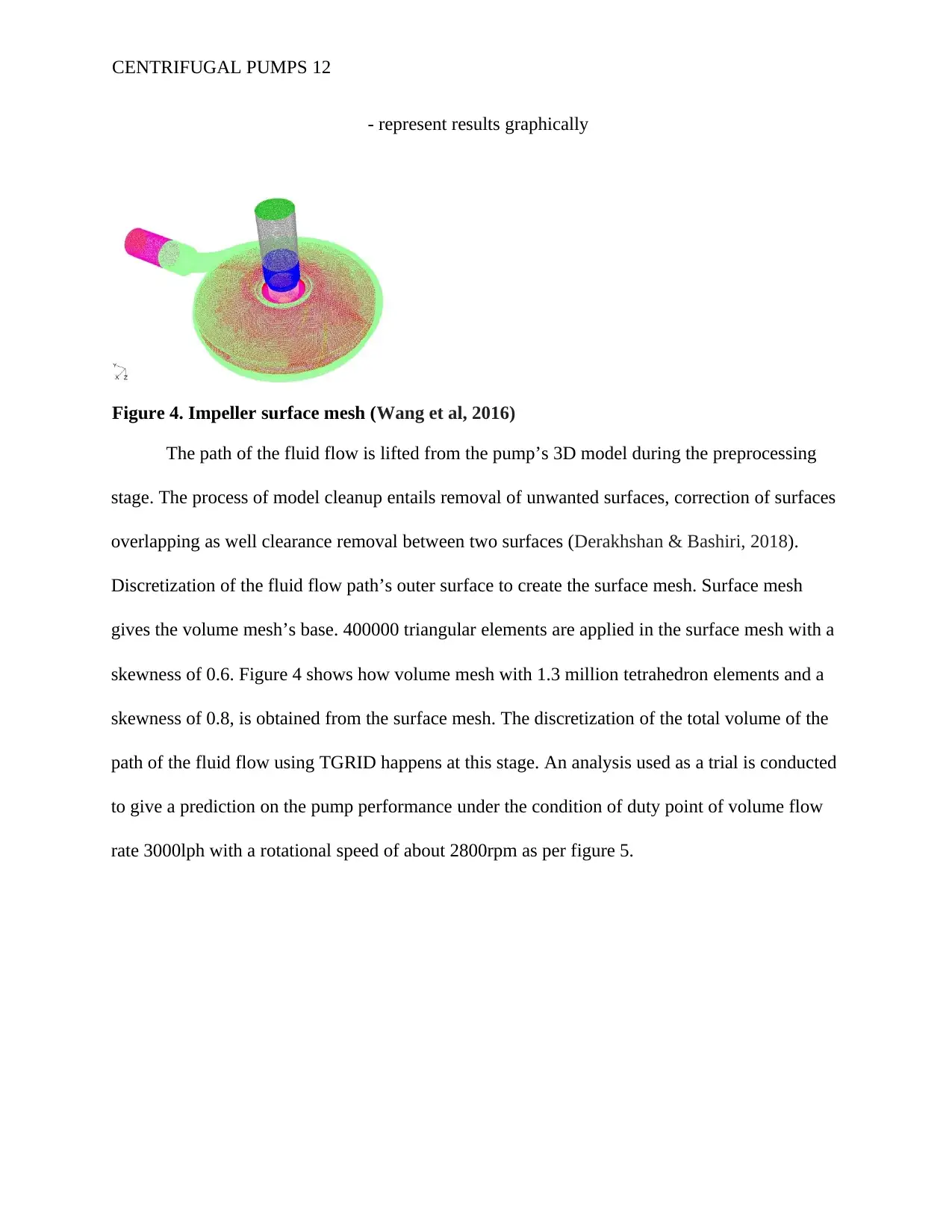
- represent results graphically
Figure 4. Impeller surface mesh (Wang et al, 2016)
The path of the fluid flow is lifted from the pump’s 3D model during the preprocessing
stage. The process of model cleanup entails removal of unwanted surfaces, correction of surfaces
overlapping as well clearance removal between two surfaces (Derakhshan & Bashiri, 2018).
Discretization of the fluid flow path’s outer surface to create the surface mesh. Surface mesh
gives the volume mesh’s base. 400000 triangular elements are applied in the surface mesh with a
skewness of 0.6. Figure 4 shows how volume mesh with 1.3 million tetrahedron elements and a
skewness of 0.8, is obtained from the surface mesh. The discretization of the total volume of the
path of the fluid flow using TGRID happens at this stage. An analysis used as a trial is conducted
to give a prediction on the pump performance under the condition of duty point of volume flow
rate 3000lph with a rotational speed of about 2800rpm as per figure 5.
CENTRIFUGAL PUMPS 12
⊘ This is a preview!⊘
Do you want full access?
Subscribe today to unlock all pages.
Trusted by 1+ million students worldwide
1 out of 24
Related Documents


Your All-in-One AI-Powered Toolkit for Academic Success.
+13062052269
info@desklib.com
Available 24*7 on WhatsApp / Email
![[object Object]](/_next/static/media/star-bottom.7253800d.svg)
Unlock your academic potential
Copyright © 2020–2026 A2Z Services. All Rights Reserved. Developed and managed by ZUCOL.