Project Proposal: Improving CF188 Landing Gear for Safety
VerifiedAdded on 2023/06/13
|22
|4012
|307
Project
AI Summary
This project proposal delves into the study of upgrading the CF188 aircraft's landing gear to mitigate the risk of Planning Mechanism Assembly failure. The primary aim is to research the effectiveness of proposed modifications through a comprehensive analysis involving various methods such as interviews, questionnaires, secondary sources, and experiments. The proposal outlines key objectives, including evaluating static hold-down force during landing gear rigging, confirming bell crank gaps, assessing aircraft ground handling at different speeds, and evaluating loads on planning and connecting links during various landing scenarios. The literature review covers essential aspects of landing gear design, including its purpose, types (fixed and retractable), load considerations, and different arrangements like tail-wheel, tandem, and tricycle-type gears. The methodology section details the approaches to be used for data collection and analysis, emphasizing the importance of understanding the landing gear's role in aircraft safety and performance. This document provides a structured approach to improving the CF188 landing gear system.

PROJECT PROPOSAL 1
PROJECT PROPOSAL
By Name
Course
Instructor
Institution
Location
Date
PROJECT PROPOSAL
By Name
Course
Instructor
Institution
Location
Date
Paraphrase This Document
Need a fresh take? Get an instant paraphrase of this document with our AI Paraphraser

PROJECT PROPOSAL 2
TABLE OF CONTENTS
1.0 Executive summary..............................................................................................................2
2.0 Introduction..........................................................................................................................2
3.0 Thesis statement...................................................................................................................4
4.0 Project Aims and objectives.................................................................................................4
5.0 Definition of key concepts...................................................................................................5
6.0 Literature review..................................................................................................................5
6.1 Purpose of the landing gear........................................................................................5
6.2 Fixed and Retractable Landing Gear..........................................................................5
6.3 Landing gear loads......................................................................................................6
6.4 Landing gear arrangement..........................................................................................7
6.41 Tail Wheel-Type Landing Gear......................................................................7
6.42 Tandem Landing Gear.....................................................................................9
6.43 Tricycle-Type Landing Gear...........................................................................9
6.5 Non-Shock Absorbing and Shock Absorbing Landing Gear...................................10
6.6 Shock Strut................................................................................................................12
7.0 Methodology......................................................................................................................13
7.1 Interviews.................................................................................................................13
7.2 Use of questionnaires................................................................................................13
7.3 Experimentation........................................................................................................13
8.0 Rationale of choice of sample............................................................................................14

PROJECT PROPOSAL 3
9.0 Discussions.........................................................................................................................15
10.0 Conclusion........................................................................................................................16
11.0 References........................................................................................................................18
⊘ This is a preview!⊘
Do you want full access?
Subscribe today to unlock all pages.
Trusted by 1+ million students worldwide
PROJECT PROPOSAL 4
A STUDY OF THE CF188 LANDING GEAR UPGRADE
1.0 Executive summary
The landing gear allows the aircraft to be supported on the ground while it keeps proper
clearance between the ground and the aircraft in order to support the external stores such as
weapons and fuel tank. The main aim of this thesis was to research the effectiveness of the
proposed modifications to the landing gear of the CF188 in order to minimise the risk of
planning Mechanism Assembly failure. The CF 188 aircraft which was under study was
selected due to its landing gear configuration which was providing an opportunity to achieve
all the aims and objectives of the study.
Depending on the requirement of the aircraft, the landing gear may be retractable in order to
reduce the radar cross section or limit the additional drag during the flight. The design of
landing gears is the most challenging part in the design of aircrafts. The landing gear must
have the right size of the shock absorbers and the tires in accordance with the weight of the
aircraft and if it is retractable it must fit into the wheel well without any struggle. The landing
gear must be in the proper location to allow the aircraft to rotate without affecting the tail on
the ground either during landing or take-off. Various methods were used to obtain the data
during the process of the study such as interviews, questionnaires, secondary sources and
experiments.
2.0 Introduction
During the process of aircraft design, the landing gear poses many challenges to the design
team. Depending on the distance, enter of gravity, the angle with the tip- of the tail, the
aircraft weight, shock absorbers and the tires must be of certain specifications and size in
order to allow effective landing and taking off of the aircrafts. In addition, if the landing gear
Paraphrase This Document
Need a fresh take? Get an instant paraphrase of this document with our AI Paraphraser
PROJECT PROPOSAL 5
is designed to retract, therefore it has to be able to fit within the structure which is existing of
the newly designed aircraft. In most cases it is very rare for the structure of the aircraft to be
modified to accommodate the newly designed landing gears (Bakri, 2016, p. 87).
In the case of the F/A -18 the whole landing gear had to be redesigned to sustain the
additional weight from a light fighter aircraft to the medium fighter aircraft (F/A-18) which
had to meet all the navy carrier operations requirements. The increase in the size of the
landing gear resulted to complications of storing within the limited space which was
available in the existing F/A-18.In the nearly designed landing gear during retraction the
shock absorbers required to shrunk and the main wheel required to rotate within a given angle
in order to fit into the wheel well. These special problems during the landing gear retraction
required additional links to the system. The solution which was developed for this problem
was very complex, but the ingenious Planning Mechanism Assembly was developed and it
consisted the bell crank assembly, connecting links, planning arm spring, axle lock and shrink
link (Board, 2014, p. 132).
Although the planning Mechanism Assembly allowed the main landing gear to fit into the
limited space of the wheel well, there were other challenges surfaced. The planning
Mechanism Assembly became one of the weakest parts of the landing gear which resulted to
regular failures. The planning Mechanism Assembly failures usually occurred upon touch
down or shortly thereafter, and in most cases it could occur either on the right or left main
landing gear. Generally, failures of the planning Mechanism Assembly were attributed to the
buckling of the connecting link or the planning link with the signs of the bell crank assembly
contact (Center, 2015, p. 243). In the process of failure the axle lock links became unlocked
resulting to the main wheel deplaning from the main landing path result to loss of direction at
very high speed.

PROJECT PROPOSAL 6
3.0 Thesis statement
This research involved the study of the landing gear of the FC 188 aircraft to come up with
ways through which they can be improved in order to minimise the risk of planning
Mechanism Assembly failure.
Various methods were used to obtain the data during the process of the study such as
interviews, questionnaires, secondary sources and experiments.
4.0 Project Aims and objectives
Aim
The main aim of this thesis was to research the effectiveness of the proposed modifications to
the landing gear of the CF188 in order to minimise the risk of planning Mechanism Assembly
failure.
Objectives
The following objectives were set in order to assist in achieving the main aim of the thesis by
comparing the flight and ground data from the baseline and the prototype main landing gear
configuration of CF188:
o Evaluate static hold down force during the landing gear rigging.
o Confirm the increase of the bell crank gaps and the pin head.
o Evaluate the aircraft grand handling at different ground speeds
o Evaluate the loads on the planning and connecting links during many landings which
include full stop, touch and arresting cable engagement and cable overrun.
⊘ This is a preview!⊘
Do you want full access?
Subscribe today to unlock all pages.
Trusted by 1+ million students worldwide
PROJECT PROPOSAL 7
5.0 Definition of key concepts
The wheel track; this refers to the distance between the main gear and landing tires.
The wheel base; this refers to the distance between the nose landing gear to the main landing
gear (Crist, 2014, p. 53).
Arresting gear; is the mechanical system which is used to decelerate an aircraft rapidly in the
process of landing.
6.0 Literature review
6.1 Purpose of the landing gear
The landing gear is used to allow the aircraft to be controlled during landing, take-off and
other ground operations. Thus the landing gear must have the ability to absorb the stress and
the associated loads. The landing gear allows the aircraft to be to be supported on the ground
while it keeps proper clearance between the ground and the aircraft to support the external
stores such as weapons and fuel tank.
Depending on the requirement of the aircraft, the landing gear may be retractable in order to
reduce the radar cross section or limit the additional drag during the flight (Currey, 2015, p.
456). The landing gear must have the right size of the shock absorbers and the tires in
accordance with the weight of the aircraft and if it is retractable it must fit into the wheel well
without any struggle. The landing gear must be in the proper location to allow the aircraft to
rotate without affecting the tail on the ground either landing or take-off. The landing gear
needs to be very stable and be in a position to provide good steering capabilities which meets
the design requirements.
6.2 Fixed and Retractable Landing Gear
The landing gears can be made into two categories:
Paraphrase This Document
Need a fresh take? Get an instant paraphrase of this document with our AI Paraphraser
PROJECT PROPOSAL 8
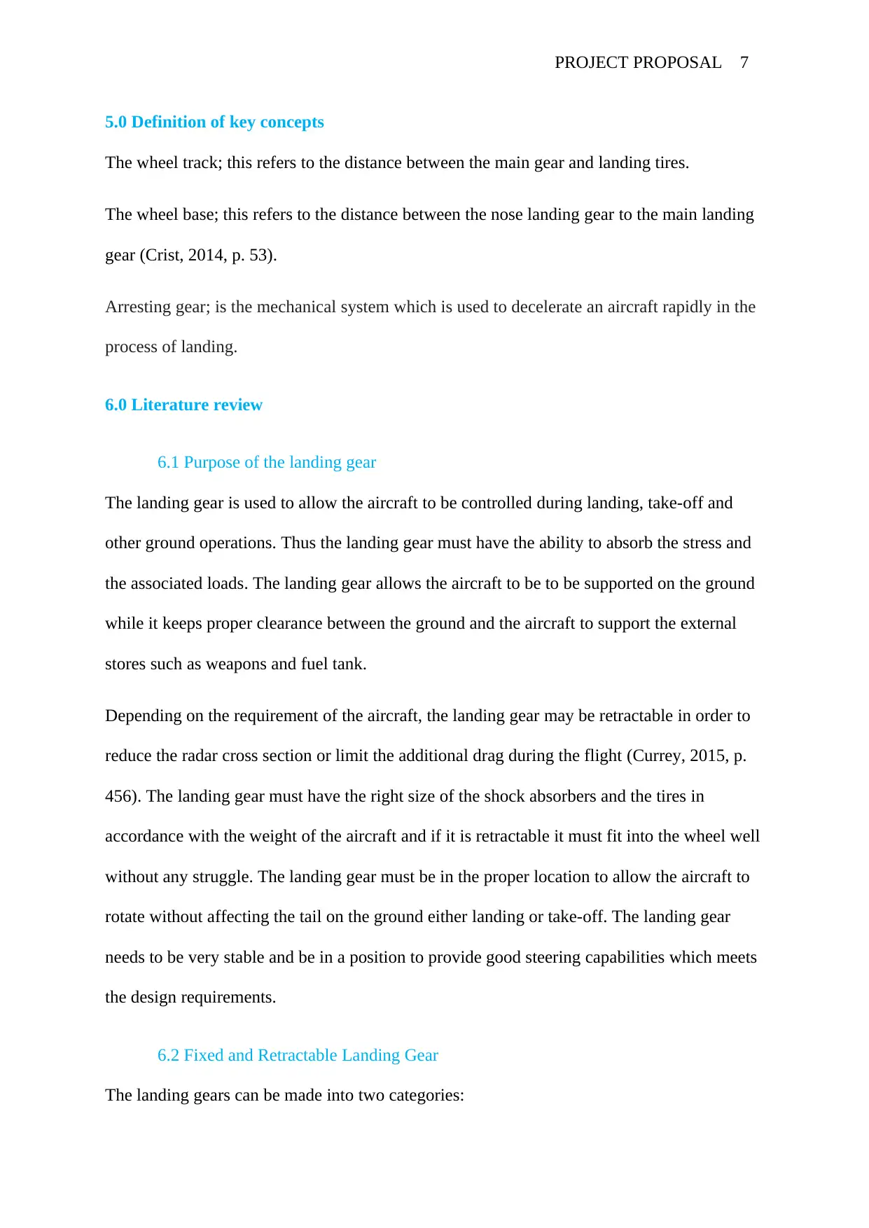
Retractable landing gear
Fixed landing gear
The fixed landing gears means that the landing gears are attached to the airframe and they
always remain exposed to the slipstream during flight (Graham, 2013, p. 876). This type of
landing gears are mainly used in the small single engine aircraft while the Retractable landing
gear stow in wing compartment or fuselage when the aircraft is in flight. As shown in the
figures below.
Fig1: Retractable landing gear fig2: Fixed landing gear
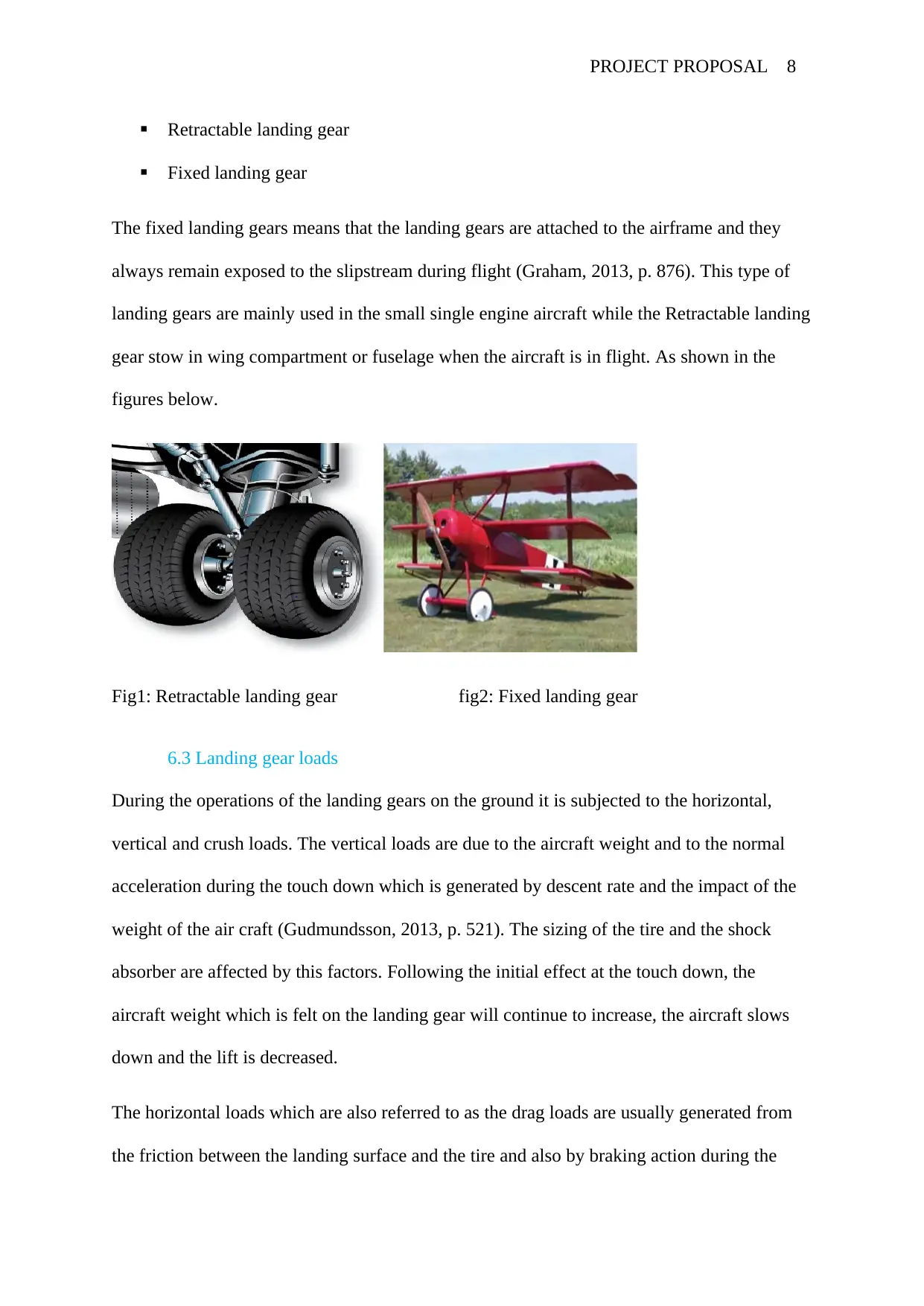
6.3 Landing gear loads
During the operations of the landing gears on the ground it is subjected to the horizontal,
vertical and crush loads. The vertical loads are due to the aircraft weight and to the normal
acceleration during the touch down which is generated by descent rate and the impact of the
weight of the air craft (Gudmundsson, 2013, p. 521). The sizing of the tire and the shock
absorber are affected by this factors. Following the initial effect at the touch down, the
aircraft weight which is felt on the landing gear will continue to increase, the aircraft slows
down and the lift is decreased.
The horizontal loads which are also referred to as the drag loads are usually generated from
the friction between the landing surface and the tire and also by braking action during the
Retractable landing gear
Fixed landing gear
The fixed landing gears means that the landing gears are attached to the airframe and they
always remain exposed to the slipstream during flight (Graham, 2013, p. 876). This type of
landing gears are mainly used in the small single engine aircraft while the Retractable landing
gear stow in wing compartment or fuselage when the aircraft is in flight. As shown in the
figures below.
Fig1: Retractable landing gear fig2: Fixed landing gear
6.3 Landing gear loads
During the operations of the landing gears on the ground it is subjected to the horizontal,
vertical and crush loads. The vertical loads are due to the aircraft weight and to the normal
acceleration during the touch down which is generated by descent rate and the impact of the
weight of the air craft (Gudmundsson, 2013, p. 521). The sizing of the tire and the shock
absorber are affected by this factors. Following the initial effect at the touch down, the
aircraft weight which is felt on the landing gear will continue to increase, the aircraft slows
down and the lift is decreased.
The horizontal loads which are also referred to as the drag loads are usually generated from
the friction between the landing surface and the tire and also by braking action during the
PROJECT PROPOSAL 9
deceleration process (Gudmundsson, 2013, p. 76). This horizontal loads are encountered by a
drag brace. The lateral loads are generated either during the crabbed landing or during the
turns on the ground where any roll leads to lateral force component. The lateral forces are
usually experienced by the side brace (Hailiang, 2014, p. 162).
The crush loads occurs when the aircraft runs over a sharp object for example the arresting
cable.
There are variables which affects these loads and they include:
Weight of the aircraft.
Descent rate
Aircraft attitude (yaw, in roll and the pitch)
Deceleration requirements which are driven by the runway length or the distance
variables which are available post touch down.
Landing gear serving and maintenance.
All the above mentioned factors are affected by wind and density (Lixin, 2017, p. 422).
6.4 Landing gear arrangement.
There three basic arrangements of landing gears:
i. Wheel type landing gear (convectional gear).
ii. Tandem landing gears
iii. Tricycle-type landing gear
6.41 Tail Wheel-Type Landing Gear
Tail wheel-type landing gear which is also referred to as convectional gear because most of
the early aircrafts uses this type of the landing gear arrangement. In this arrangement the
main gear are located at the forward centre of gravity, due to that the tail is forced to have
⊘ This is a preview!⊘
Do you want full access?
Subscribe today to unlock all pages.
Trusted by 1+ million students worldwide
PROJECT PROPOSAL 10
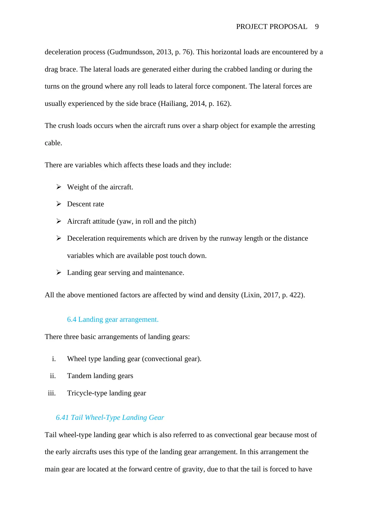
support from the third wheel assembly. This type of arrangement allows the aircraft to slow
down upon landing and at the same time offer directional stability. The resulting angle of
fuselage, when the aircraft is fitted with the wheel-type conventional gear, permits the
application of the long propeller which compensates for older and underpowered
engines .The increased clearance of the forward fuselage which is offered by the tail wheel
type of the landing gears is also very beneficial when operating in and out of the unpaved
runways. In the modern time, the aircrafts are manufactured with this type of landing gears
because of the reasons mentioned above and weight savings accompanying the light tail
wheel-type landing gears (Wolfe, 2014, p. 611). As shown in the figure below.
Fig 3: Tail wheel configuration landing gear on a DC-3
Paraphrase This Document
Need a fresh take? Get an instant paraphrase of this document with our AI Paraphraser
PROJECT PROPOSAL 11
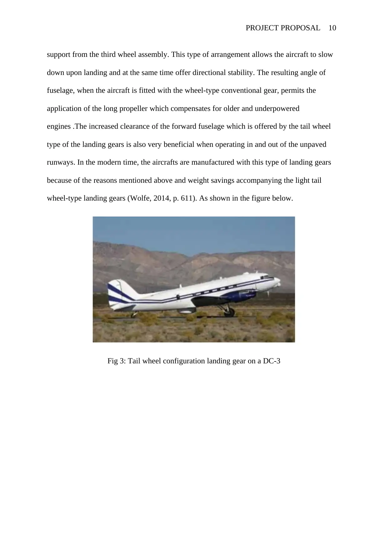
Fig 4: The steerable tail wheel of a Pitts Special
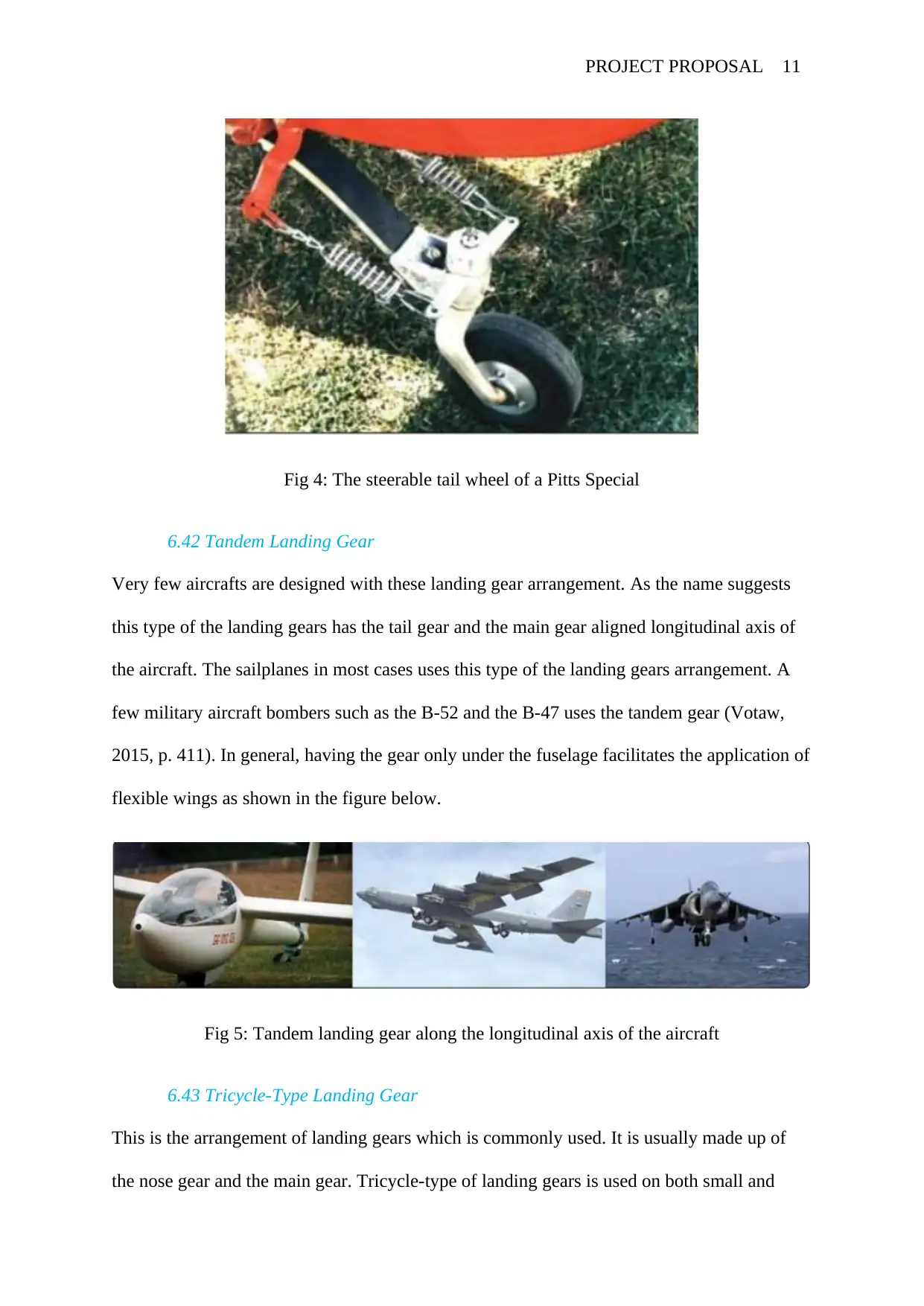
6.42 Tandem Landing Gear
Very few aircrafts are designed with these landing gear arrangement. As the name suggests
this type of the landing gears has the tail gear and the main gear aligned longitudinal axis of
the aircraft. The sailplanes in most cases uses this type of the landing gears arrangement. A
few military aircraft bombers such as the B-52 and the B-47 uses the tandem gear (Votaw,
2015, p. 411). In general, having the gear only under the fuselage facilitates the application of
flexible wings as shown in the figure below.
Fig 5: Tandem landing gear along the longitudinal axis of the aircraft
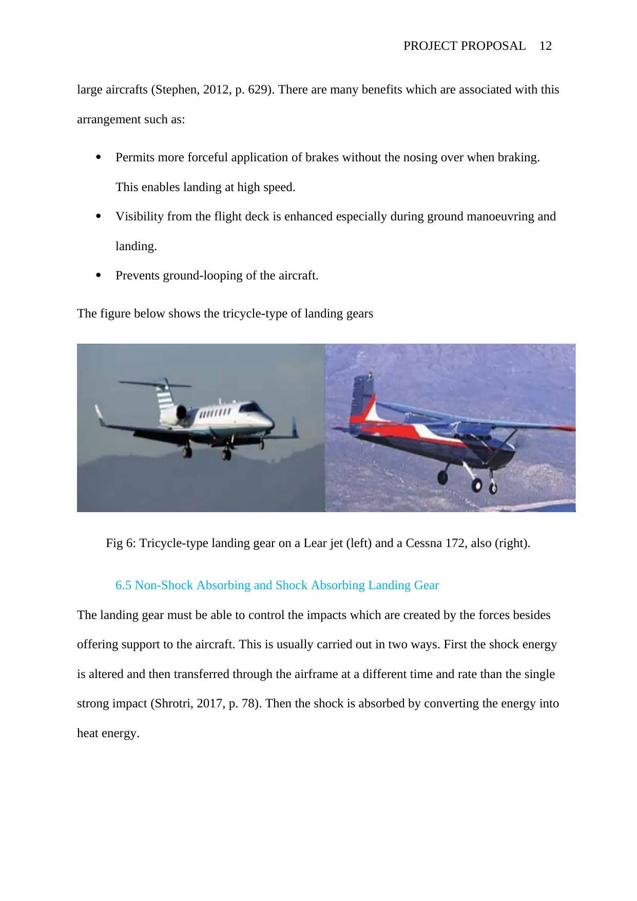
6.43 Tricycle-Type Landing Gear
This is the arrangement of landing gears which is commonly used. It is usually made up of
the nose gear and the main gear. Tricycle-type of landing gears is used on both small and
Fig 4: The steerable tail wheel of a Pitts Special
6.42 Tandem Landing Gear
Very few aircrafts are designed with these landing gear arrangement. As the name suggests
this type of the landing gears has the tail gear and the main gear aligned longitudinal axis of
the aircraft. The sailplanes in most cases uses this type of the landing gears arrangement. A
few military aircraft bombers such as the B-52 and the B-47 uses the tandem gear (Votaw,
2015, p. 411). In general, having the gear only under the fuselage facilitates the application of
flexible wings as shown in the figure below.
Fig 5: Tandem landing gear along the longitudinal axis of the aircraft
6.43 Tricycle-Type Landing Gear
This is the arrangement of landing gears which is commonly used. It is usually made up of
the nose gear and the main gear. Tricycle-type of landing gears is used on both small and
PROJECT PROPOSAL 12
large aircrafts (Stephen, 2012, p. 629). There are many benefits which are associated with this
arrangement such as:
Permits more forceful application of brakes without the nosing over when braking.
This enables landing at high speed.
Visibility from the flight deck is enhanced especially during ground manoeuvring and
landing.
Prevents ground-looping of the aircraft.
The figure below shows the tricycle-type of landing gears
Fig 6: Tricycle-type landing gear on a Lear jet (left) and a Cessna 172, also (right).
6.5 Non-Shock Absorbing and Shock Absorbing Landing Gear
The landing gear must be able to control the impacts which are created by the forces besides
offering support to the aircraft. This is usually carried out in two ways. First the shock energy
is altered and then transferred through the airframe at a different time and rate than the single
strong impact (Shrotri, 2017, p. 78). Then the shock is absorbed by converting the energy into
heat energy.
⊘ This is a preview!⊘
Do you want full access?
Subscribe today to unlock all pages.
Trusted by 1+ million students worldwide
1 out of 22


Your All-in-One AI-Powered Toolkit for Academic Success.
+13062052269
info@desklib.com
Available 24*7 on WhatsApp / Email
![[object Object]](/_next/static/media/star-bottom.7253800d.svg)
Unlock your academic potential
Copyright © 2020–2026 A2Z Services. All Rights Reserved. Developed and managed by ZUCOL.