CFD Analysis of a Commercial Vehicle: Aerodynamic Modifications
VerifiedAdded on 2022/09/01
|15
|3443
|26
Report
AI Summary
This report presents a CFD analysis of a commercial vehicle, specifically focusing on the aerodynamic characteristics of a truck. The study investigates the application of CFD simulation to determine drag and lift forces, crucial factors influencing fuel efficiency and vehicle performance. The report delves into various aerodynamic modifications implemented on trucks to reduce these forces, including profile edge chamfering, windscreen rake adjustments, and the use of front skirts, side skirts, and diffusers. The methodology involves creating a 3D model of the truck, setting up the simulation in ANSYS CFX, applying appropriate boundary conditions, and meshing the geometry. The results section compares the original and modified truck models, analyzing surface plots and streamlines to visualize airflow patterns and quantify the impact of the aerodynamic modifications. The report concludes with recommendations for further improvements and emphasizes the importance of CFD in optimizing truck designs for better aerodynamic efficiency. The document is contributed by a student to be published on the website Desklib. Desklib is a platform which provides all the necessary AI based study tools for students.
CFX ON TRUCK
Contents
ABSTRACT ................................................................................................................................................ 3
INTRODUCTION ....................................................................................................................................... 3
Boundary layer. ................................................................................................................................... 3
Skin Friction. ........................................................................................................................................ 4
Air airstream. ...................................................................................................................................... 4
Aerodynamic drag. .............................................................................................................................. 4
Aerodynamic lift. ................................................................................................................................. 4
Vehicle lift. .......................................................................................................................................... 5
VARIOUS AERODYNAMIC MODIFICATIONS ON TRUCK .......................................................................... 5
Profile edge chamfering and filleting. ................................................................................................. 5
Windscreen rake. ................................................................................................................................ 5
Front bumper ...................................................................................................................................... 5
Front skirt. ........................................................................................................................................... 5
Side skirts ............................................................................................................................................ 5
Flat underbody. ................................................................................................................................... 5
Diffuser. ............................................................................................................................................... 5
Cab deflector ....................................................................................................................................... 6
Chassis Fairings ................................................................................................................................... 6
METHODOLOGY ...................................................................................................................................... 7
UNMODIFIED VAN............................................................................................................................... 7
PRE-MODELING. .............................................................................................................................. 7
Geometry ........................................................................................................................................ 7
Mesh ............................................................................................................................................... 7
SETUP .............................................................................................................................................. 8
Solution. ........................................................................................................................................ 11
MODIFICATIONS ................................................................................................................................ 11
RESULTS AND DISCUSSION.................................................................................................................... 13
ORIGINAL MODEL.............................................................................................................................. 13
Surface Plots ................................................................................................................................. 13
Streamlines ................................................................................................................................... 13
Paraphrase This Document
Need a fresh take? Get an instant paraphrase of this document with our AI Paraphraser
MODIFIED TRUCK .............................................................................................................................. 14
Surface plots ................................................................................................................................. 14
COMPARISSON BETWEEN ORIGINAL MODEL AND MODIFIED MODEL ............................................ 14
CONCLUSION ......................................................................................................................................... 15
RECOMMENDATION ............................................................................................................................. 15
REFERENCES .......................................................................................................................................... 15
ABSTRACT
This task aims at showcasing the use of CFD simulation in determining the drag and lift forces of a
truck. There are various elements or modifications which are made on the bodies of trucks to reduce
the drag and lift forces. The effect of putting various aerodynamic elements to the body of a truck is
also illustrated.
INTRODUCTION
Solid body aerodynamics is the study of flow of air around a solid model comparing it with the
surrounding air with its speed. A truck aerodynamics or any other car in this case is also considered
as solid body aerodynamics since it involves study of air around a model. There are several forces
offering resistance to the flow of air acting around a model moving in air. The common forces are
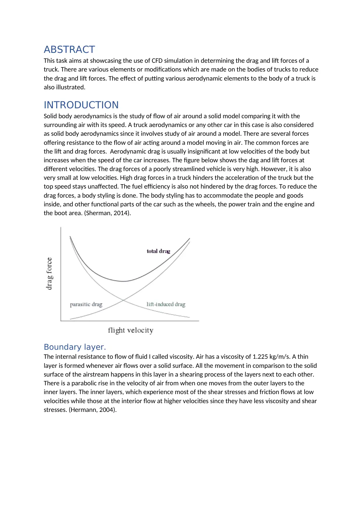
the lift and drag forces. Aerodynamic drag is usually insignificant at low velocities of the body but
increases when the speed of the car increases. The figure below shows the dag and lift forces at
different velocities. The drag forces of a poorly streamlined vehicle is very high. However, it is also
very small at low velocities. High drag forces in a truck hinders the acceleration of the truck but the
top speed stays unaffected. The fuel efficiency is also not hindered by the drag forces. To reduce the
drag forces, a body styling is done. The body styling has to accommodate the people and goods
inside, and other functional parts of the car such as the wheels, the power train and the engine and
the boot area. (Sherman, 2014).
Boundary layer.
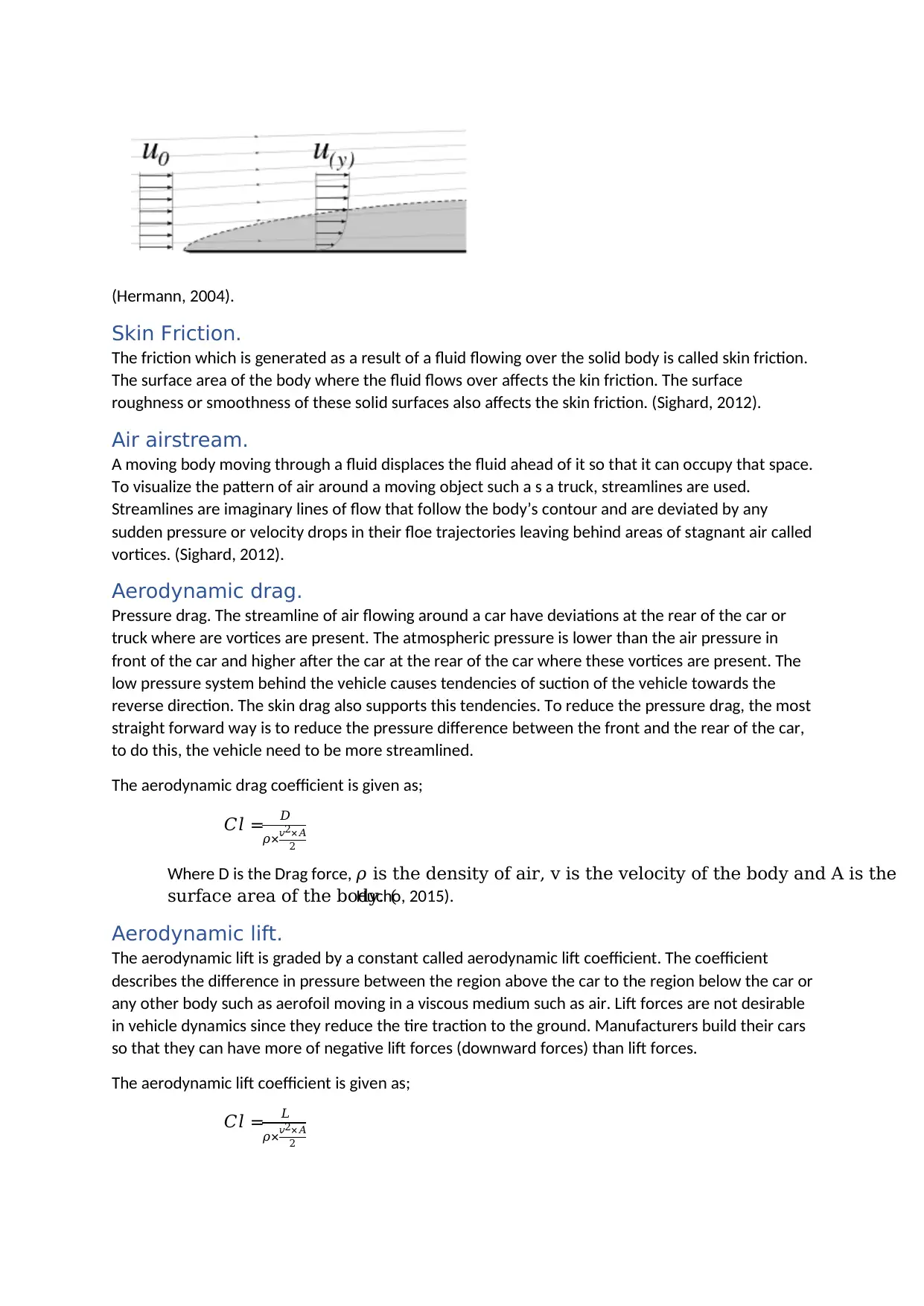
The internal resistance to flow of fluid I called viscosity. Air has a viscosity of 1.225 kg/m/s. A thin
layer is formed whenever air flows over a solid surface. All the movement in comparison to the solid
surface of the airstream happens in this layer in a shearing process of the layers next to each other.
There is a parabolic rise in the velocity of air from when one moves from the outer layers to the
inner layers. The inner layers, which experience most of the shear stresses and friction flows at low
velocities while those at the interior flow at higher velocities since they have less viscosity and shear
stresses. (Hermann, 2004).
This task aims at showcasing the use of CFD simulation in determining the drag and lift forces of a
truck. There are various elements or modifications which are made on the bodies of trucks to reduce
the drag and lift forces. The effect of putting various aerodynamic elements to the body of a truck is
also illustrated.
INTRODUCTION
Solid body aerodynamics is the study of flow of air around a solid model comparing it with the
surrounding air with its speed. A truck aerodynamics or any other car in this case is also considered
as solid body aerodynamics since it involves study of air around a model. There are several forces
offering resistance to the flow of air acting around a model moving in air. The common forces are
the lift and drag forces. Aerodynamic drag is usually insignificant at low velocities of the body but
increases when the speed of the car increases. The figure below shows the dag and lift forces at
different velocities. The drag forces of a poorly streamlined vehicle is very high. However, it is also
very small at low velocities. High drag forces in a truck hinders the acceleration of the truck but the
top speed stays unaffected. The fuel efficiency is also not hindered by the drag forces. To reduce the
drag forces, a body styling is done. The body styling has to accommodate the people and goods
inside, and other functional parts of the car such as the wheels, the power train and the engine and
the boot area. (Sherman, 2014).
Boundary layer.
The internal resistance to flow of fluid I called viscosity. Air has a viscosity of 1.225 kg/m/s. A thin
layer is formed whenever air flows over a solid surface. All the movement in comparison to the solid
surface of the airstream happens in this layer in a shearing process of the layers next to each other.
There is a parabolic rise in the velocity of air from when one moves from the outer layers to the
inner layers. The inner layers, which experience most of the shear stresses and friction flows at low
velocities while those at the interior flow at higher velocities since they have less viscosity and shear
stresses. (Hermann, 2004).
⊘ This is a preview!⊘
Do you want full access?
Subscribe today to unlock all pages.
Trusted by 1+ million students worldwide
(Hermann, 2004).
Skin Friction.
The friction which is generated as a result of a fluid flowing over the solid body is called skin friction.
The surface area of the body where the fluid flows over affects the kin friction. The surface
roughness or smoothness of these solid surfaces also affects the skin friction. (Sighard, 2012).
Air airstream.
A moving body moving through a fluid displaces the fluid ahead of it so that it can occupy that space.
To visualize the pattern of air around a moving object such a s a truck, streamlines are used.
Streamlines are imaginary lines of flow that follow the body’s contour and are deviated by any
sudden pressure or velocity drops in their floe trajectories leaving behind areas of stagnant air called
vortices. (Sighard, 2012).
Aerodynamic drag.
Pressure drag. The streamline of air flowing around a car have deviations at the rear of the car or
truck where are vortices are present. The atmospheric pressure is lower than the air pressure in
front of the car and higher after the car at the rear of the car where these vortices are present. The
low pressure system behind the vehicle causes tendencies of suction of the vehicle towards the
reverse direction. The skin drag also supports this tendencies. To reduce the pressure drag, the most
straight forward way is to reduce the pressure difference between the front and the rear of the car,
to do this, the vehicle need to be more streamlined.
The aerodynamic drag coefficient is given as;
𝐶𝑙 = 𝐷
𝜌×𝑣2×𝐴
2
Where D is the Drag force, 𝜌 is the density of air, v is the velocity of the body and A is the
surface area of the body. (Hucho, 2015).
Aerodynamic lift.
The aerodynamic lift is graded by a constant called aerodynamic lift coefficient. The coefficient
describes the difference in pressure between the region above the car to the region below the car or
any other body such as aerofoil moving in a viscous medium such as air. Lift forces are not desirable
in vehicle dynamics since they reduce the tire traction to the ground. Manufacturers build their cars
so that they can have more of negative lift forces (downward forces) than lift forces.
The aerodynamic lift coefficient is given as;
𝐶𝑙 = 𝐿
𝜌×𝑣2×𝐴
2
Paraphrase This Document
Need a fresh take? Get an instant paraphrase of this document with our AI Paraphraser
Where L is the lift force, 𝜌 is the density of air, v is the velocity of the body and A is the
surface area of the body. The value of A can be determined from the CAD software.
(Hucho, 2015).
Vehicle lift.
Vehicle lift is caused whenever the air flowing above the truck flows at a higher velocity than that
flowing beneath the truck thus causing a lower pressure above the truck. The lift coefficient is mainly
affected by the styling of the truck body under the body and over the body, the velocity of flow and
the distance of clearance of the truck from the ground. (Sighard, 2012).
VARIOUS AERODYNAMIC MODIFICATIONS ON TRUCK
This are done to increase the fuel efficiencies by reducing the fuel consumption. Reducing the lift
forces and the drag forces will help a lot in achieving this goals. It is also a good practice since in the
long run, reducing the fuel consumption helps conserve the environment. There are various ways of
styling a truck for better aerodynamic properties as discussed below.
Profile edge chamfering and filleting.
The drag forces increases with the increase in the sharpness of the corners of the vehicle. Breaking
the sharpness of some of the areas in the models by chamfering and filleting helps in reducing the
lift and drag coefficients. However, studies have shown that reducing further from 40 mm of radius
offers little advantage since there is an insignificant reduction in the drag and lift coefficients.
Windscreen rake.
For vehicles with a bonnet, the slope of the bonne can be reduced so as to reduce the drag. For
instance, reducing the rake angle by 10 degrees reduces the drag coefficient with a significant
amount but beyond 10 degrees, the reduction in drag becomes insignificant. Also reducing the rake
angle of the wind screen by 10 degrees reduces the drag force and drag coefficient but beyond this,
the screen may interfere with space of the cabin. (Seabaugh, 2016).
Front bumper
The front bumper I an aerodynamic element which controls how the air flows over the wheels. They
tend to direct air to flow away from the wheels where there are more vortices.
Front skirt.
The front skirt is important in that instead of letting the displaced air to flow all around the truck, it
passes through the front of the lorry where some is used to cool the heated components of the
engine and also to pass through the radiator.
Side skirts
The side skirts allows prevents the air flowing beneath the van or truck to redistribute forming
vortices hence reducing the drag forces. (Frank, 2013).
Flat underbody.
The underbody of the vehicle can be made flat so as to reduce the air resistance below the vehicle.
For vans and other small cars, this is achievable but for trucks, a flat underbody is not achievable.
Diffuser.
This is one of the most important aerodynamics elements for vehicles. Parameters of the diffuser
include the diffuser angle and the stages and the number of separators for the diffuser. The diffuser
in most cases reduce the lift forces. However for sport vehicles, it can be used for both drag
reduction and lift force reduction. For instance, while cornering, the diffuser increases the drag
forces and the lift forces to slow down the car while pressing the car to the ground harder to cause
more road traction thus enabling easier maneuvering of the car. (Lambert, 2015).
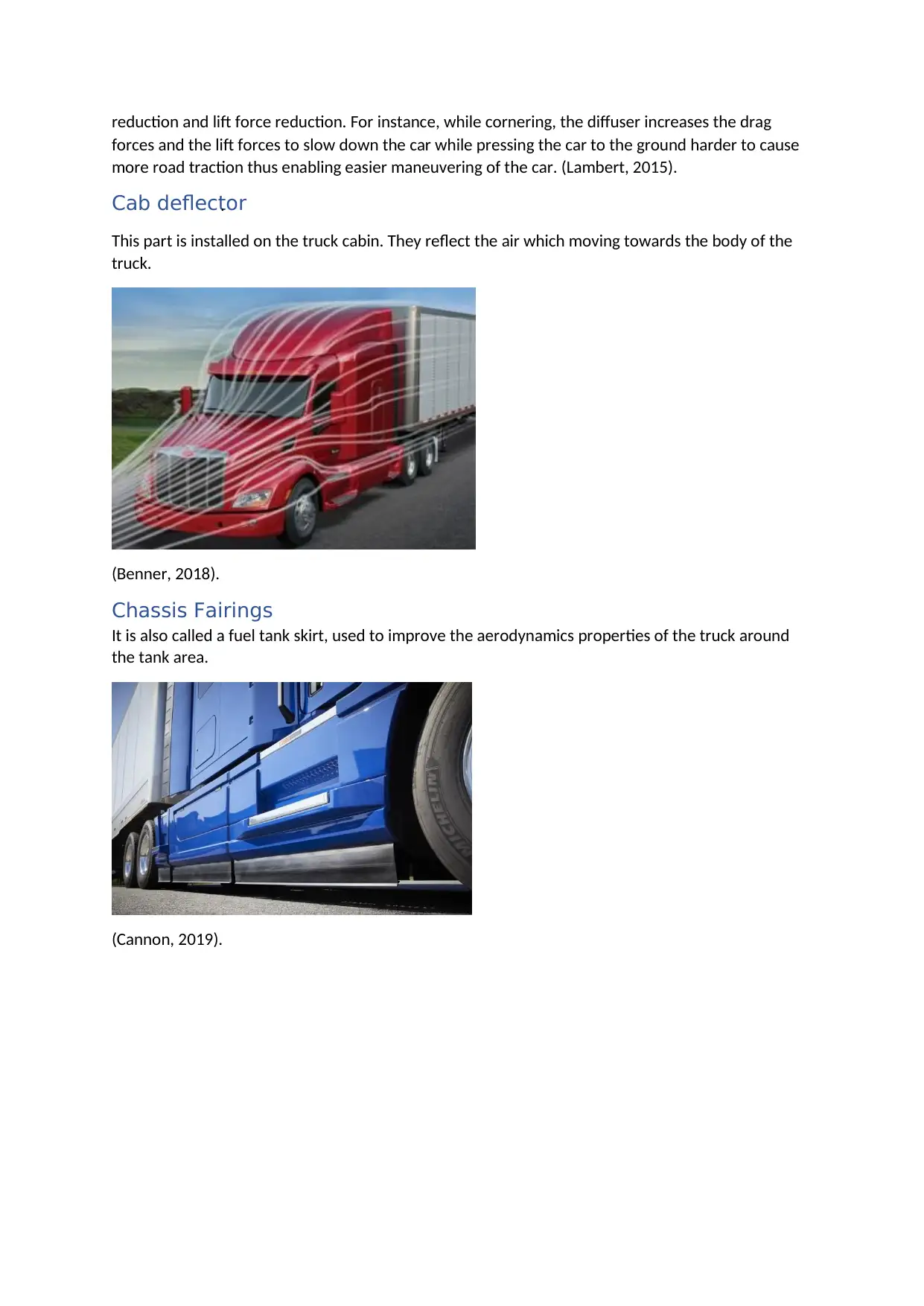
Cab deflector.
This part is installed on the truck cabin. They reflect the air which moving towards the body of the
truck.
(Benner, 2018).
Chassis Fairings
It is also called a fuel tank skirt, used to improve the aerodynamics properties of the truck around
the tank area.
(Cannon, 2019).
forces and the lift forces to slow down the car while pressing the car to the ground harder to cause
more road traction thus enabling easier maneuvering of the car. (Lambert, 2015).
Cab deflector.
This part is installed on the truck cabin. They reflect the air which moving towards the body of the
truck.
(Benner, 2018).
Chassis Fairings
It is also called a fuel tank skirt, used to improve the aerodynamics properties of the truck around
the tank area.
(Cannon, 2019).
⊘ This is a preview!⊘
Do you want full access?
Subscribe today to unlock all pages.
Trusted by 1+ million students worldwide
METHODOLOGY
UNMODIFIED VAN
PRE-MODELING.
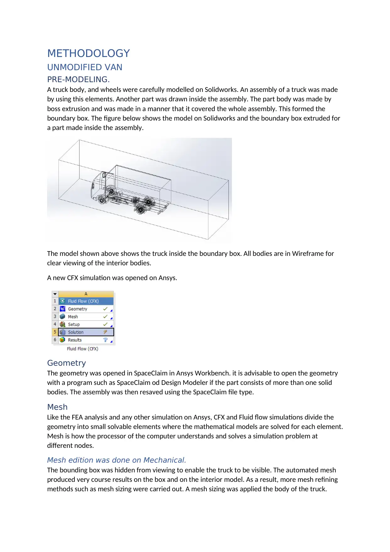
A truck body, and wheels were carefully modelled on Solidworks. An assembly of a truck was made
by using this elements. Another part was drawn inside the assembly. The part body was made by
boss extrusion and was made in a manner that it covered the whole assembly. This formed the
boundary box. The figure below shows the model on Solidworks and the boundary box extruded for
a part made inside the assembly.
The model shown above shows the truck inside the boundary box. All bodies are in Wireframe for
clear viewing of the interior bodies.
A new CFX simulation was opened on Ansys.
Geometry
The geometry was opened in SpaceClaim in Ansys Workbench. it is advisable to open the geometry
with a program such as SpaceClaim od Design Modeler if the part consists of more than one solid
bodies. The assembly was then resaved using the SpaceClaim file type.
Mesh
Like the FEA analysis and any other simulation on Ansys, CFX and Fluid flow simulations divide the
geometry into small solvable elements where the mathematical models are solved for each element.
Mesh is how the processor of the computer understands and solves a simulation problem at
different nodes.
Mesh edition was done on Mechanical.
The bounding box was hidden from viewing to enable the truck to be visible. The automated mesh
produced very course results on the box and on the interior model. As a result, more mesh refining
methods such as mesh sizing were carried out. A mesh sizing was applied the body of the truck.
UNMODIFIED VAN
PRE-MODELING.
A truck body, and wheels were carefully modelled on Solidworks. An assembly of a truck was made
by using this elements. Another part was drawn inside the assembly. The part body was made by
boss extrusion and was made in a manner that it covered the whole assembly. This formed the
boundary box. The figure below shows the model on Solidworks and the boundary box extruded for
a part made inside the assembly.
The model shown above shows the truck inside the boundary box. All bodies are in Wireframe for
clear viewing of the interior bodies.
A new CFX simulation was opened on Ansys.
Geometry
The geometry was opened in SpaceClaim in Ansys Workbench. it is advisable to open the geometry
with a program such as SpaceClaim od Design Modeler if the part consists of more than one solid
bodies. The assembly was then resaved using the SpaceClaim file type.
Mesh
Like the FEA analysis and any other simulation on Ansys, CFX and Fluid flow simulations divide the
geometry into small solvable elements where the mathematical models are solved for each element.
Mesh is how the processor of the computer understands and solves a simulation problem at
different nodes.
Mesh edition was done on Mechanical.
The bounding box was hidden from viewing to enable the truck to be visible. The automated mesh
produced very course results on the box and on the interior model. As a result, more mesh refining
methods such as mesh sizing were carried out. A mesh sizing was applied the body of the truck.
Paraphrase This Document
Need a fresh take? Get an instant paraphrase of this document with our AI Paraphraser
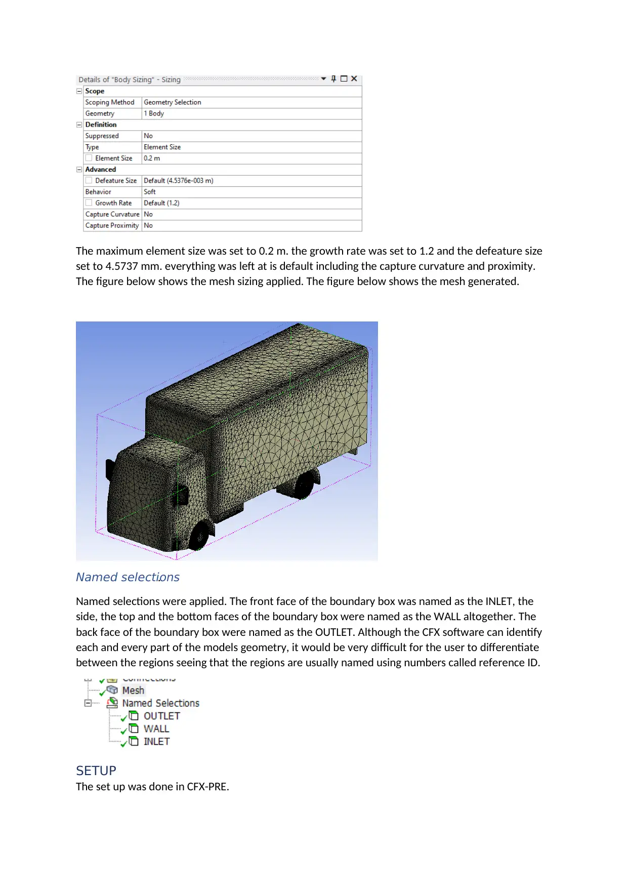
The maximum element size was set to 0.2 m. the growth rate was set to 1.2 and the defeature size
set to 4.5737 mm. everything was left at is default including the capture curvature and proximity.
The figure below shows the mesh sizing applied. The figure below shows the mesh generated.
Named selections.
Named selections were applied. The front face of the boundary box was named as the INLET, the
side, the top and the bottom faces of the boundary box were named as the WALL altogether. The
back face of the boundary box were named as the OUTLET. Although the CFX software can identify
each and every part of the models geometry, it would be very difficult for the user to differentiate
between the regions seeing that the regions are usually named using numbers called reference ID.
SETUP
The set up was done in CFX-PRE.
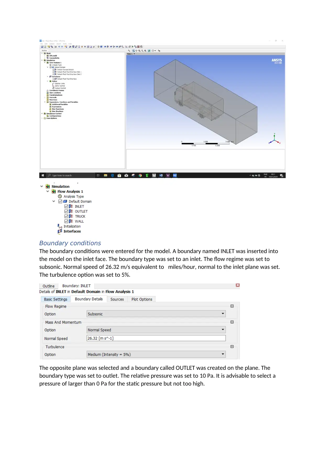
Boundary conditions
The boundary conditions were entered for the model. A boundary named INLET was inserted into
the model on the inlet face. The boundary type was set to an inlet. The flow regime was set to
subsonic. Normal speed of 26.32 m/s equivalent to miles/hour, normal to the inlet plane was set.
The turbulence option was set to 5%.
The opposite plane was selected and a boundary called OUTLET was created on the plane. The
boundary type was set to outlet. The relative pressure was set to 10 Pa. It is advisable to select a
pressure of larger than 0 Pa for the static pressure but not too high.
⊘ This is a preview!⊘
Do you want full access?
Subscribe today to unlock all pages.
Trusted by 1+ million students worldwide
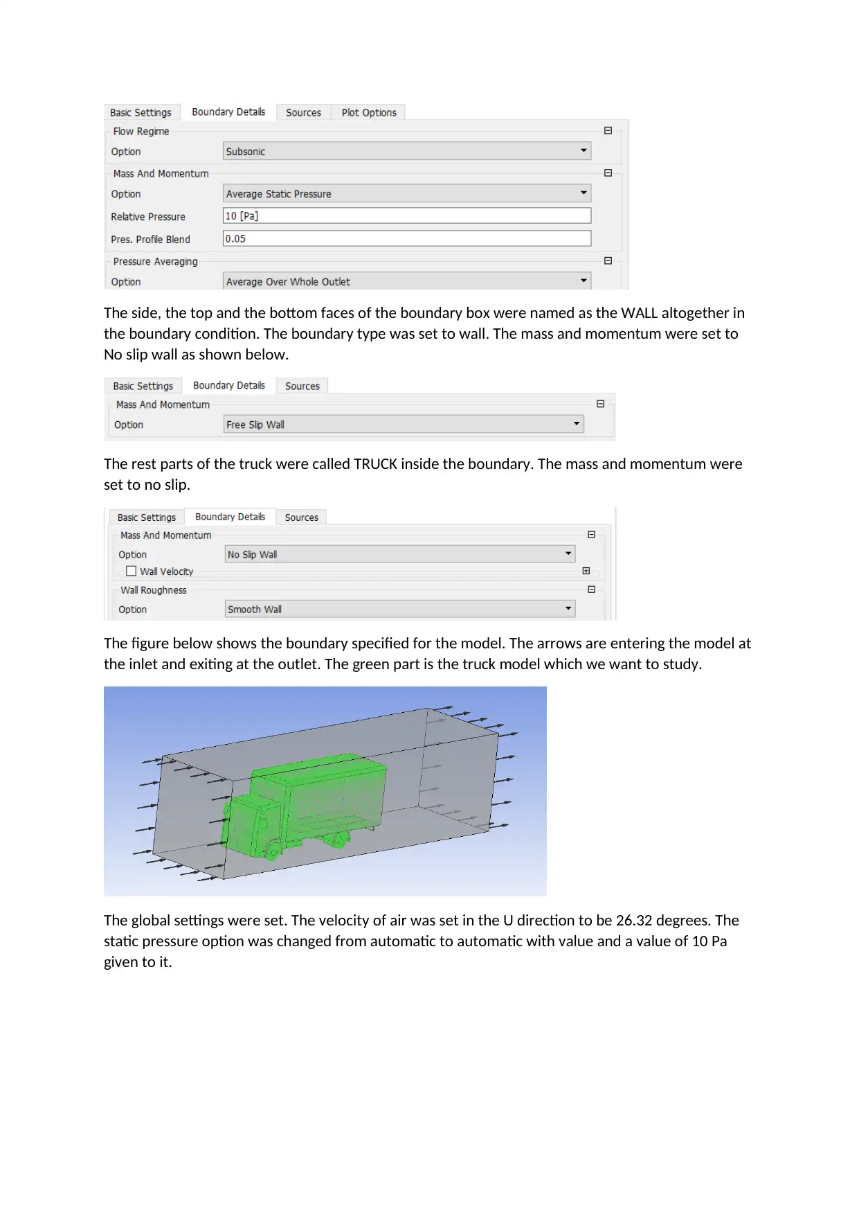
The side, the top and the bottom faces of the boundary box were named as the WALL altogether in
the boundary condition. The boundary type was set to wall. The mass and momentum were set to
No slip wall as shown below.
The rest parts of the truck were called TRUCK inside the boundary. The mass and momentum were
set to no slip.
The figure below shows the boundary specified for the model. The arrows are entering the model at
the inlet and exiting at the outlet. The green part is the truck model which we want to study.
The global settings were set. The velocity of air was set in the U direction to be 26.32 degrees. The
static pressure option was changed from automatic to automatic with value and a value of 10 Pa
given to it.
Paraphrase This Document
Need a fresh take? Get an instant paraphrase of this document with our AI Paraphraser
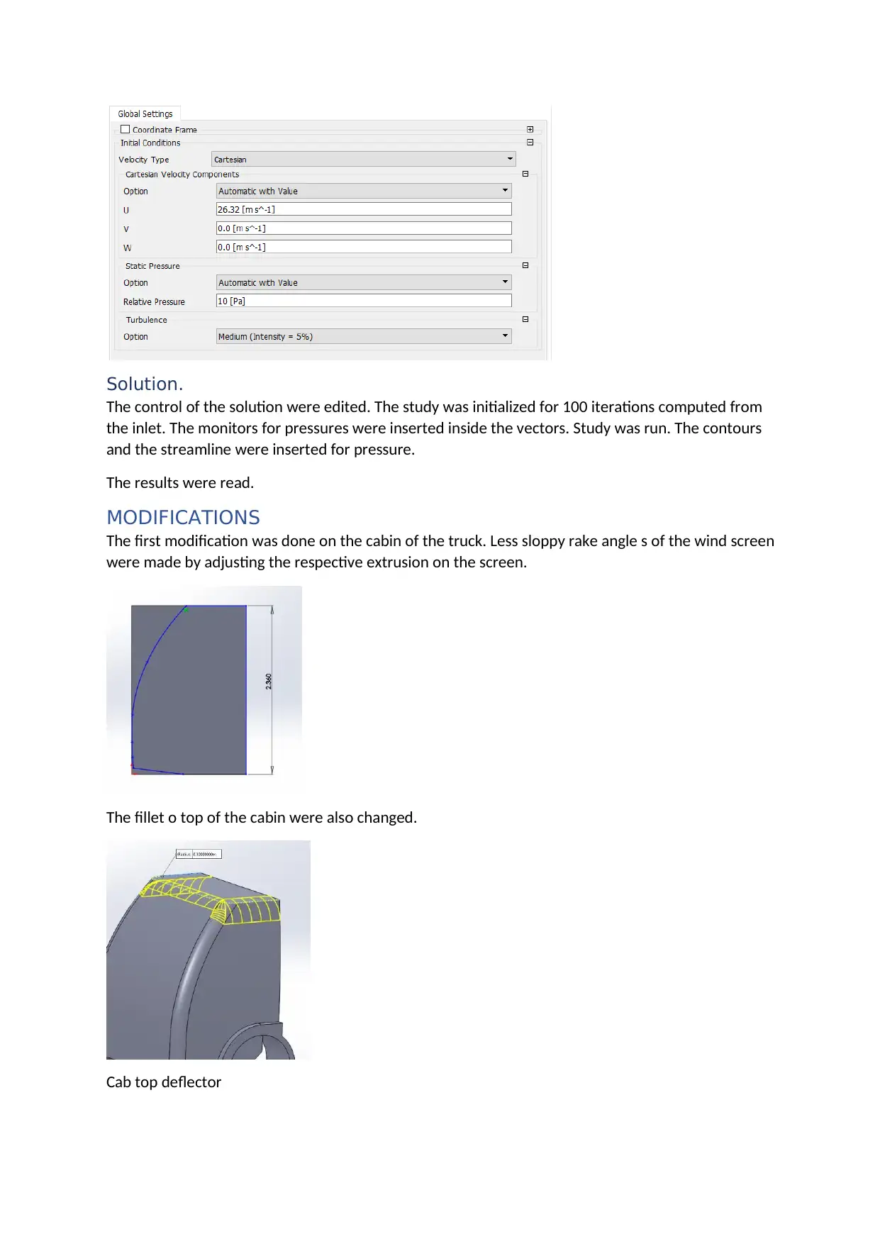
Solution.
The control of the solution were edited. The study was initialized for 100 iterations computed from
the inlet. The monitors for pressures were inserted inside the vectors. Study was run. The contours
and the streamline were inserted for pressure.
The results were read.
MODIFICATIONS
The first modification was done on the cabin of the truck. Less sloppy rake angle s of the wind screen
were made by adjusting the respective extrusion on the screen.
The fillet o top of the cabin were also changed.
Cab top deflector
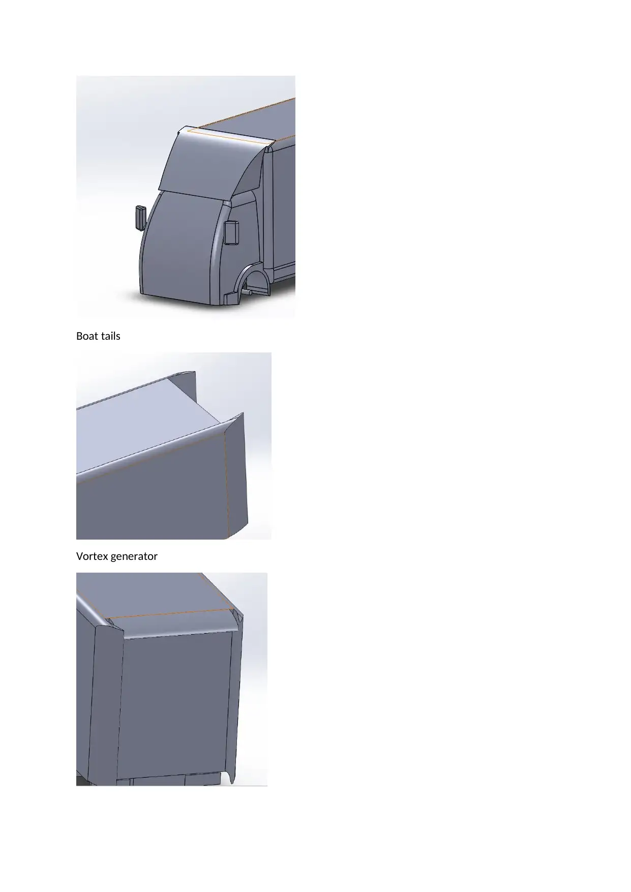
Boat tails
Vortex generator
Vortex generator
⊘ This is a preview!⊘
Do you want full access?
Subscribe today to unlock all pages.
Trusted by 1+ million students worldwide
1 out of 15
Related Documents


Your All-in-One AI-Powered Toolkit for Academic Success.
+13062052269
info@desklib.com
Available 24*7 on WhatsApp / Email
![[object Object]](/_next/static/media/star-bottom.7253800d.svg)
Unlock your academic potential
Copyright © 2020–2026 A2Z Services. All Rights Reserved. Developed and managed by ZUCOL.