Application and CFD Analysis of Screw Compressor using ANSYS Software
VerifiedAdded on 2022/11/14
|47
|12907
|3
Report
AI Summary
This report presents a comprehensive CFD analysis of a twin-screw air compressor, a positive displacement machine used for fluid and gas compression. The study employs ANSYS software to simulate the compressor's performance, focusing on rotor profile optimization and fluid dynamics within the helical grooves. The analysis investigates the impact of compressor speed, rotor profile, inlet temperature, and oil flow rate on compression efficiency. The research discusses the methodology, including the analytical algorithm for rotor profile generation and thermodynamic models. Results showcase pressure and velocity distributions under normal and non-normal operating conditions. The report highlights the importance of CFD in compressor design, emphasizing its role in optimizing performance, reliability, and efficiency. The study includes an overview of screw compressor applications, a literature review on compressor technology, and a detailed discussion of the methodology and findings. The report concludes with recommendations for further research and acknowledges the contributions of various individuals who supported the completion of the thesis.

CFD ANALYSIS OF SCREW
COMPRESSOR USING ANSYS
AUTHOR
YEAR
COMPRESSOR USING ANSYS
AUTHOR
YEAR
Paraphrase This Document
Need a fresh take? Get an instant paraphrase of this document with our AI Paraphraser
ABSTRACT
A twin-screw air compressor is basically a machine of positive displacement that is majorly used in the
compression of fluids and gases in order to control high pressures. It comprises of two similar
intermeshing rotors that both have helical grooves. The rotors also have a case that is perfectly fitting
which is separated from the rotors by the use of very tiny clearances. During the process of compression,
there are some types of rotors that are lubricated or applied with fluids or oil whereas there also exist
other types of rotors that are never applied such fluids or oil. Within the past few years after the invention
screw compressors, they have been largely and rapidly welcomed in the market. As a matter of fact, they
are also more preferred in the market over other types of machine that also perform positive displacement.
This is mainly due to their increased reliability, improved efficiency, increased service life, and increased
rotary speeds as well as higher compactness.
There has been development of several computer software and packages in order to effectively determine
and equally optimize the performances of the various profiles of these rotors. This probably represents a
major achievement given that previous experiments that have been carried were mainly to perform an
optimization of the performances of the different profiles of these rotors. Such experiments have proven
to be tedious and equally time-consuming. They are also not very accurate as compared to the improved
computer methods. This research work carries an analysis and discussion on the concept of using a
computer package for the purpose of optimizing a rotor profile.
The described procedure for the optimization of the twin-screw compressor is based on the
analytical algorithm for the generation of rotor profile that is combined with various models of the
thermodynamic processes and flow of fluid within the machine. Rotor profiles can be derived from a rack
that has both higher displacement and stronger female rotor lobes. The compressors that have been
designed therefore have an increased rate of delivery as well as improved efficiencies as compared to the
compressors that make use of highly known profiles. Some issues of optimization of the compressor ports
and the rotor profile have been discussed in this report. The discussions have used the 5/6-106 mm screw
compressor to help in illustrating the results. It is evident that the compressor speed, rotor profile, inlet
temperature and oil flow rate could possibly have a significant difference whenever various vapors or
gases are being compressed.
ACKNOWLEDGEMENTS
I would wish to thank the following people for their different roles in the completion of this thesis:
Professor Ibrahim Sultan Thanks for his guidance and supervision
Chanpreet Singh channi assisting and calculations
Prakash Dangal design and specifications
Karan saggu support in research
Gurnica Sidhu Help to write the thesis and Proofreading
DECLARATION OF ORIGINALITY
“I certify that except where due acknowledgement has been made, the work is that of the author alone; the
work has not been submitted previously, in whole or in part, to qualify for any other academic award; the
content of the thesis is the result of work which has been carried out since the official commencement
date of the approved research program,; and, any editorial work, paid or unpaid, carried out by a third
party is acknowledged.”
Name……………………………………………………………………………………………….…
Date………………………………………………… Sign………………………………………
⊘ This is a preview!⊘
Do you want full access?
Subscribe today to unlock all pages.
Trusted by 1+ million students worldwide
CONTENTS
Table of Contents
ABSTRACT....................................................................................................................................................2
ACKNOWLEDGEMENTS................................................................................................................................3
DECLARATION OF ORIGINALITY...................................................................................................................3
CONTENTS..................................................................................................................................................4
LIST OF TABLES............................................................................................................................................6
NOMENCLATURE.........................................................................................................................................6
LIST OF ABBREVIATIONS AND ACRONYMS..................................................................................................6
CHAPTER 1: INTRODUCTION........................................................................................................................7
OVERVIEW...............................................................................................................................................7
ROLE OF COMPUTATIONAL FLUID DYNAMIC IN COMPRESSOR ANALYSIS...............................................7
USES AND APPLICATIONS OF SCREW COMPRESSORS..........................................................................8
CHAPTER 2: LITERATURE REVIEW..............................................................................................................10
BACKGROUND THEORY ON COMPRESSORS..........................................................................................10
CLASSIFICATION OF COMPRESSORS..................................................................................................10
TWIN SCREW COMPRESSOR..............................................................................................................12
WORKING OF TWIN SCREW COMPRESSOR...........................................................................................15
GEOMETRY OF THE SCREW COMPRESSOR............................................................................................17
THE THERMODYNAMICS OF THE COMPRESSOR IN THE OPTIMIZATION CALCULATIONS......................18
DESIGN OF THE COMPRESSOR AND OPTIMIZATION OF THE ROTOR PROFILE.......................................20
GEOMETRICAL OPTIMIZATION OF A ROTARY COMPRESSOR FOR REFRIGERATORS..............................24
COMPRESSOR OPTIMIZATION...............................................................................................................28
CHAPTER 3: METHODOLOGY.....................................................................................................................31
ANALYSIS SPECIFICATION......................................................................................................................31
SCOPE OF THE ANALYSIS........................................................................................................................32
FINITE ELEMENT MODELING..............................................................................................................32
DEVELOPMENT OF CFD ANALYSIS.....................................................................................................33
THEORETICAL APPROACH......................................................................................................................33
CHAPTER 4: RESULTS.................................................................................................................................36
3D MODEL.............................................................................................................................................36
COMPUTATIONAL FLUID DYNAMICS RESULTS.......................................................................................36
Paraphrase This Document
Need a fresh take? Get an instant paraphrase of this document with our AI Paraphraser

NORMAL OPERATING CONDITIONS...................................................................................................36
CHAPTER 5: DISCUSSION...........................................................................................................................39
CHAPTER 6: CONCLUSIONS........................................................................................................................41
RECOMMENDATIONS FOR FURTHER WORK..........................................................................................43
CHAPTER 7: REFERENCES...........................................................................................................................44
LIST OF TABLES
Figure 1. construction of a reciprocating compressor...............................................................................11
Figure 2. Rotary vane compressor.............................................................................................................12
Figure 3. Parts of a twin screw compressor...............................................................................................12
Figure 4. Parts of a flooded screw compressor..........................................................................................13
Figure 5. Section through oil free compressor...........................................................................................14
Figure 6. Showing how the generating profile curves are distributed.......................................................18
Figure 7: Internal energy conversion equation..........................................................................................19
Figure 8.Showing an optimized rotor compressor for an oil-free compressor..........................................21
Figure 9: Showing an optimized rotor profile for an air free compressor..................................................22
Figure 10: Showing optimized rotor profile for an oil filled compressor...................................................22
Figure 11: showing an optimized rotor for refrigerator compressor duty.................................................22
Figure 12: Showing optimization calculation results for the different compressors..................................23
Figure 13: Specific variations in power for the compressors.....................................................................23
Figure 14: Showing the specific power as a function of compressor built-in volume and speed..............24
Figure 15: Showing the assembly of the electrical motor and pump for a basic rolling piston compresser
.................................................................................................................................................................. 25
Figure 16: Showing the geometrical constraints used during the study of optimization...........................29
Figure 17. Model modeled on Solidworks.................................................................................................36
Figure 18. Pressure distribution on the male screw at normal operating conditions................................37
Figure 19 velocity distribution of air inside the screw compressor...........................................................37
Figure 20.pressure distribution of air inside the screw compressor at non normal operating conditions.38
NOMENCLATURE
Pa Pascal. A unit of measurement of stress and pressure. 1 pascal is equal to 1 N/m2
M Bending Moment. (kN/m).
E Modulus of Elasticity
I Inertia. (m4)
T Torque
A Area. (m2)
B Backlash
J Second Polar moment of area
C
⊘ This is a preview!⊘
Do you want full access?
Subscribe today to unlock all pages.
Trusted by 1+ million students worldwide
D Diameter of rotor
L Length of rotorΝ Nusselt’s Number.
ℜ Reynolds number
Υ o
uo
hh Heat transfer coefficient
LIST OF ABBREVIATIONS AND ACRONYMS
FEM Finite Element Modeling
FEA Finite Element Analysis
CFD Computational Fluid Dynamics
CAD Computer Aided Design
CFX
L Length of rotorΝ Nusselt’s Number.
ℜ Reynolds number
Υ o
uo
hh Heat transfer coefficient
LIST OF ABBREVIATIONS AND ACRONYMS
FEM Finite Element Modeling
FEA Finite Element Analysis
CFD Computational Fluid Dynamics
CAD Computer Aided Design
CFX
Paraphrase This Document
Need a fresh take? Get an instant paraphrase of this document with our AI Paraphraser
CHAPTER 1: INTRODUCTION
OVERVIEW
Utilization of sustainable power source is one of major developing issues on the planet. Need of power
from sustainable sources and being put away in various structures is in the ascent. The power change
issues can influence the usefulness of the compressors. The structure of air compressors can take care of
this issue since air will be packed all through and power accessibility won't be an issue any longer.
The manufacturers of the screw compressor therefore need to know the operation and functioning of the
screw compressor. It is a requirement for the compressor manufacturers to specify the working
conditions, power rating, speed, compression ratio, efficiency and other factors. Such factors need to be
determined. In order to determine these properties, the manufacturer needs to model the compressor on a
CAD software, do finite element modeling and compute the air or liquid flow properties through the
compressor. Such properties cannot entirely be calculated by analytical methods only. Properties like
pressure distribution at various points when calculated analytically could take years to compute. The
solution would also be very big based on so many assumptions. These would lead to a prolonged design
period which would delay marketing and finally bring losses to the company. To avoid this, the design
engineers make use of FEA and CFD tools. One of which is Ansys. This utility programs enables the
designer to input the input data such as the model geometry and the boundary conditions or the initial
conditions. The programs compute the parameters which the design engineer require and then display the
results. The FEA and CFD properties can be solved through this method within a short time thus the
manufacturer will have ample time do the marketing.
ROLE OF COMPUTATIONAL FLUID DYNAMIC IN COMPRESSOR ANALYSIS
Computational liquid elements or CFD examination is one of the key investigation strategies utilized in
designing applications. The starting points of CFD lies in the humanity's endeavors to all the more likely
comprehend the intensity of common components like breeze, tempests, floods, or ocean waves.
The physical control of liquid elements advanced as the sciences began to characterize the common
power and related response of air, water or gases. This gave an efficient structure that grasped exact laws
and was gotten from stream estimation that is utilized to take care of handy issues. An ordinary liquid
elements issue includes fundamental liquid properties like mass flow rate, mass of air, density, and
temperature, in connection to flow.
In regular daily existence, we can discover fluid flow in meteorology, ventilation and cooling, streamlined
structure, motors ignition, or the human body—for instance, blood stream, etc.
Gas and fluid flow is evaluated by incomplete differential conditions speaking to protection laws for
mass, force, and vitality. Computational liquid elements is a part of liquid mechanics that utilizations
numerical examination and calculations to understand liquid streams circumstances. High-performing
PCs are utilized to direct the counts required to recreate the association of fluids and gases with surfaces
characterized by limit conditions.
CFD depends on the Navier-Stokes conditions. Emerging from applying Newton's second law of fluid
flow, together with the suspicion that the worry in the liquid is the aggregate of a diffusing thick term and
a weight term, these conditions depict how the speed, weight, temperature, and thickness of a moving
liquid are associated The advancement of CFD has been intently connected with the development of fast
PCs.
With a CFD examination, we can comprehend the fluid flow and thermal flow all through a system
including the screw compressor system. The fundamental system for any designing CFD examination
depends on a couple of methodology: Laws of material science for fluid flow and thermodynamics are
communicated as far as differential conditions, more often than not with many related factors. It happens
to be that a portion of the conditions for the two fields are comparable; for instance, the dispersion of a
scalar through a stream field and the dissemination of temperature.
USES AND APPLICATIONS OF SCREW COMPRESSORS.
A technology of piston type compressed air that is largely used in motor vehicles does convert the 4
stroke engine to a 2 stroke engine with valve timings of – 100 to 800, - 100 to 1500 and -100 to 1200. Its
travel is however limited to only 5km. “A compressed air driven piston engine offers a very resourceful
idea towards the development of compressed air technology. This is because its inlet valve opens and
closes at all times. The valve angle is therefore at 150 degrees leaving just 20 degrees for the purpose of
isentropic expansion. Whenever the exhaust valve has been moved, the piston gets from 150 degrees up
to 170 degrees. The final closing point for the exhaust is recorded at 340 degrees. The rate of flow of air
comparatively lower hence also makes the output of the engine lower (Cipollone, Contaldi, Bianchi, &
Murgia, 2013). The angle of the valve timing is subsequently made shorter. The piston type compressed
air engine on the other hand, offers valve timings for the intake valve as well as the exhaust opening and a
closing of 0° to 100° and another 180° to 300°. The intake valve and exhaust opening lifting is at 6mm
and 8mm during the course of the engine operating time. The main shortcoming from this system is the
reduced angles of the valves as well as the reduced mass rate of flow. Converting a petrol engine to a
⊘ This is a preview!⊘
Do you want full access?
Subscribe today to unlock all pages.
Trusted by 1+ million students worldwide

compressed air engine implies that the engine will receive air instead of petrol. The vehicle will
experimentally be able to move at a speed of 2km/h. the initial cylinder shape has to be changed to a two
sided lobed shape. The highest operating pressure is recorded at 4500 psi and at a weight of 18.5 kg.
Another shortcoming of this system is that it needs a lot of compressed air in order to run at a higher
mileage.” The required extensive piston cooling often leads to a longer operation time. The technology of
compressed air for a single cylinder engine has therefore attained a maximum speed recorded at 50 km/h.
Paraphrase This Document
Need a fresh take? Get an instant paraphrase of this document with our AI Paraphraser
CHAPTER 2: LITERATURE REVIEW
BACKGROUND THEORY ON COMPRESSORS
The theories which were applicable on compressors were developed in 1928 by Nahuse. He was a
Russian engineer at Novikov. However, his theories were not put in to practice until 1934 when the
world’s first practical compressor (Lysholm compressor) was built by a Sweden SRM (Svenska Rotor
Maskiner AB). The compressor was first used industrially since 1955. The first testing of the screw
compressor was done in the same year by the James Howden & company. The first twin screw
compressor was introduced in 1960. It was small size, cheaper, had high volume capacity and offered
high compression ratios.
CLASSIFICATION OF COMPRESSORS
A compressor is a device used to increase the gas pressure in a system by decreasing the volume of air
mechanically. Most compressors compress air but nitrogen, oxygen and natural gas which have become
industrially important are also compressed. There are three major categories of compressors namely;
i. Rotary Vane Compressors
ii. Reciprocating, Piston Compressors
iii. Rotary Screw Compressors.
The reciprocating compressors are found in mobile applications and are the most common. It is a positive
displacement machine. It uses pistons to compress the gas and deliver it at high pressures. Most of
application for this type of compressors are in the oil and gas industry. Petroleum treatment facilities
utilize these compressors for forms that require high pressure conveyance of fundamental petroleum has.
The flammable gas industry likewise uses these compressors to move gas by means of pipelines to other
parts of the country. These compressors can likewise be found in compound plants, refrigeration plants,
or air compressors for tooling. Th figure below shows the construction of a reciprocating compressor. The
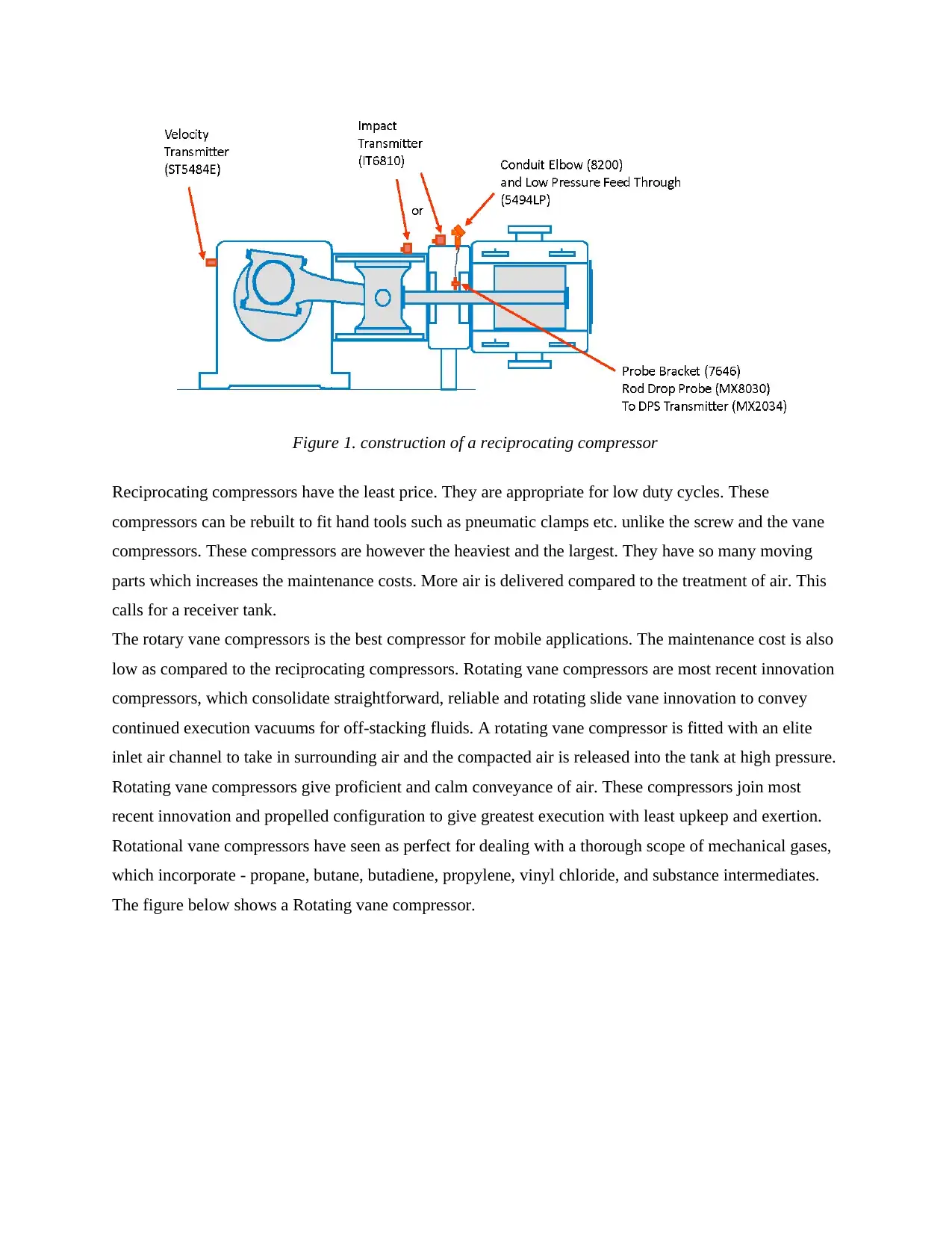
Figure 1. construction of a reciprocating compressor
Reciprocating compressors have the least price. They are appropriate for low duty cycles. These
compressors can be rebuilt to fit hand tools such as pneumatic clamps etc. unlike the screw and the vane
compressors. These compressors are however the heaviest and the largest. They have so many moving
parts which increases the maintenance costs. More air is delivered compared to the treatment of air. This
calls for a receiver tank.
The rotary vane compressors is the best compressor for mobile applications. The maintenance cost is also
low as compared to the reciprocating compressors. Rotating vane compressors are most recent innovation
compressors, which consolidate straightforward, reliable and rotating slide vane innovation to convey
continued execution vacuums for off-stacking fluids. A rotating vane compressor is fitted with an elite
inlet air channel to take in surrounding air and the compacted air is released into the tank at high pressure.
Rotating vane compressors give proficient and calm conveyance of air. These compressors join most
recent innovation and propelled configuration to give greatest execution with least upkeep and exertion.
Rotational vane compressors have seen as perfect for dealing with a thorough scope of mechanical gases,
which incorporate - propane, butane, butadiene, propylene, vinyl chloride, and substance intermediates.
The figure below shows a Rotating vane compressor.
⊘ This is a preview!⊘
Do you want full access?
Subscribe today to unlock all pages.
Trusted by 1+ million students worldwide
1 out of 47
Related Documents


Your All-in-One AI-Powered Toolkit for Academic Success.
+13062052269
info@desklib.com
Available 24*7 on WhatsApp / Email
![[object Object]](/_next/static/media/star-bottom.7253800d.svg)
Unlock your academic potential
Copyright © 2020–2026 A2Z Services. All Rights Reserved. Developed and managed by ZUCOL.