CFD Analysis for Enhanced Heat Transfer in Circular Fins

Verified

Added on  2023/03/30

|21
|2668
|323
Report
AI Summary
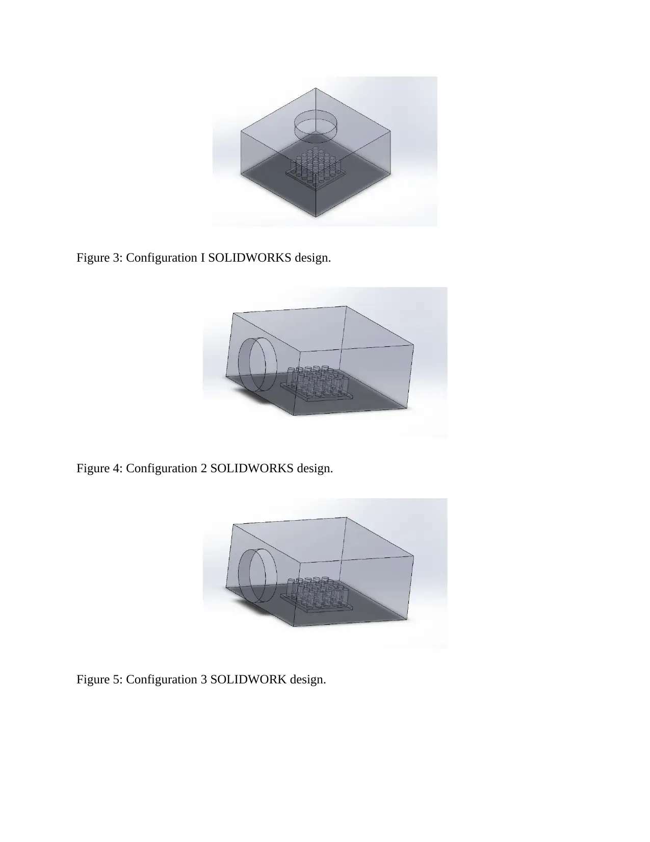
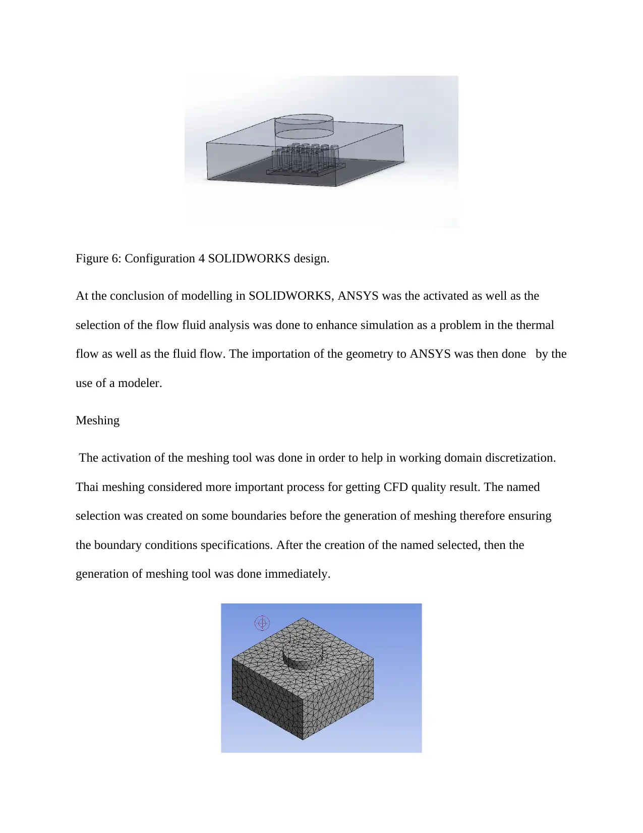
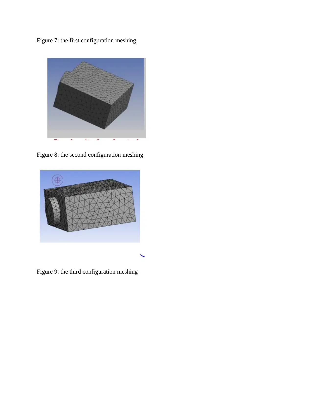
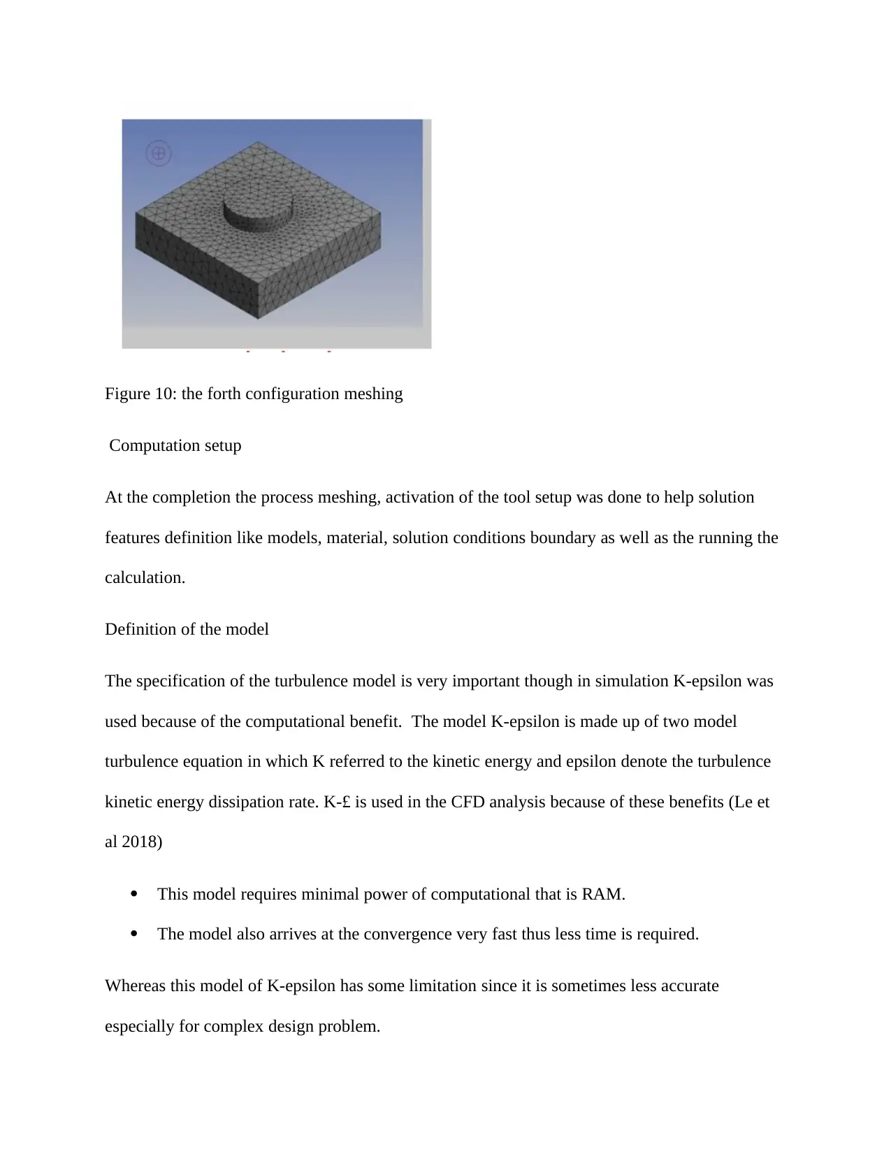
This report presents a comprehensive CFD analysis of heat transfer in circular fins, aiming to identify the optimal fin configuration for maximizing heat transfer and cooling rates. The study investigates various configurations, including air inlet geometries from the top and sides. The analysis leverages the principles of convection, as described by Newton's law of cooling, and employs computational fluid dynamics (CFD) to simulate heat transfer under different conditions. The CFD simulation process involves geometry design in SOLIDWORKS, meshing, and computational setup using ANSYS FLUENT. The K-epsilon turbulence model is used for its computational efficiency. The report details the meshing process, model definitions, material properties, and boundary conditions for each configuration. Results from the simulations, including velocity vectors, temperature contours, and streamline velocities, are presented and discussed to evaluate the performance of each fin configuration. The study concludes by comparing the thermal performance of the configurations and identifying the most effective design for cooling electronic components.
Document Page
CFD
By Name
Course
Instructor
Institution
Location
Date
tabler-icon-diamond-filled.svg

Paraphrase This Document

Need a fresh take? Get an instant paraphrase of this document with our AI Paraphraser
Document Page
Introduction
The transfer of heat can be referred a unique process whereby the internal energy of the object is
passed to any other. This transfer of heat may happen within three different ways including
convection, radiation and conduction. Conduction is the type of heat transfer where the
molecules agitation take place in the solid particles. While convection is where the molecules
agitation take place in fluids due to mass flow. Radiation is the transfer of heat through the
electromagnetic waves (Strasser, Battaglia and Walters 2015). The heat transfer that occurred in
fins is always facilitated convection transfer mode. the report consists of the analysis of transfer
of heat for the circular fin within the various configurations in order to achieve the creation of
the best fin configuration that aims in producing the highest rate of heat transfer as well as the
highest cooling rate. This configuration consists of air inlet geometry from the top as well as the
remaining sides of the wall and the inlet of the air on one side as the air enters the three
remaining sides.
According to the newton cooling law governing the transfer of heat within the solid that is the
surfaces having fins and the moving fluid such as air. This law state that the rate at which a body
loss heat is always proportional directly to temperature variation between its surrounding and the
body convectively as in the equation Q = hA(Ts-T), in which Tso stands for the surface
temperature while T∞ is the fluid temperature. Thus the convective heat transfer of heat is
increased when the variation in temperature is increased, thus leading to an increase in
convection coefficient h as well as the increase in the contact surface area. This because an
increase in coefficient h and the temperature differences are not under the control of a man. So
the most efficient way of increasing the transfer of heat is through the use of an extended surface
such as fins.
Document Page
Therefore, fins are considered as protrusions that are extended from the base surface (heat
source) unto to the fluid to be cooled that is the air foe electronic device within the motion. This
protrusion fins cause an increase in the area of the surface connected with the moving fluid.
While cooling extended surface for fins creates a huge range of the automobile radiators, air
conditioning equipment, electronic generator engines and motorcycles engines. While the main
function of the fin is to raise the cooling surface area.
Methods
the CFD analysis
The aim of the project is to get the most appropriate surface extruded configuration which will
give a room of the best cooing for an electric component of an experience of around 100W of
heat as well as implementing the cooling of air. While the flowing air having the temperature of
20 degrees Celsius and 2m/s as the velocity (Salary et al 2017). The computational dynamics of
fluid was selected from the experimental method because of its many merits such as the result
generation is faster, gives high accurate result, cheaper and very reliable. Computational fluid
dynamics had been considered effective especially to the extensive project design like the
engines of jet since it is highly reliable. The CFD simulation process involves the three steps
such as the geometry, definition, pre-processing that is the calculation set up, meshing as well as
calculation running) aa well as the processes done of the procedure.
CFD uses numerical methods in getting the approximate solutions to these problems that affect
the transfer of heat, mass flow as well as fluid flow (Pinto et al 2017). CFD uses the governing
equation as a guide to the solver during the solution calculation. These governing equation
includes mass conservation, momentum conservation and the nervier strokes. While Naiver-
Document Page
stroke is applied in this simulation as consist of the mass momentum and mass conservation. The
governing equation is applying in physical challenges discretization has to be done. The
discretization procedure consists of subdividing the domain challenges to finite element as when
using the governing equations in solving every element individually therefore the integration can
be done later hence offering the solution overall (Strasser, Battaglia and Walters 2015).
The following configuration was used to guide computation whine finding the model which may
result to the lowest fins temperature.
The inlet put on the box top while the other four are taken as the exit
The air inlet located on the boundary of one side while an outlet in the on the boundary opposite
and remaining side are the solid walls
The air inlet on boundary of one side as the air flow to the all sides of the three boundaries.
Modeling geometry
The problem solution on the fluid flow is done during the SOLIDWORK geometry designing.
Since examination of many configurations done in different designs to be modelled within the
SOLIDWORKS. ANSYS FLUENT was thereafter applied in doing the numerical analysis.
tabler-icon-diamond-filled.svg

Paraphrase This Document

Need a fresh take? Get an instant paraphrase of this document with our AI Paraphraser
Document Page
Figure one: the whole fin setup
Figure 2: fin that is designed in mm
This challenge requires that simulation be conducted into four configurations to facilitate the
determination of the most efficient configuration. Many model representing the problem therefor
were modeled within the SOLIDWORKS as follows.
Document Page
Figure 3: Configuration I SOLIDWORKS design.
Figure 4: Configuration 2 SOLIDWORKS design.
Figure 5: Configuration 3 SOLIDWORK design.
Document Page
Figure 6: Configuration 4 SOLIDWORKS design.
At the conclusion of modelling in SOLIDWORKS, ANSYS was the activated as well as the
selection of the flow fluid analysis was done to enhance simulation as a problem in the thermal
flow as well as the fluid flow. The importation of the geometry to ANSYS was then done by the
use of a modeler.
Meshing
The activation of the meshing tool was done in order to help in working domain discretization.
Thai meshing considered more important process for getting CFD quality result. The named
selection was created on some boundaries before the generation of meshing therefore ensuring
the boundary conditions specifications. After the creation of the named selected, then the
generation of meshing tool was done immediately.
tabler-icon-diamond-filled.svg

Paraphrase This Document

Need a fresh take? Get an instant paraphrase of this document with our AI Paraphraser
Document Page
Figure 7: the first configuration meshing
Figure 8: the second configuration meshing
Figure 9: the third configuration meshing
Document Page
Figure 10: the forth configuration meshing
Computation setup
At the completion the process meshing, activation of the tool setup was done to help solution
features definition like models, material, solution conditions boundary as well as the running the
calculation.
Definition of the model
The specification of the turbulence model is very important though in simulation K-epsilon was
used because of the computational benefit. The model K-epsilon is made up of two model
turbulence equation in which K referred to the kinetic energy and epsilon denote the turbulence
kinetic energy dissipation rate. K-£ is used in the CFD analysis because of these benefits (Le et
al 2018)
This model requires minimal power of computational that is RAM.
The model also arrives at the convergence very fast thus less time is required.
Whereas this model of K-epsilon has some limitation since it is sometimes less accurate
especially for complex design problem.
Document Page
The definition of material
To carry out the simulation, the there is need for the solver to acknowledge the component
material properties. The fin and the based should be put on an aluminum material whereas the
part is fluid domain thus allowing the fluid to flow. The fluid material domain with air
specifications since the electronic element get cooled. Also aluminum from the material library is
added.
The conditions of the boundary
Configuration 1
The inlet of the first configuration is located on the top. The boundary of the inlet is said to have
2m/s as the velocity with 297K temperatures as the material fluid is specified as the air. The fin
as well as the fin areas specified as the without any slip property while well-defined aluminum
material having heat flux of 3168.4 w/m2(the calculation of heat flux done and explained in the
next three sections). The intensity of the turbulence inlet is set to be 1%. While the outlet
surfaces consist of four walls box as the boundary is defined as the outlet pressure with zero
gradient with the turbulence outlet intensity set to be 5%( Kapopara et al 2016).
Configuration 2
Both the base and the fin surface area was specified on mom slip wall as well as aluminum
material of 3168.4w/m2 flux of heat. An inlet surface put one of the walls of box while the outlet
on the wall of the opposite side. The adjacent boundaries are located as the solid walls without
slip property. The velocity of the inlet boundary was discovered up to 2m/s with 293 k
temperatures and the intensity of turbulence of 1% whereas the outlet boundary having pressure
of the outlet of 5% intensity of the turbulence.
tabler-icon-diamond-filled.svg

Paraphrase This Document

Need a fresh take? Get an instant paraphrase of this document with our AI Paraphraser
Document Page
Configuration 3
the outlet is at the side of the box boundary and the remaining side taken as the outlets in this
configuration. The conditions of the boundary are as mention above.
Configuration 4
It has a similar definition as configuration 1though the difference consist of geometry since
because of having top boundary moved down to 50mm higher than the base level.
The running calculation.
The calculations of the setup were done using 50 iterations number
Document Page
Results
The various result from the various configurations such as velocity vectors, fin contours
temperature as well as the streamline velocity presented in the section
First Configuration
The inlet of the air is located at the top while the outlets are set on the other four sides of the box
as the below illustration
chevron_up_icon
1 out of 21
circle_padding
hide_on_mobile
zoom_out_icon
[object Object]