NEF4102 - CFD Simulation of Air Movement in IC Engine Cylinder
VerifiedAdded on 2023/06/12
|19
|4844
|295
Project
AI Summary
This project presents a computational fluid dynamics (CFD) simulation of air movement inside the cylinder of an internal combustion (IC) engine. It begins with a literature review, examining engine and piston designs, focusing on the evolution of materials and the impact of piston crown shapes on combustion. The review covers studies analyzing piston geometry effects on flow distribution, turbulence, and velocity flows within the combustion chamber during intake and compression strokes. Various CFD methodologies, including port flow analysis, full cycle simulation, and cold flow analysis, are discussed. The project emphasizes the importance of understanding fluid motion for efficient air-fuel mixing and improved combustion, exploring parameters like turbulence, swirl, and tumble. Governing equations in CFD, including continuity, momentum, and energy equations, are also mentioned. Desklib offers a platform for students to access this project and other solved assignments.

CFD simulation 1
CFD SIMULATION OF AIR MOVEMENT INSIDE THE CYLINDER OF AN INTERNAL
COMBUSTION
By Name
Course
Instructor
Institution
Location
Date
CFD SIMULATION OF AIR MOVEMENT INSIDE THE CYLINDER OF AN INTERNAL
COMBUSTION
By Name
Course
Instructor
Institution
Location
Date
Paraphrase This Document
Need a fresh take? Get an instant paraphrase of this document with our AI Paraphraser
CFD simulation 2
LITERATURE REVIEW
The engines and piston design
The engines and piston uses small skirts since they grow shorter and lighter with
evolution. Currently, pistons are built from aluminium alloys as opposed to silicon that
lowers thermal expansion and improves resistance (Guzzella & Onder, 2009). The
introduction of piston “tops” with bowl like tops that is subjected to the combustion chamber
giving it different effects in the heating process. Primarily the piston crown act as the burning
chamber since the diesel has no ignition phase. This improves the combustion ratio. Gasoline
engines have employed the use of advanced crowned pistons. The fuel and air motion are
managed by the pistons bowl design during compression stroke before ignition (Stone, 2009)
Bowl shaped piston design creates perfect turbulence mixture of air and fuel for
efficient combustion generating more power for the engine processes. Bowls are designed
with different shapes for effective fuel consumption (Chellen & Baranescu, 2010). The use of
gasoline has led to the spread of bowled pistons. The low conditions in high-speed direct
injection engines at the end of compression stoke, near top dead centre have become
critical .Air flow into the cylinder and intake valves in the induction process and its
evaluation in the compression stroke is used to determine the combustion process
(Rakopoulos & Giakoumis, 2016)
More researches and studies have been conducted on the geometry of the piston to
asses on issues affecting the flow distribution of diesel engines. The project chapter is used to
analyse previous published works that lays a foundation for more work research in this
CFD simulation 3
project. This gives a proper understanding of the research topics and gives a guide throughout
the work process. The engine cylinder flow characteristics with different pistons designs were
analysed (Ozsezen etal, 2009)
Due to this, the intake and compression stroke analysis have been undertaken at
realistic operating conditions and proper turbulence and velocity flows generated in every
combustion chamber verified in details (Taylor, 2009). Analysis shows that the geometry of
the piston had a small effect on in-cylinder flow at the beginning of the compression stroke
and the intake stroke. The bowl shaped piston is of great importance at the TDC and at the
start of the expansion stroke as it regulates the turbulence velocity fields and ensemble-
average mean (Rakopoulos etal, 2017)
The turbulence or swirl motion of the engine cylinder during the compression and
intake strokes of the pistons geometry construction with a single intake valve had been
analysed and studied (Som & Datta, 2018), though a small validation presentation has been of
the analysis and calculation made. Full calculation of the analysis and solutions of the
compression and intake processes have been conducted and analysed by Chen et al who
presented the calculations and compared the performance of the engine with experimental
results obtained from conducted analysis (Rakopoulos etal, 2011)
From the data has been used to indicate that the calculated results were used to predict
the turbulence velocity flow. Comparisons of the results with the real geometry were used to
explain the error differences in the experimental data and the disadvantages of the standard
k–ɛ model. In addition to that, Dillies et al conducted a study and too presented the same
calculation analysis of a diesel engine having a single intake valve for a single combustion
chamber, the case which data was correctly merging well with the conducted experimental
⊘ This is a preview!⊘
Do you want full access?
Subscribe today to unlock all pages.
Trusted by 1+ million students worldwide
CFD simulation 4
results. A computational review cited on large eddy simulation was done (Benjumea &
Agudelo, 2009)
Computational fluid dynamics
The computational fluid dynamics analysis applies an integration of computational
software, mathematical modelling and numerical methods in order to visualize and give a
prediction of both the quantitative and the qualitative characteristics of fluid flows (Anderson
& Wendt, 2015 )(Niu etal, 2010). This tool has the capability of providing various solutions
such as the multi-phase and single phase conditions isothermal flow, a chemical reaction in
fluid flow as well as the incompressible or compressible fluid flow (Chung, 2010).
In our daily experiences, we experience various circumstances involving fluid flow
and the computational fluid dynamics analysis tool has been applied while performing the
analysis of the air conditioning, engine combustion, ventilation as well as the propulsion
system (Versteeg & Malalasekera, 2009). For the internal combustion, there exist four
methodologies which differ from one another with regards to the results of the operators.
These methods include
In-cylinder combustion simulation (Kollmann, 2012)
Port flow analysis (Sayma, 2009)
Full cycle simulation (Roache, 2011)
Cold flow analysis (Hu, 2012)
Port flow analysis
In this method, depending on the selection of the operator, the engine configuration is
held frozen at a certain engine cycle angle. This technique is very significant and is very
Paraphrase This Document
Need a fresh take? Get an instant paraphrase of this document with our AI Paraphraser
CFD simulation 5
crucial when it comes to the static analysis mostly in problems involving the computational
fluid dynamics (Huang etal, 2015). The CFD operators are provided an option of either the
full cycle simulation or the combustion simulation that’s for the CFD simulation (Lin etal,
2009).Nevertheless, when it comes to the in-cylinder combustion simulation, the simulation
is only done for the power stroke (Versteeg & Malalasekera, 2014). Whereas for the full
cycle simulation the analysis that is obtained has the possibility of offering the full picture
of the processes occurring in the engine such as the injection of fuel, exhaust gases generated
from the chemical reaction, modelling of the air that’s flowing inside the cylinder and also
the combustion (Anderson &Wendt 2015).
Cold flow simulation
The cold flow simulation can either as well categorized as transient simulation (Van
wachem etal ,2011). Here, there is the possibility of carrying out a simulation of the full
engine cycle without getting a capture of the chemical reaction (Kloss etal, 2012). This
technique has the ability to visualize the flow of air throughout the system thereby capturing
the air which is being induced and tentatively give a prediction of the swirl formation, tumble
formation as well as the formation of squish (Jacobsen etal, 2012). Besides, the prediction of
the mixing of the fuel that has been injected with air can also be done (Li etal,2009)
The assumptions that are made in this simulation includes the changes in the
thermodynamics of the engine, the exhaust stroke flow, and the power stroke flow
(Karniadakis & Sherwin, 2013). Some of the equation which declines the energy, momentum,
k epsilon and mass devoid the chemical reaction and the injection of the fuel include
(Lijewski & Suhs, 2014)
crucial when it comes to the static analysis mostly in problems involving the computational
fluid dynamics (Huang etal, 2015). The CFD operators are provided an option of either the
full cycle simulation or the combustion simulation that’s for the CFD simulation (Lin etal,
2009).Nevertheless, when it comes to the in-cylinder combustion simulation, the simulation
is only done for the power stroke (Versteeg & Malalasekera, 2014). Whereas for the full
cycle simulation the analysis that is obtained has the possibility of offering the full picture
of the processes occurring in the engine such as the injection of fuel, exhaust gases generated
from the chemical reaction, modelling of the air that’s flowing inside the cylinder and also
the combustion (Anderson &Wendt 2015).
Cold flow simulation
The cold flow simulation can either as well categorized as transient simulation (Van
wachem etal ,2011). Here, there is the possibility of carrying out a simulation of the full
engine cycle without getting a capture of the chemical reaction (Kloss etal, 2012). This
technique has the ability to visualize the flow of air throughout the system thereby capturing
the air which is being induced and tentatively give a prediction of the swirl formation, tumble
formation as well as the formation of squish (Jacobsen etal, 2012). Besides, the prediction of
the mixing of the fuel that has been injected with air can also be done (Li etal,2009)
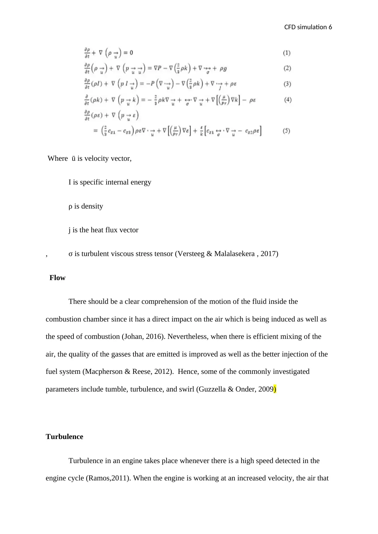
The assumptions that are made in this simulation includes the changes in the
thermodynamics of the engine, the exhaust stroke flow, and the power stroke flow
(Karniadakis & Sherwin, 2013). Some of the equation which declines the energy, momentum,
k epsilon and mass devoid the chemical reaction and the injection of the fuel include
(Lijewski & Suhs, 2014)
CFD simulation 6
Where ū is velocity vector,
I is specific internal energy
ρ is density
j is the heat flux vector
, σ is turbulent viscous stress tensor (Versteeg & Malalasekera , 2017)
Flow
There should be a clear comprehension of the motion of the fluid inside the
combustion chamber since it has a direct impact on the air which is being induced as well as
the speed of combustion (Johan, 2016). Nevertheless, when there is efficient mixing of the
air, the quality of the gasses that are emitted is improved as well as the better injection of the
fuel system (Macpherson & Reese, 2012). Hence, some of the commonly investigated
parameters include tumble, turbulence, and swirl (Guzzella & Onder, 2009)
Turbulence
Turbulence in an engine takes place whenever there is a high speed detected in the
engine cycle (Ramos,2011). When the engine is working at an increased velocity, the air that
⊘ This is a preview!⊘
Do you want full access?
Subscribe today to unlock all pages.
Trusted by 1+ million students worldwide
CFD simulation 7
gets in and out of the cylinder is at a higher velocity thereby resulting in the generation of
turbulence inside the cylinder (Turbocharging, 2010). This turbulent flow which is
developed plays a significant role when it comes to determining some various factors
including the fuel-air mixture, combustion in the engine cycle, evaporation and the heat
transfer (Daw etal, 2015). Hence, it is a requirement for the designers to come up with
efficient designs which will be able to withstand the pressure even at a top dead center (Han
& Reitz, 2013)
The reason as to why is because when the ignition takes place at an increased pace
and near the top dead center, there is increased spread of the flame and rapid break up when
compared to when there is low turbulence (Cook & Powell, 2012). In the past, some
researchers suggested that the design of the combustion chamber is very significant in
influencing the turbulence that will be generated in the engine (Balluchi etal, 2010). Besides,
there are other factors which influence the generation of the turbulence (Nikkhajoei &
Lasseter, 2009). They include speed of the piston, design of the intake manifold and the
condition of the inlet flow. There is also the design of the valves and the tumble flap
(Patterson & Reitz, 2013). The turbulent kinetic energy is one of the actors that can be easily
simulated through the CFD (Kokjohn etal, 2010).
Swirl
The swirl refers to the rotational motion of the air around the vertical axis of the
cylinder (Gupta & Syred, 2014). Being one of the factors that influence the transfer of heat,
quality of combustion, the in-cylinder fluid movement (Huang & Yang, 2009). When this
parameter is combined with tumble, then the overall resulting turbulence in the engine is very
high and this can be retained in the compression stroke (Voronkov, 2015). The nature of the
swirl often is not easy to determine in prior and one of the techniques which are applied in the
Paraphrase This Document
Need a fresh take? Get an instant paraphrase of this document with our AI Paraphraser
CFD simulation 8
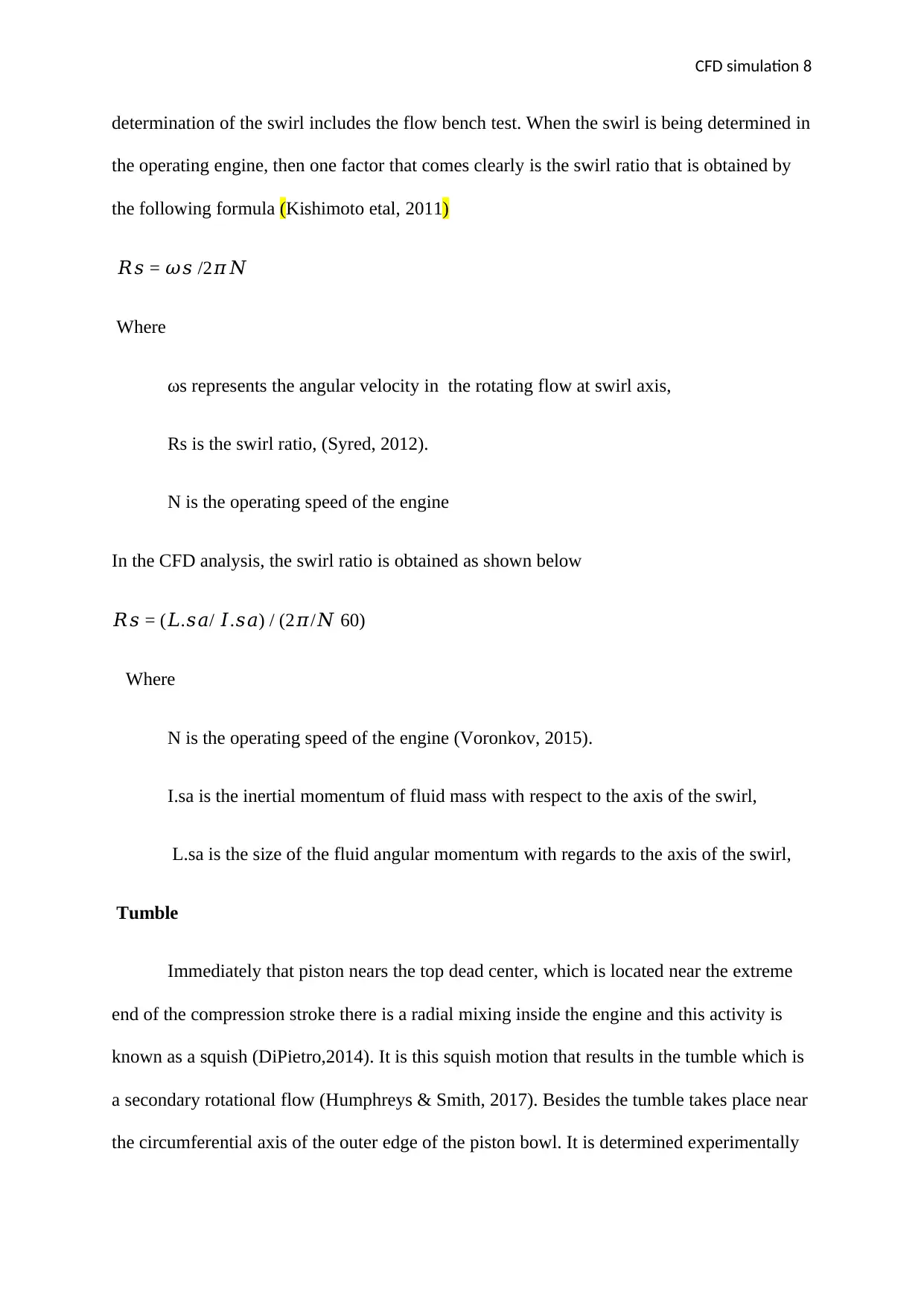
determination of the swirl includes the flow bench test. When the swirl is being determined in
the operating engine, then one factor that comes clearly is the swirl ratio that is obtained by
the following formula (Kishimoto etal, 2011)
𝑅𝑠 = 𝜔𝑠 /2𝜋𝑁
Where
ωs represents the angular velocity in the rotating flow at swirl axis,
Rs is the swirl ratio, (Syred, 2012).
N is the operating speed of the engine
In the CFD analysis, the swirl ratio is obtained as shown below
𝑅𝑠 = (𝐿.𝑠𝑎/ 𝐼.𝑠𝑎) / (2𝜋/𝑁 60)
Where
N is the operating speed of the engine (Voronkov, 2015).
I.sa is the inertial momentum of fluid mass with respect to the axis of the swirl,
L.sa is the size of the fluid angular momentum with regards to the axis of the swirl,
Tumble
Immediately that piston nears the top dead center, which is located near the extreme
end of the compression stroke there is a radial mixing inside the engine and this activity is
known as a squish (DiPietro,2014). It is this squish motion that results in the tumble which is
a secondary rotational flow (Humphreys & Smith, 2017). Besides the tumble takes place near
the circumferential axis of the outer edge of the piston bowl. It is determined experimentally
CFD simulation 9
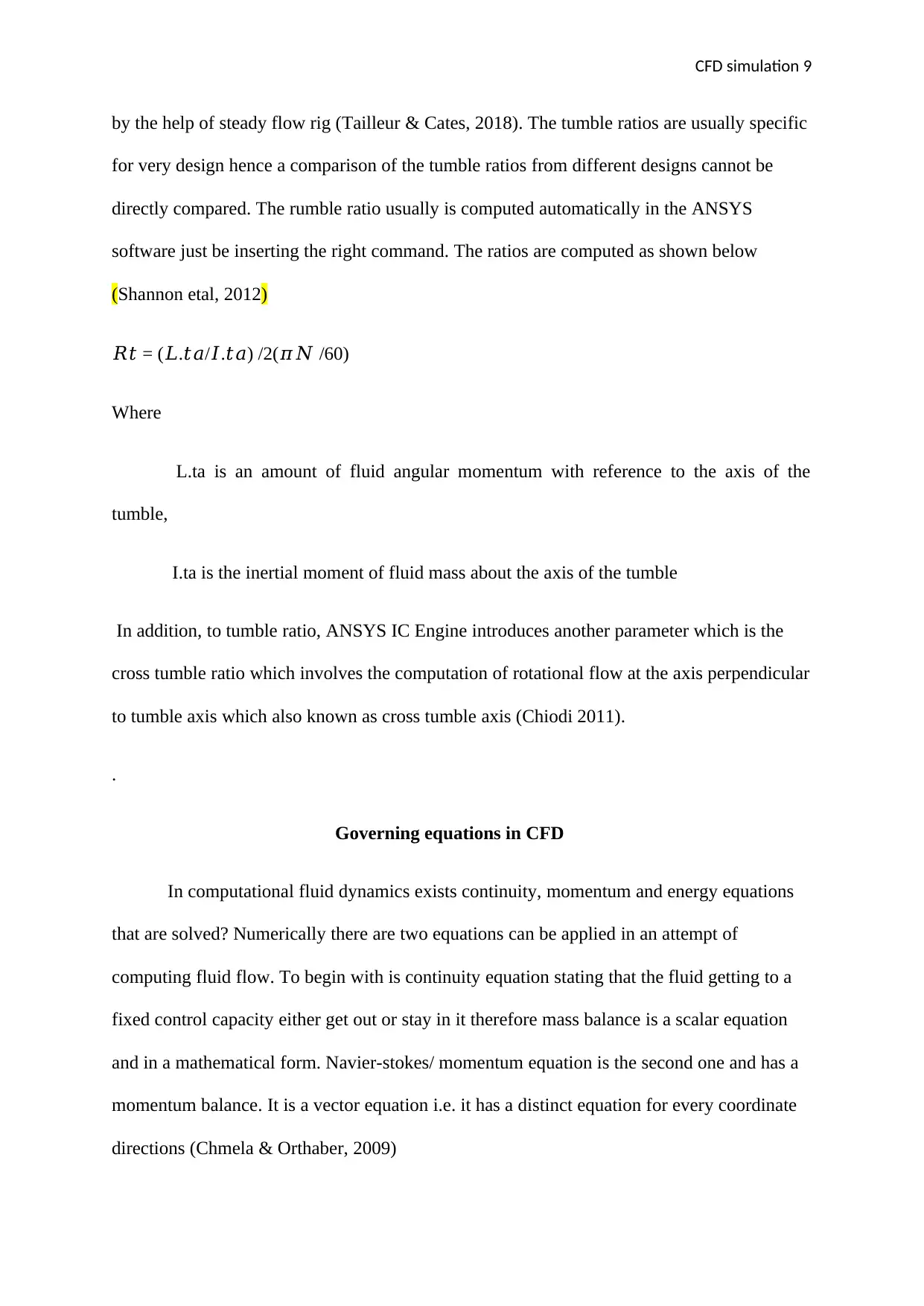
by the help of steady flow rig (Tailleur & Cates, 2018). The tumble ratios are usually specific
for very design hence a comparison of the tumble ratios from different designs cannot be
directly compared. The rumble ratio usually is computed automatically in the ANSYS
software just be inserting the right command. The ratios are computed as shown below
(Shannon etal, 2012)
𝑅𝑡 = (𝐿.𝑡𝑎/𝐼.𝑡𝑎) /2(𝜋𝑁 /60)
Where
L.ta is an amount of fluid angular momentum with reference to the axis of the
tumble,
I.ta is the inertial moment of fluid mass about the axis of the tumble
In addition, to tumble ratio, ANSYS IC Engine introduces another parameter which is the
cross tumble ratio which involves the computation of rotational flow at the axis perpendicular
to tumble axis which also known as cross tumble axis (Chiodi 2011).
.
Governing equations in CFD
In computational fluid dynamics exists continuity, momentum and energy equations
that are solved? Numerically there are two equations can be applied in an attempt of
computing fluid flow. To begin with is continuity equation stating that the fluid getting to a
fixed control capacity either get out or stay in it therefore mass balance is a scalar equation
and in a mathematical form. Navier-stokes/ momentum equation is the second one and has a
momentum balance. It is a vector equation i.e. it has a distinct equation for every coordinate
directions (Chmela & Orthaber, 2009)
⊘ This is a preview!⊘
Do you want full access?
Subscribe today to unlock all pages.
Trusted by 1+ million students worldwide
CFD simulation 10
.
Transient IC engine analysis
While conducting analysis of IC engine dynamics, model of meshed manifold together with
burning chamber is inserted to ANSYS Fluent 13.0. The CFD simulation is for cold flow
where heat is not needed (Dinler & Bucel, 2016).
.
Boundaries and initial conditions
The intake and exhaust manifolds need a constant pressure. Next to cells above/ below the
valve are the attach boundaries specified on coincident cell face. Logarithmic law is applied
to reduce the slipping and heat loss by the walls of the engine without a boundary
(Rakopoulos et al, 2010).
Mathematical model
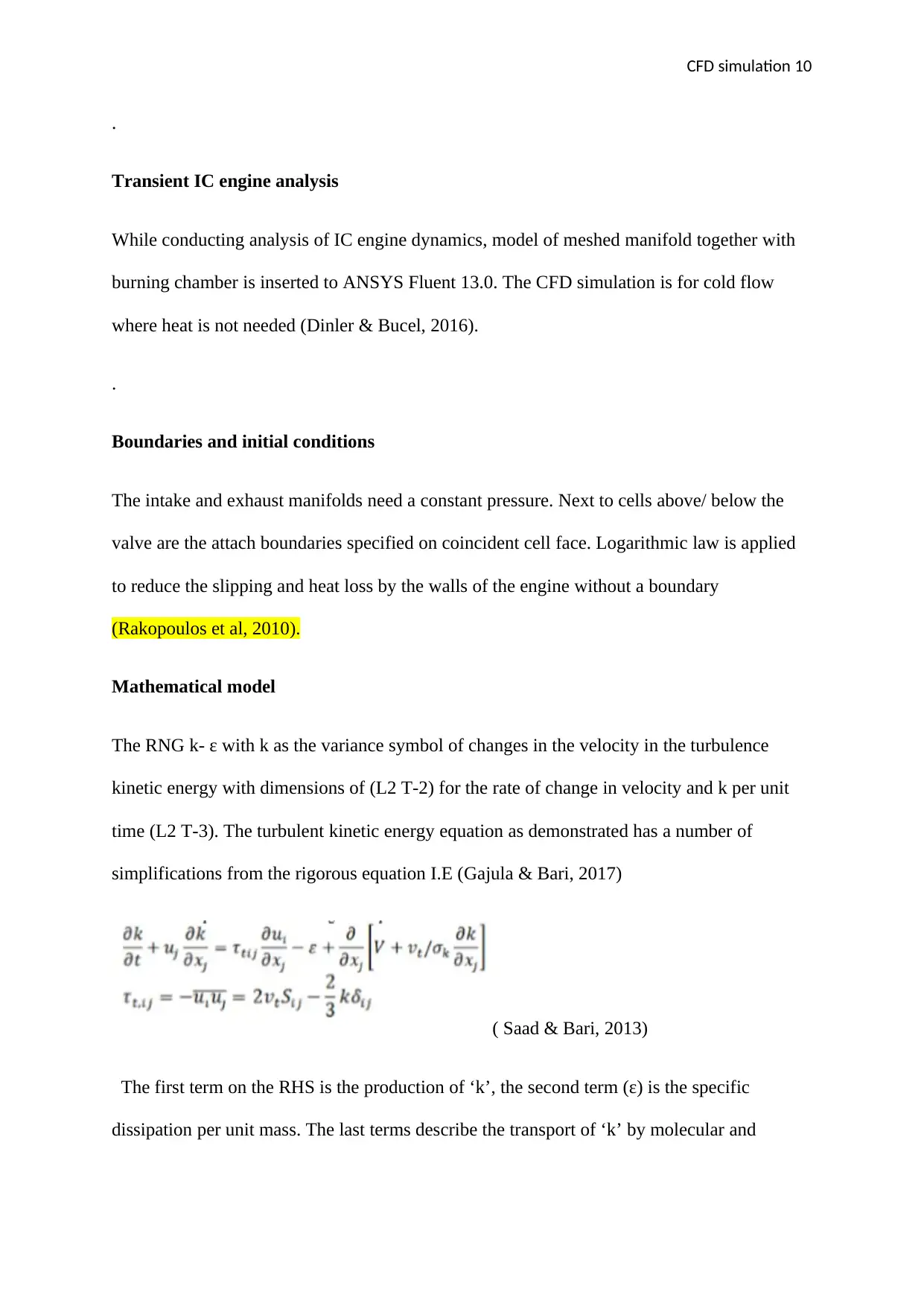
The RNG k- ε with k as the variance symbol of changes in the velocity in the turbulence
kinetic energy with dimensions of (L2 T-2) for the rate of change in velocity and k per unit
time (L2 T-3). The turbulent kinetic energy equation as demonstrated has a number of
simplifications from the rigorous equation I.E (Gajula & Bari, 2017)
( Saad & Bari, 2013)
The first term on the RHS is the production of ‘k’, the second term (ɛ) is the specific
dissipation per unit mass. The last terms describe the transport of ‘k’ by molecular and
.
Transient IC engine analysis
While conducting analysis of IC engine dynamics, model of meshed manifold together with
burning chamber is inserted to ANSYS Fluent 13.0. The CFD simulation is for cold flow
where heat is not needed (Dinler & Bucel, 2016).
.
Boundaries and initial conditions
The intake and exhaust manifolds need a constant pressure. Next to cells above/ below the
valve are the attach boundaries specified on coincident cell face. Logarithmic law is applied
to reduce the slipping and heat loss by the walls of the engine without a boundary
(Rakopoulos et al, 2010).
Mathematical model
The RNG k- ε with k as the variance symbol of changes in the velocity in the turbulence
kinetic energy with dimensions of (L2 T-2) for the rate of change in velocity and k per unit
time (L2 T-3). The turbulent kinetic energy equation as demonstrated has a number of
simplifications from the rigorous equation I.E (Gajula & Bari, 2017)
( Saad & Bari, 2013)
The first term on the RHS is the production of ‘k’, the second term (ɛ) is the specific
dissipation per unit mass. The last terms describe the transport of ‘k’ by molecular and
Paraphrase This Document
Need a fresh take? Get an instant paraphrase of this document with our AI Paraphraser
CFD simulation 11
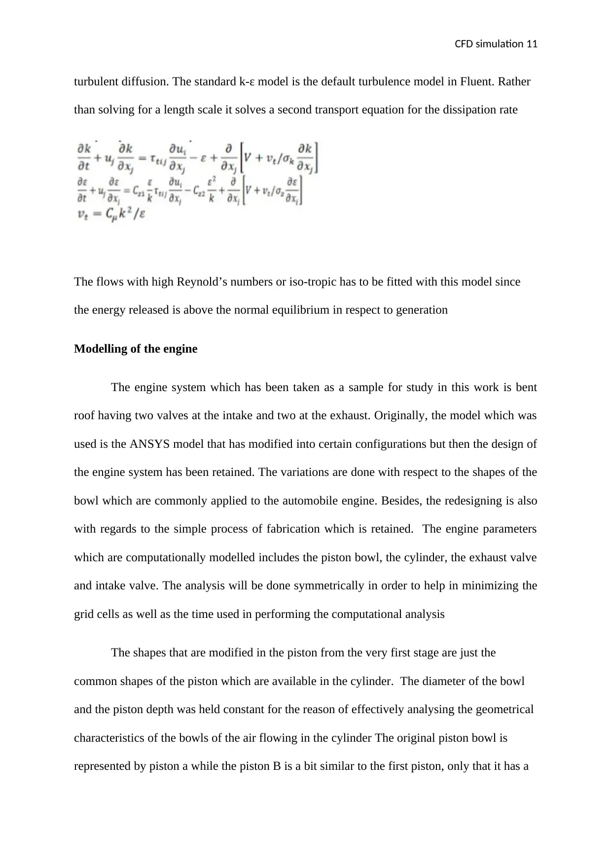
turbulent diffusion. The standard k-ɛ model is the default turbulence model in Fluent. Rather
than solving for a length scale it solves a second transport equation for the dissipation rate
The flows with high Reynold’s numbers or iso-tropic has to be fitted with this model since
the energy released is above the normal equilibrium in respect to generation
Modelling of the engine
The engine system which has been taken as a sample for study in this work is bent
roof having two valves at the intake and two at the exhaust. Originally, the model which was
used is the ANSYS model that has modified into certain configurations but then the design of
the engine system has been retained. The variations are done with respect to the shapes of the
bowl which are commonly applied to the automobile engine. Besides, the redesigning is also
with regards to the simple process of fabrication which is retained. The engine parameters
which are computationally modelled includes the piston bowl, the cylinder, the exhaust valve
and intake valve. The analysis will be done symmetrically in order to help in minimizing the
grid cells as well as the time used in performing the computational analysis
The shapes that are modified in the piston from the very first stage are just the
common shapes of the piston which are available in the cylinder. The diameter of the bowl
and the piston depth was held constant for the reason of effectively analysing the geometrical
characteristics of the bowls of the air flowing in the cylinder The original piston bowl is
represented by piston a while the piston B is a bit similar to the first piston, only that it has a
CFD simulation 12
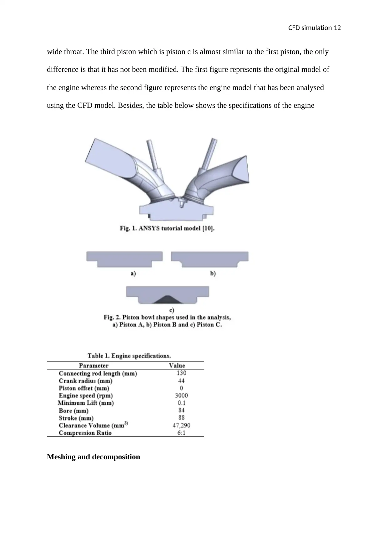
wide throat. The third piston which is piston c is almost similar to the first piston, the only
difference is that it has not been modified. The first figure represents the original model of
the engine whereas the second figure represents the engine model that has been analysed
using the CFD model. Besides, the table below shows the specifications of the engine
Meshing and decomposition
⊘ This is a preview!⊘
Do you want full access?
Subscribe today to unlock all pages.
Trusted by 1+ million students worldwide
1 out of 19
Related Documents


Your All-in-One AI-Powered Toolkit for Academic Success.
+13062052269
info@desklib.com
Available 24*7 on WhatsApp / Email
![[object Object]](/_next/static/media/star-bottom.7253800d.svg)
Unlock your academic potential
Copyright © 2020–2026 A2Z Services. All Rights Reserved. Developed and managed by ZUCOL.