Heat Transfer Analysis of Fin Cooling Systems using CFD Techniques

Verified

Added on  2023/04/03

|21
|2757
|52
Project
AI Summary
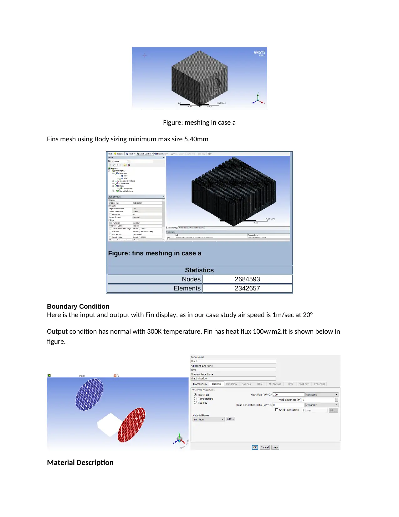
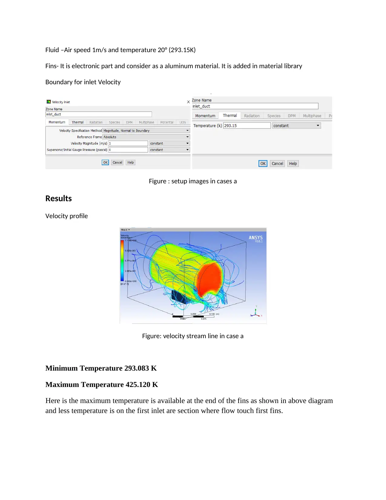
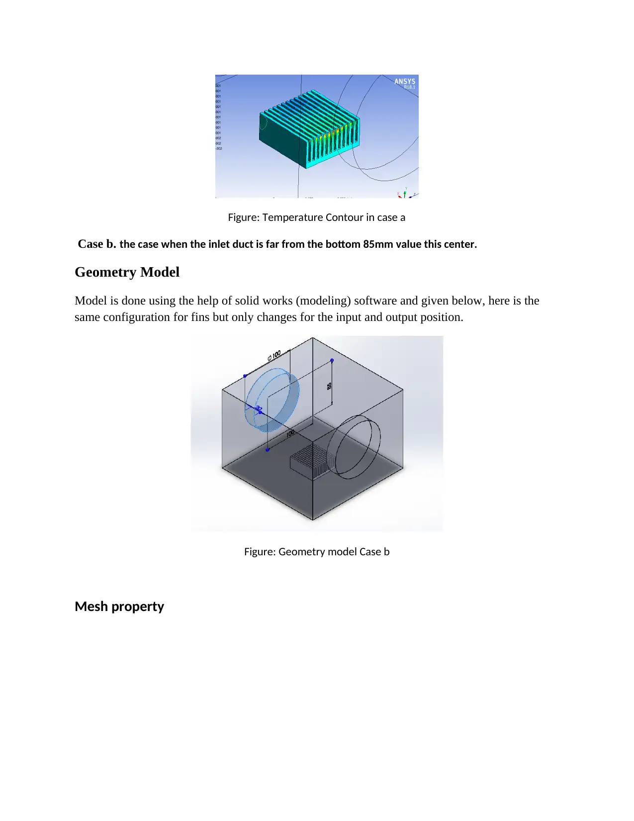
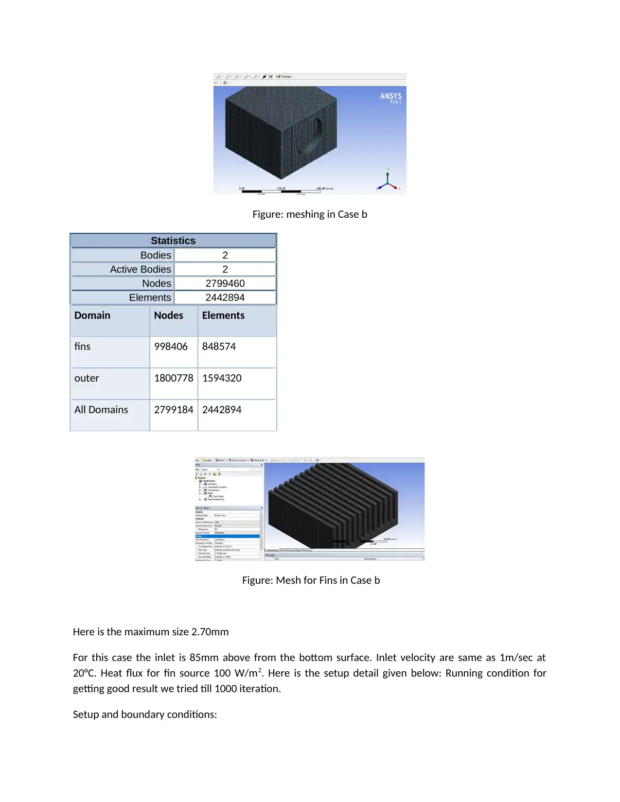
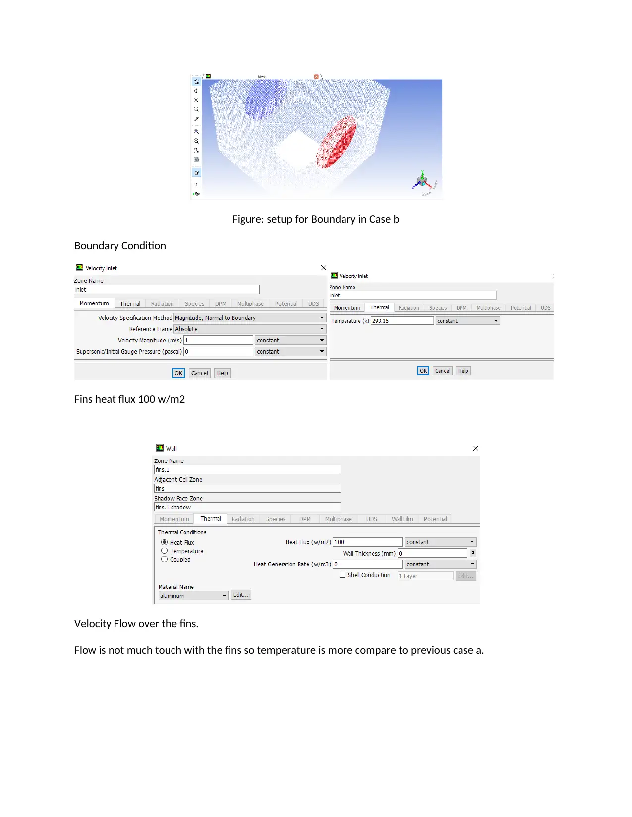
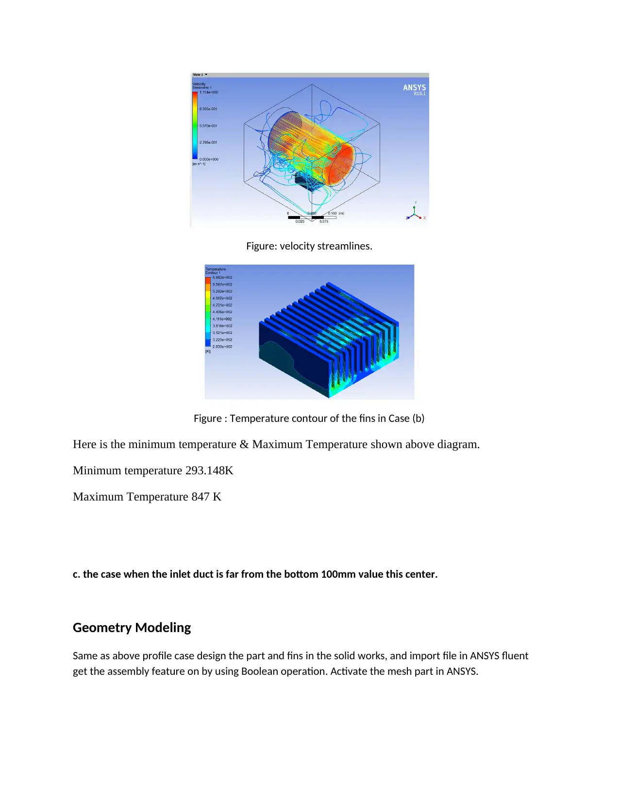
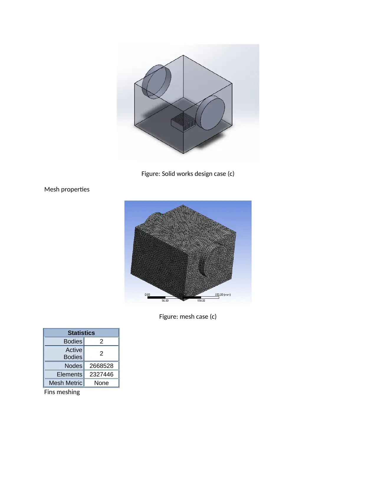
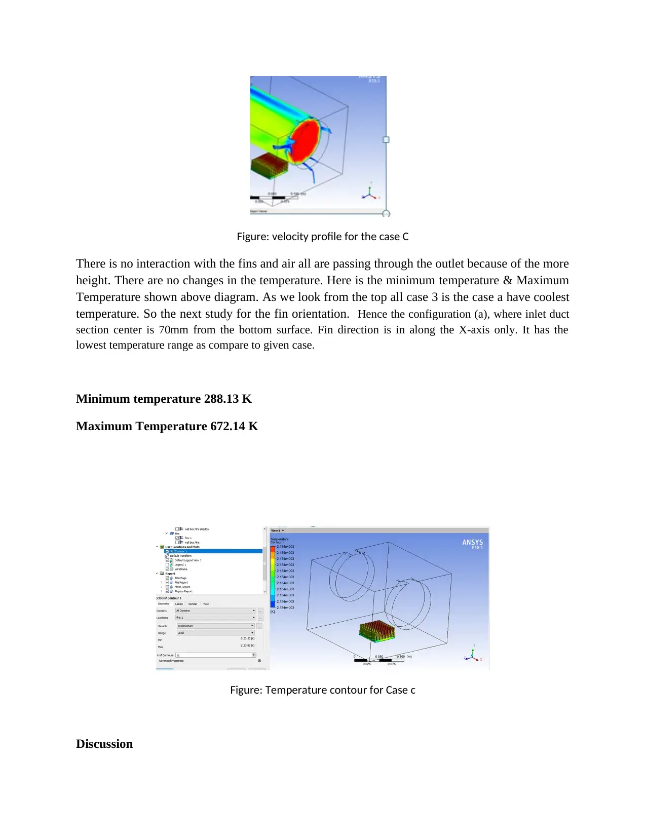
This project investigates the optimal configuration of fins for heat dissipation using Computational Fluid Dynamics (CFD) simulations within the ANSYS Fluent environment. The study examines a case study involving a fin source emitting a heat flux of 100 W/m², located within a box with inlet and outlet ducts. The analysis explores three different inlet/outlet duct positions, varying the distance from the bottom of the box. The simulations determine the minimum temperature configuration among these variations. Subsequently, the project analyzes the impact of fin orientation, comparing longitudinal and transverse arrangements relative to the airflow. The report details the modeling, meshing, boundary conditions, and results, including velocity profiles and temperature contours. The results show that the inlet duct position significantly affects temperature distribution, with the configuration where the inlet duct is closest to the bottom yielding the lowest temperatures. The study concludes that the fin's orientation also plays a crucial role in cooling efficiency. The report highlights the importance of optimizing fin design for effective heat transfer in electronic devices.
Document Page
1. Introduction
Case study regarding the CFD, where heat transfer from the fin and study about the surrounding
boundary condition.
Here we are going to the case study, where we will see the minimum temperature configuration; case is
like we have one Fins source that produce the heat flux 100w/m2. This fin is located in box. Box has two
side called inlet & outlet. From inlet cooling air flow the value 1m/s at 20°C. all type cases are given
below in the shown figure. Here are the three steps or configuration for the inlet & outlet location.
a. The centers of the inlet and outlet ducts are 70 mm above the bottom.
b. The centers of the inlet and outlet ducts are 85 mm above the bottom.
c. The centers of the inlet and outlet ducts are 100 mm above the bottom.
In the above check the minimum temperature configuration, later do the case for the fins orientation.
Where keep first fins longitudinal. And in second case keep the fins transverse from the inlet duct.
There is the basic heat transfer terminologies used in the following condition:
It is the process where heat transfer from the one body to another body. Energy transfers are due to the
temperature difference. There are the three mode of energy transfer. It is given below:
Conduction, Convection & Radiation
Conduction: The heat flow mode over the solid is called conduction. Example: flow over the tube.
Convection; energy flow in the fluid mode example: boiling water, where boil water molecule comes up
and less energy molecule goes by this process full water get boil in a pot. It is called Convection.
Radiation, Heat flow with the mode of electromagnetic waves, for example: radio waves and flame etc.
This report as we are going to discuss that belongs to cooling of the fins by using less temperature air
flow and there are basic configuration given to check out the best part of cooling affected on Fins. Here
we will study which case detail and configuration will be best for making less temperature on the fin. Fin
also producing energy and in the form of heat flux data is available.
There are the mathematical used behind the ANSYS. For transfer of heat as
Newton’s cooling law states that “the rate of heat loss by a body is directly proportional to the
temperature difference between the convective body and the surrounding”
Q= h A (Ts – T0),
Where Ts = surface temperature
T0 = Fluid temperature
tabler-icon-diamond-filled.svg

Paraphrase This Document

Need a fresh take? Get an instant paraphrase of this document with our AI Paraphraser
Document Page
h = heat convection coefficient = constant value (Nag, 2009)
A = contact surface area
Case (a) the case when the inlet duct is far from the bottom 70mm value this center.
Modeling Geometry
Model is done using the help of solid works (model) software and given below. And solution did with the
use of ANSYS software. In Ansys here we are using fluent workbench. So it is very easy to track the issue.
Figure: geometry model in case a
After finish the model is in Solid works software. We will open ANSYS where we can implement the exist
model for the setup and preprocessing work. ANSYS uses governing equation, conversation of mass,
momentum, and many more related to the heat and fluid flow.
ANSYS is divided the case into three parts Geometry, Preprocessor & Post processor.
Mesh Property
Next operation is Mesh properties- it is good to getting accuracy for the result here I have given the
sizing and refinement such type. By which we got the best result. Mesh properties are given below. To
use Meshing tool, same double click and activate the mesh. For mesh it need for refinement and several
processes are available to dot the mesh, mesh is nothing just to divide the big part into small cell. So
solver will treat every cell as a single part and result accuracy will be more. For better result meshing
need more quality.
Document Page
Figure: meshing in case a
Fins mesh using Body sizing minimum max size 5.40mm
Figure: fins meshing in case a
Statistics
Nodes 2684593
Elements 2342657
Boundary Condition
Here is the input and output with Fin display, as in our case study air speed is 1m/sec at 20°
Output condition has normal with 300K temperature. Fin has heat flux 100w/m2.it is shown below in
figure.
Material Description
Document Page
Fluid –Air speed 1m/s and temperature 20° (293.15K)
Fins- It is electronic part and consider as a aluminum material. It is added in material library
Boundary for inlet Velocity
Figure : setup images in cases a
Results
Velocity profile
Figure: velocity stream line in case a
Minimum Temperature 293.083 K
Maximum Temperature 425.120 K
Here is the maximum temperature is available at the end of the fins as shown in above diagram
and less temperature is on the first inlet are section where flow touch first fins.
tabler-icon-diamond-filled.svg

Paraphrase This Document

Need a fresh take? Get an instant paraphrase of this document with our AI Paraphraser
Document Page
Figure: Temperature Contour in case a
Case b. the case when the inlet duct is far from the bottom 85mm value this center.
Geometry Model
Model is done using the help of solid works (modeling) software and given below, here is the
same configuration for fins but only changes for the input and output position.
Figure: Geometry model Case b
Mesh property
Document Page
Figure: meshing in Case b
Statistics
Bodies 2
Active Bodies 2
Nodes 2799460
Elements 2442894
Domain Nodes Elements
fins 998406 848574
outer 1800778 1594320
All Domains 2799184 2442894
Figure: Mesh for Fins in Case b
Here is the maximum size 2.70mm
For this case the inlet is 85mm above from the bottom surface. Inlet velocity are same as 1m/sec at
20°C. Heat flux for fin source 100 W/m2. Here is the setup detail given below: Running condition for
getting good result we tried till 1000 iteration.
Setup and boundary conditions:
Document Page
Figure: setup for Boundary in Case b
Boundary Condition
Fins heat flux 100 w/m2
Velocity Flow over the fins.
Flow is not much touch with the fins so temperature is more compare to previous case a.
tabler-icon-diamond-filled.svg

Paraphrase This Document

Need a fresh take? Get an instant paraphrase of this document with our AI Paraphraser
Document Page
Figure: velocity streamlines.
Figure : Temperature contour of the fins in Case (b)
Here is the minimum temperature & Maximum Temperature shown above diagram.
Minimum temperature 293.148K
Maximum Temperature 847 K
c. the case when the inlet duct is far from the bottom 100mm value this center.
Geometry Modeling
Same as above profile case design the part and fins in the solid works, and import file in ANSYS fluent
get the assembly feature on by using Boolean operation. Activate the mesh part in ANSYS.
Document Page
Figure: Solid works design case (c)
Mesh properties
Figure: mesh case (c)
Statistics
Bodies 2
Active
Bodies 2
Nodes 2668528
Elements 2327446
Mesh Metric None
Fins meshing
Document Page
Figure: Mesh properties for the fin case C
Setup and Boundary details:
Due to the inlet height is equal to the box height, For this configuration, the inlet is 100mm from the
bottom and set the air speed 1m/s with 20° C.
Fins are same location as and have heat flux 100 w/m2.
Boundary Condition for the fins
Inlet velocity
Figure: inlet setup velocity
Velocity profile
tabler-icon-diamond-filled.svg

Paraphrase This Document

Need a fresh take? Get an instant paraphrase of this document with our AI Paraphraser
Document Page
Figure: velocity profile for the case C
There is no interaction with the fins and air all are passing through the outlet because of the more
height. There are no changes in the temperature. Here is the minimum temperature & Maximum
Temperature shown above diagram. As we look from the top all case 3 is the case a have coolest
temperature. So the next study for the fin orientation. Hence the configuration (a), where inlet duct
section center is 70mm from the bottom surface. Fin direction is in along the X-axis only. It has the
lowest temperature range as compare to given case.
Minimum temperature 288.13 K
Maximum Temperature 672.14 K
Figure: Temperature contour for Case c
Discussion
Document Page
We study the all three process where we got too much temperature difference by relocating the
inlet & outlet section for the duct. In the first case we found that it has least temperature as
compare the other two cases. It has temperature max is 425K and temperature min is 293K.
Configuration Temperature Min(K) Temperature Max (K)
a 293 425
b 293 847
c 288 672
For the second case b, we got the Maximum temperature 847K and minimum temperature 293K.
There are hike in temperature due to height of the inlet from the bottom surface.
Third case is the moderate temperature value 288K & maximum temperature 672K.
Final conclusion is that case a where inlet section is on 70 mm from the bottom, it has less
temperature. So we are taking this as a less configuration. And so we have new case study to
fixed the inlet location and change the orientations of the Fins. In such we will try to check
which has min temperature over the fin.
Case 1: Fins are align, parallel and along the X- direction.
Case 2: Fins are perpendicular to Floe and towards Y direction. we are doing now reorientation
of the fin towards Y- direction, here is the report below:
a. The fins are longitudinal to the x-direction.
Here is the configuration, here we have done previously case a where the inlet section is 70 mm
from the bottom area.
Case (X)
Modeling Geometry
Model is used and design in Solid works software. Here are the case given as same as case (a)
the above and it’s given below as per different location of the Fan. Case (X) the centers of the
inlet & outlet ducts is 70 mm from bottom area.
chevron_up_icon
1 out of 21
circle_padding
hide_on_mobile
zoom_out_icon
[object Object]