CFD Analysis Report: Aerodynamic Simulation of VAN and Trailer

Verified

Added on  2023/01/17

|28
|2834
|90
Practical Assignment
AI Summary
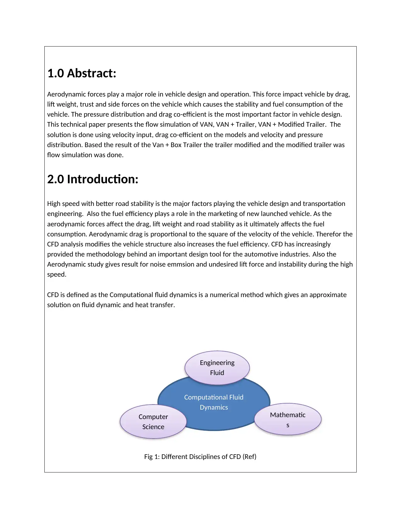
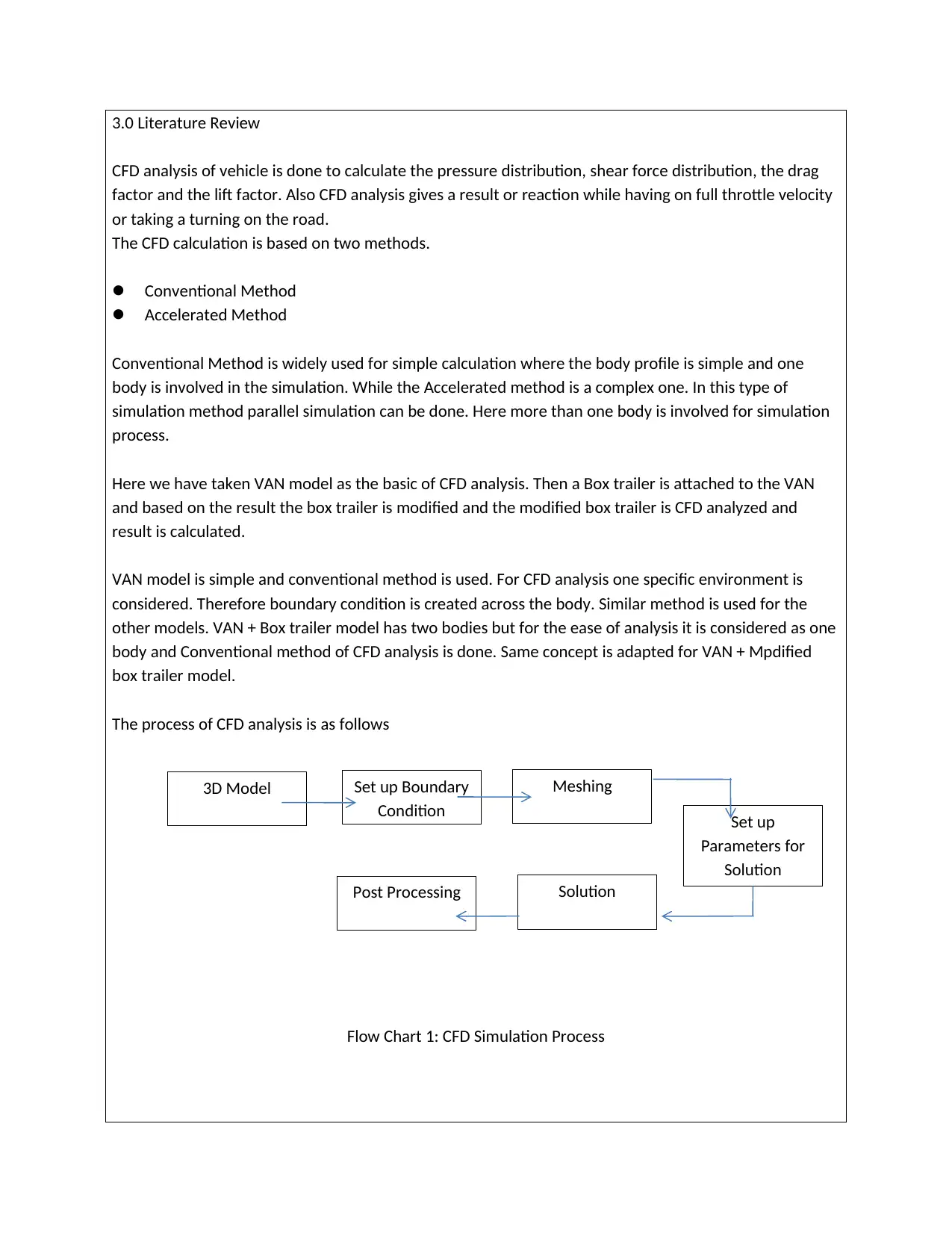
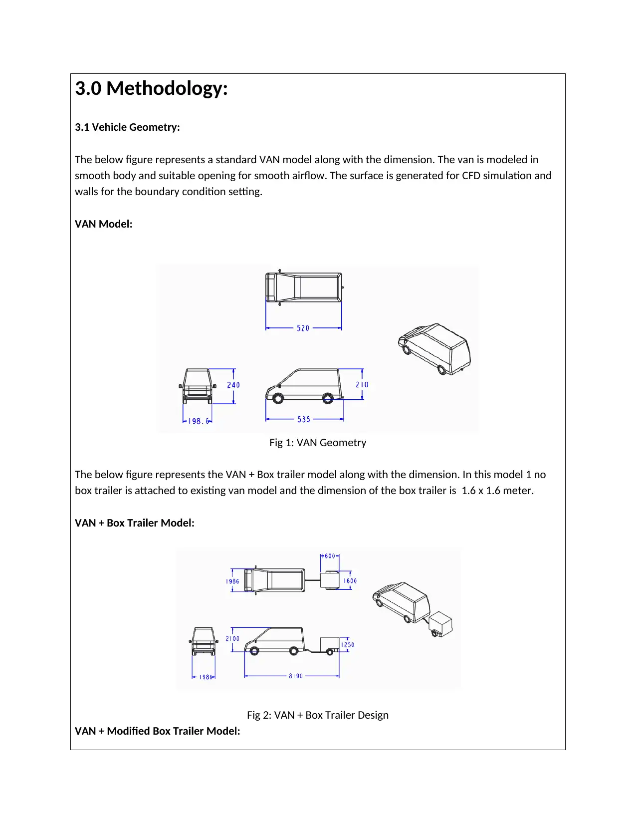
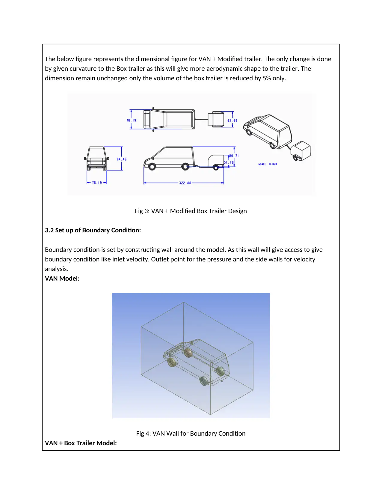
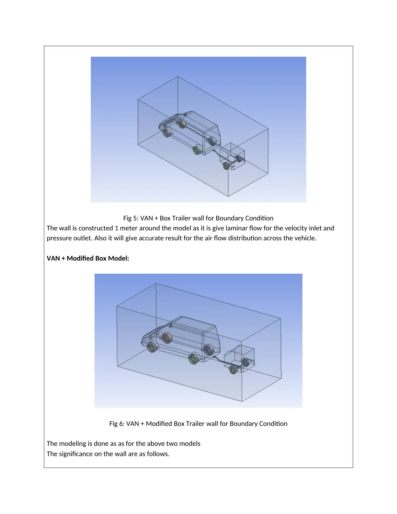
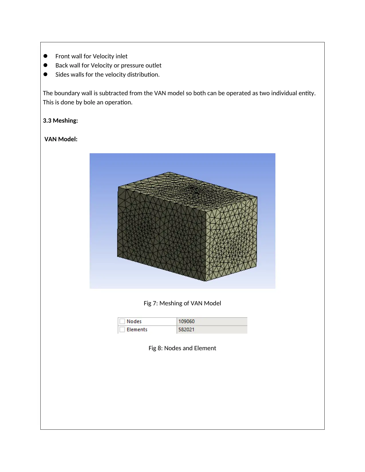
This assignment presents a comprehensive computational fluid dynamics (CFD) analysis of VAN and trailer aerodynamics. The study investigates the impact of aerodynamic forces, such as drag and lift, on vehicle performance and fuel consumption. The methodology involves creating 3D models of a standard VAN, a VAN with a box trailer, and a VAN with a modified box trailer, followed by setting up boundary conditions, meshing the models, and performing flow simulations. The results include pressure distribution, velocity streamlines, and drag coefficients, which are then analyzed to evaluate the aerodynamic characteristics of each configuration. The report includes detailed explanations of the methodology, results, and conclusions, providing insights into the effectiveness of trailer modifications in improving aerodynamic efficiency.
Document Page
CFD Analysis of VAN and Trailer
tabler-icon-diamond-filled.svg

Paraphrase This Document

Need a fresh take? Get an instant paraphrase of this document with our AI Paraphraser
Document Page
Table of Content:
1.0 Abstract 3
2.0 Introduction 3
3.0 Methodology
3.1 Vehicle Geometry 4
3.2 Set up of Boundary Condition 5
3.3 Meshing 7
3.4 Solution Set up 11
3.5 Boundary Condition 11
3.6 Solver Set up 12
4.0 Result and Post Processing 15
4.1 Iteration Process 16
4.2 Pressure Distribution 19
4.3 Velocity Streamline 22
5.0 Conclusion 23
List of Figure 25
List of Table 26
Reference 27
Document Page
1.0 Abstract:
Aerodynamic forces play a major role in vehicle design and operation. This force impact vehicle by drag,
lift weight, trust and side forces on the vehicle which causes the stability and fuel consumption of the
vehicle. The pressure distribution and drag co-efficient is the most important factor in vehicle design.
This technical paper presents the flow simulation of VAN, VAN + Trailer, VAN + Modified Trailer. The
solution is done using velocity input, drag co-efficient on the models and velocity and pressure
distribution. Based the result of the Van + Box Trailer the trailer modified and the modified trailer was
flow simulation was done.
2.0 Introduction:
High speed with better road stability is the major factors playing the vehicle design and transportation
engineering. Also the fuel efficiency plays a role in the marketing of new launched vehicle. As the
aerodynamic forces affect the drag, lift weight and road stability as it ultimately affects the fuel
consumption. Aerodynamic drag is proportional to the square of the velocity of the vehicle. Therefor the
CFD analysis modifies the vehicle structure also increases the fuel efficiency. CFD has increasingly
provided the methodology behind an important design tool for the automotive industries. Also the
Aerodynamic study gives result for noise emmsion and undesired lift force and instability during the high
speed.
CFD is defined as the Computational fluid dynamics is a numerical method which gives an approximate
solution on fluid dynamic and heat transfer.
Fig 1: Different Disciplines of CFD (Ref)
Computational Fluid
Dynamics
Engineering
Fluid
Dynamics
Mathematic
s
Computer
Science
Document Page
3.0 Literature Review
CFD analysis of vehicle is done to calculate the pressure distribution, shear force distribution, the drag
factor and the lift factor. Also CFD analysis gives a result or reaction while having on full throttle velocity
or taking a turning on the road.
The CFD calculation is based on two methods.
Conventional Method
Accelerated Method
Conventional Method is widely used for simple calculation where the body profile is simple and one
body is involved in the simulation. While the Accelerated method is a complex one. In this type of
simulation method parallel simulation can be done. Here more than one body is involved for simulation
process.
Here we have taken VAN model as the basic of CFD analysis. Then a Box trailer is attached to the VAN
and based on the result the box trailer is modified and the modified box trailer is CFD analyzed and
result is calculated.
VAN model is simple and conventional method is used. For CFD analysis one specific environment is
considered. Therefore boundary condition is created across the body. Similar method is used for the
other models. VAN + Box trailer model has two bodies but for the ease of analysis it is considered as one
body and Conventional method of CFD analysis is done. Same concept is adapted for VAN + Mpdified
box trailer model.
The process of CFD analysis is as follows
Flow Chart 1: CFD Simulation Process
3D Model Set up Boundary
Condition
Meshing
Set up
Parameters for
Solution
SolutionPost Processing
tabler-icon-diamond-filled.svg

Paraphrase This Document

Need a fresh take? Get an instant paraphrase of this document with our AI Paraphraser
Document Page
3.0 Methodology:
3.1 Vehicle Geometry:
The below figure represents a standard VAN model along with the dimension. The van is modeled in
smooth body and suitable opening for smooth airflow. The surface is generated for CFD simulation and
walls for the boundary condition setting.
VAN Model:
Fig 1: VAN Geometry
The below figure represents the VAN + Box trailer model along with the dimension. In this model 1 no
box trailer is attached to existing van model and the dimension of the box trailer is 1.6 x 1.6 meter.
VAN + Box Trailer Model:
Fig 2: VAN + Box Trailer Design
VAN + Modified Box Trailer Model:
Document Page
The below figure represents the dimensional figure for VAN + Modified trailer. The only change is done
by given curvature to the Box trailer as this will give more aerodynamic shape to the trailer. The
dimension remain unchanged only the volume of the box trailer is reduced by 5% only.
Fig 3: VAN + Modified Box Trailer Design
3.2 Set up of Boundary Condition:
Boundary condition is set by constructing wall around the model. As this wall will give access to give
boundary condition like inlet velocity, Outlet point for the pressure and the side walls for velocity
analysis.
VAN Model:
Fig 4: VAN Wall for Boundary Condition
VAN + Box Trailer Model:
Document Page
Fig 5: VAN + Box Trailer wall for Boundary Condition
The wall is constructed 1 meter around the model as it is give laminar flow for the velocity inlet and
pressure outlet. Also it will give accurate result for the air flow distribution across the vehicle.
VAN + Modified Box Model:
Fig 6: VAN + Modified Box Trailer wall for Boundary Condition
The modeling is done as as for the above two models
The significance on the wall are as follows.
tabler-icon-diamond-filled.svg

Paraphrase This Document

Need a fresh take? Get an instant paraphrase of this document with our AI Paraphraser
Document Page
Front wall for Velocity inlet
Back wall for Velocity or pressure outlet
Sides walls for the velocity distribution.
The boundary wall is subtracted from the VAN model so both can be operated as two individual entity.
This is done by bole an operation.
3.3 Meshing:
VAN Model:
Fig 7: Meshing of VAN Model
Fig 8: Nodes and Element
Document Page
Fig 9: Element Quality
Tetraheadral meshing is selected for this model and the total element is 582021, which is quite good for
this CFD analysis. The mesh quality is around 0.9 which is considered to be best. The low mesh quality is
around the mirror region as it has lots of curvature so element size which is 50 mm is not properly
covering the curvature. But considering this high quality mesh we can proceed further for the analysis
part.
Also the Mesh quality is checked for different values as per the below table
Model No of Element No of Nodes Element Quality
Case 1 425863 88536 0.66
Case 2 582021 109060 0.9
Case 3 725865 196532 0.75
Table 1: Test Condition for Mesh Quality VAN Model
VAN + Box Trailer Model:
Fig 10: Meshing of VAN + Box Trailer Model
Document Page
Fig 11: Nodes and Elements
Fig 12: Element Quality
Considering above data generated from the meshing the VAN + Box trailer model the number of
elements is 896679 and the mesh quality is upto 0.88. The element size is defined as 50 mm. Here also
the low mesh quality is for mirror reason and the reason is same. This data is good enough to proceed
further for the solution type.
Model No of Element No of Nodes Element Quality
Case 1 625845 125036 0.73
Case 2 896679 168582 0.88
Case 3 1258452 325689 0.63
Table 2: Test Condition for Mesh Quality VAN + Box Trailer Model
tabler-icon-diamond-filled.svg

Paraphrase This Document

Need a fresh take? Get an instant paraphrase of this document with our AI Paraphraser
Document Page
VAN + Modified Box Trailer Model
Fig 13: Meshing of VAN + Modified CAD Model
Fig 14: Nodes and Elements
Fig 15: Element Quality
Considering above data generated from the meshing the VAN + Box trailer model the number of
elements is 899748 and the mesh quality is upto 0.88. The element size is defined as 50 mm. Here also
the low mesh quality is for mirror reason and the reason is same. This data is good enough to proceed
further for the solution type.
Model No of Element No of Nodes Element Quality
Document Page
Case 1 648578 125036 0.69
Case 2 899748 169143 0.88
Case 3 1285425 385268 0.58
Table 3: Test Condition for Mesh Quality VAN + Modified Box Trailer Model
3.4 Solution Set up:
Solution set up is the parameter setting and setting the boundary condition for the model. In the present
study all the computation is done using three dimensional RANS model with an industry standard finite
volume based CFD codes. The set of equation solved are UN-steady condition, therefore we are using
double precision method for boundary condition set up and solution.
Navier equation in their conservation form for turbulent flow and averaging the steady, turbulent and in
compressible flow.
The governing equation for this is based on equation of continuity.
The Turbulance modeling is based on standard k-Ɛ model is used for the simulation. This condition is not
well defined near the wall. As this a relation velocity and the surface shear stress.
3.5 Boundary Condition:
The boundary condition is as follows:
Faces Boundary Condition
Front Face Inflow
Rear Face Inflow
chevron_up_icon
1 out of 28
circle_padding
hide_on_mobile
zoom_out_icon
[object Object]