CG4007 Sustainable Energy Processes: Steam System Heat Balance
VerifiedAdded on 2023/05/29
|20
|2097
|311
Report
AI Summary
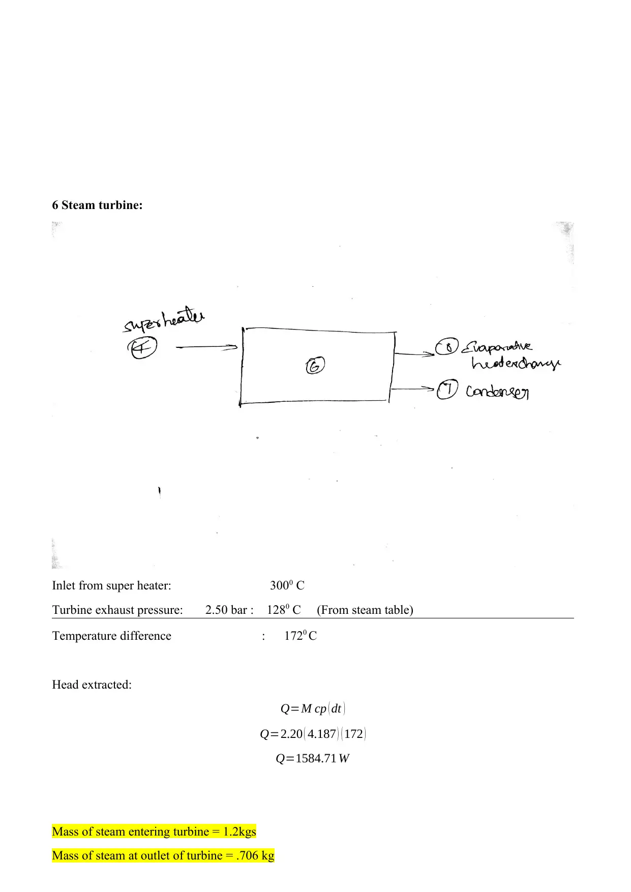
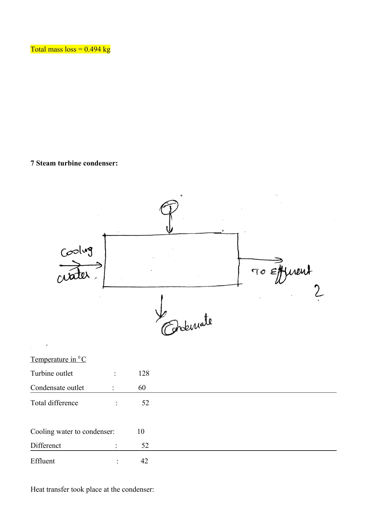
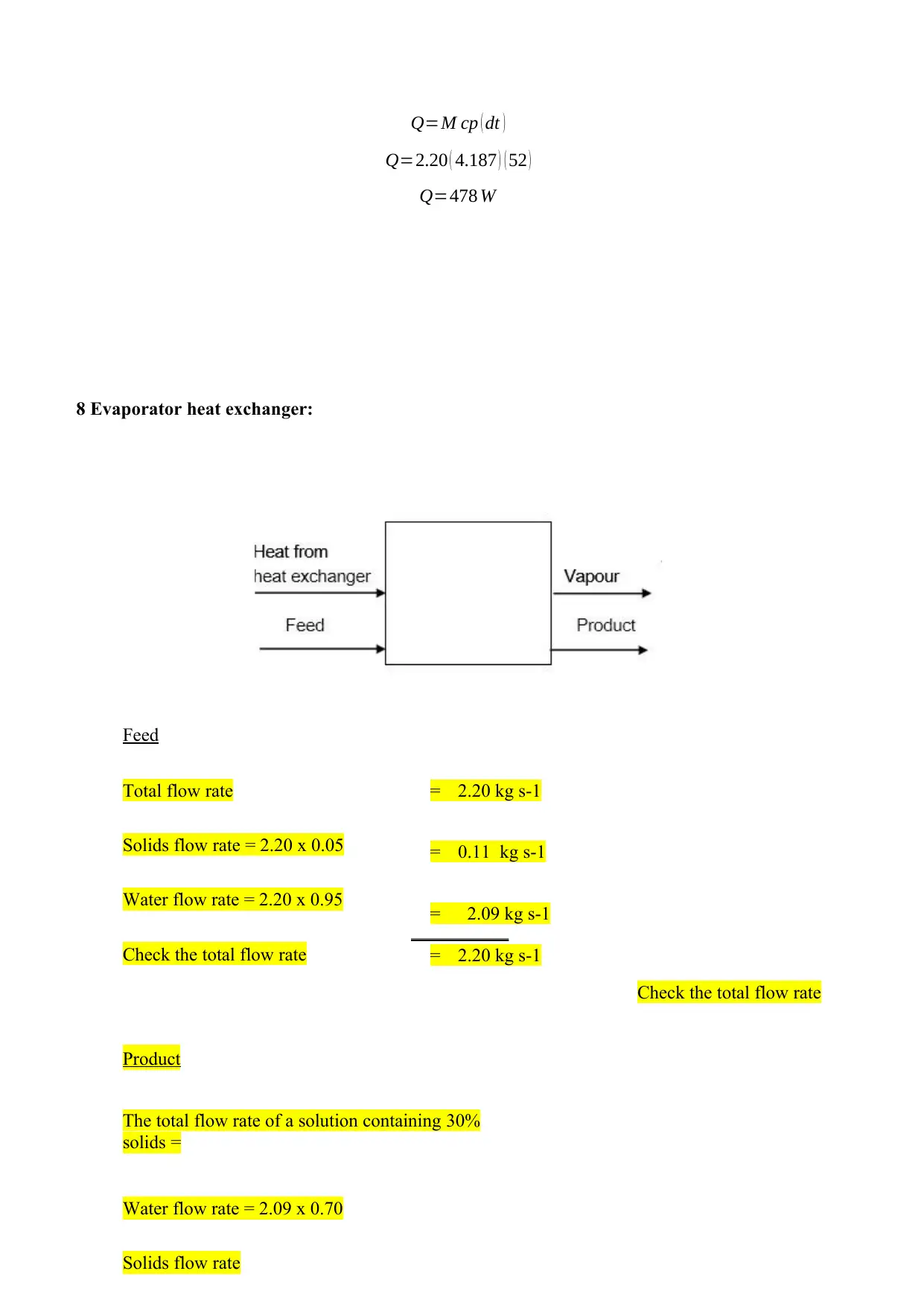
This report provides a comprehensive description and analysis of a steam turbine power plant system, focusing on its application within a production unit utilizing a steam turbine for electricity generation and a forced circulation evaporator for product creation. It includes a detailed heat and mass balance for one product, calculated to four significant figures, along with an evaluation of the thermal efficiency of the boiler and superheater. The report also assesses the overall thermal efficiency of the system and offers suggestions for potential improvements, referencing data obtained from steady-state test runs conducted on the system. The analysis covers key components such as the deionizer unit, boiler water feed tank, boiler, superheater, steam turbine, condenser, evaporator, and associated condensers and vessels, providing a holistic view of the steam system's operation and performance.
Contribute Materials
Your contribution can guide someone’s learning journey. Share your
documents today.

Steam Design Project
Secure Best Marks with AI Grader
Need help grading? Try our AI Grader for instant feedback on your assignments.

System Description:
A steam Turbine power plant is the system which is used for generating electrical energy from the
input heat energy. The gas turbines Power plants consist of four main circuits they are Ash and Coal
handling section, the Cooling water circuit, Air and Gas circuit and feed water and steam circuit’.1
The layout of a general steam power plant system is shown below:
Fig1. Shows layout of a modern power plant
Coal and ash handling system:
The coal and ash Handling system deals with the handling of coal which arrives at the storage yard,
conditioning it, using it for the purpose of heat generation to provide heat input to the boiler and then
removing and storing the Ash generated due to the burning of the coal.
Air and Gas circuit:
The atmospheric air is taken through a draught system it may be forced, induced or balanced. The air
is filtered and the dust is removed and then it is supplied to the combustion chamber. The air is
allowed to pass through an air pre-heater before feeding it for the combustion. The air preheater
utilizes the hot flue gases for the purpose of heating the incoming air.
1 M.S. Murshitha Shajahan, D. Najumnissa Jamal, V. Aparna and M.K.A. Ahamed Khan, ‘Control of
electric power generation of thermal power plant in TamilNadu’, Case Studies in Thermal
Engineering, Vol. 12, 2018, pp. 728-735.

The air after completing the combustion becomes hot flue gas. The flue gas contains heat and some
quantity of ash. The flue gas is initially allowed to pass through the air preheater to exchange heat
with the inlet fresh air. Then the flue gas is passed through dust collectors in which most of the ash
and dust content of the flue air is removed. Then the flue air is allowed to exhaust to the atmosphere
via the chimney’.2
Feed water and Steam circuit:
The water follows a closed loop in this system. The condensed water from the condenser is allowed to
the boiler via economizer. The economizer uses the flue gases to preheat the feed water. The feed
water is then heated at the boiler the water is converted into steam. The generated steam is then
allowed to pass through the superheating boiler where the steam will be super-heated. Then the steam
is expanded in the Steam turbine. The expanded steam will have low velocity and low enthalpy. Then
the expanded steam is condensed in the condenser. There is always some form of water loss from the
circuit throughout the cycle so some fresh water is allowed inside the feed water pump to compensate
the loss’.2
Cooling water circuit:
The cooling water circuit consists of the water that is required to cool the steam flowing through the
condenser. The Water source is taken from large reservoirs such as lake, sea and rivers. The cooling
water may have an open loop circuit or closed loop circuit. In an open loop circuit the water taken
from the reservoir is allowed to flow out to the surrounding. In the case of a closed-loop system same
water is being circulated again and again inside the condenser the open loop system needs a separate
water cooling system such as an evaporative cooler’.4
General working:
The steam which is generated from the boiler is allowed to expand through the steam turbine which
in turn rotates the alternator. The conversion of the Mechanical energy into electrical energy is
achieved with the help of alternator. The steam turbine converts the steam energy into mechanical
energy. The steam-powered turbine works on the principle of baryon cycle.
2 M. K. Gupta and S. C. Kaushik, "Exergetic utilization of solar energy for feed water preheating in a
conventional thermal power plant", International Journal of Energy Research, Vol. 33, no. 6, 2009,
pp. 593-604.
4 A.N. Anozie and O.J. Odejobi, "The search for optimum condenser cooling water flow rate in a
thermal power plant", Applied Thermal Engineering, Vol. 31, no. 17-18, 2011, pp. 4083-4090.

Heat and mass balance:
1. Deionizer unit
Feed:
Feed water to 1 temperature: 15 degree Celsius
Feed temp to evaporative surface (10) condenser: 15 0 C
The temperature of the De super heater: 15 0 C
Inlet Condition : 15 0 C
Exit Conditions at 10: 150 C
Heat balance: 00 C
12 12
10
2
Feed water 1
1. Deionizer unit
Feed:
Feed water to 1 temperature: 15 degree Celsius
Feed temp to evaporative surface (10) condenser: 15 0 C
The temperature of the De super heater: 15 0 C
Inlet Condition : 15 0 C
Exit Conditions at 10: 150 C
Heat balance: 00 C
12 12
10
2
Feed water 1
Secure Best Marks with AI Grader
Need help grading? Try our AI Grader for instant feedback on your assignments.

2. Boiler water feed tank:
Temperatures:
Condensate from turbine condenser (7) : 1200 C
Water from evaporator condenser (10) : 60 0 C
Feed water to 1 temperature (1) : 15 0 C
Feed water temp to boiler:?
Heat balance:
Inlet conditions: 120
60
15
Exit condition: 650 C
The feed water temperature to the boiler is 195 degree Celsius.
7, 10
3
Feed water
1
12

3 Boiler:
Feed to boiler:
Here,
15. Boiler water feed pump
16. Boiler oil feed pump
17. Boiler F.D fan
5. Live steam distillation unit
18 Boiler I.D fan
4. Superheater.
Temperatures in 0 C:
Boiler Feed Temperature : 650 C
Boiler pressure &super heater feed : 20 bar : 2150 C (from steam table)
Temperature added at the boiler 1500 C
Heat added at the boiler:
Q=M cp ( ¿ )
Q=2.20 ( 4.187 ) ( 150 )
Q=1381 W
Mass of water in 2.20 kgs/s
Mass of the steam leaving the boiler 1.7kgs/s
Overall mass = massage of water in – Mass of steam leaving
Amount of water loss = 2.20 – 1.7
= 0.5 kgs.
Fresh Feed water to be added = 0.5kg
12
15
17
16
3 12 18
12 4
5
12

4 Superheater:
Boiler feed to superheater: 2150 C
Superheated steam Temperature: 3000 C
Air to superheater 200 C
The temperature to be added by superheater: 650 C
Heat added at the superheater:
Q=M cp ( dt )
Q=2.20 ( 4.187 ) ( 65 )
Q=598.71 W
Mass of steam inlet super heater = 1.7kgs/s
Mass of steam leaving super heater = 1.2kgs/s
Total loss = 1.7 – 1.2 = 0.5 kg/s
Paraphrase This Document
Need a fresh take? Get an instant paraphrase of this document with our AI Paraphraser

5 Live steam distillation unit:
Inlet from the boiler: 2150 C
Exit conditions: 2150 C
Heat temp added: 00 C
The distillatory distills the steam so no external or internal energy transfer took place. As the inlet and
exit conditions are similar.
53
Inlet from the boiler: 2150 C
Exit conditions: 2150 C
Heat temp added: 00 C
The distillatory distills the steam so no external or internal energy transfer took place. As the inlet and
exit conditions are similar.
53

6 Steam turbine:
Inlet from super heater: 3000 C
Turbine exhaust pressure: 2.50 bar : 1280 C (From steam table)
Temperature difference : 1720 C
Head extracted:
Q=M cp ( dt )
Q=2.20 ( 4.187 ) ( 172 )
Q=1584.71 W
Mass of steam entering turbine = 1.2kgs
Mass of steam at outlet of turbine = .706 kg
Inlet from super heater: 3000 C
Turbine exhaust pressure: 2.50 bar : 1280 C (From steam table)
Temperature difference : 1720 C
Head extracted:
Q=M cp ( dt )
Q=2.20 ( 4.187 ) ( 172 )
Q=1584.71 W
Mass of steam entering turbine = 1.2kgs
Mass of steam at outlet of turbine = .706 kg

Total mass loss = 0.494 kg
7 Steam turbine condenser:
Temperature in 0 C
Turbine outlet : 128
Condensate outlet : 60
Total difference : 52
Cooling water to condenser: 10
Differenct : 52
Effluent : 42
Heat transfer took place at the condenser:
7 Steam turbine condenser:
Temperature in 0 C
Turbine outlet : 128
Condensate outlet : 60
Total difference : 52
Cooling water to condenser: 10
Differenct : 52
Effluent : 42
Heat transfer took place at the condenser:
Secure Best Marks with AI Grader
Need help grading? Try our AI Grader for instant feedback on your assignments.

Q=M cp ( dt )
Q=2.20 ( 4.187 ) ( 52 )
Q=478 W
8 Evaporator heat exchanger:
Feed
Total flow rate
Solids flow rate = 2.20 x 0.05
Water flow rate = 2.20 x 0.95
Check the total flow rate
= 2.20 kg s-1
= 0.11 kg s-1
= 2.09 kg s-1
= 2.20 kg s-1
Product
The total flow rate of a solution containing 30%
solids =
Water flow rate = 2.09 x 0.70
Solids flow rate
Check the total flow rate

0.11
0.3
= 0.3
66
6
kg
s-1
= 1.4
63
kg
s-1
= 0.1
1
kg
s-1
= 1.5
73
kg
s-1
0.3
= 0.3
66
6
kg
s-1
= 1.4
63
kg
s-1
= 0.1
1
kg
s-1
= 1.5
73
kg
s-1

Water to be evaporated
Water in – water out = 2.20 – 1.463 = 0.737 kg s-1
Heat balance
Heat in 2.20 kg s-1 of feed at 15ºC
= 2.00 x 83.9 x 103 = 167.8 x 10³W
Heat in 1.14 kg s-1
of product at 70ºC = 0.750 x 289 x 103=216.8 x 103 = 216.8 x
103W
Heat in 1.250 kg s-
1 of dry vapour at 0.30 bar absolute =
1.250[289 + (0.97 x 2336)]103
= 3194 x
103W
Heat to be added in heat exchanger = (3194 + 216.8 – 167.8)103 = 3243 x 103
Paraphrase This Document
Need a fresh take? Get an instant paraphrase of this document with our AI Paraphraser

9 Evaporator flash vessel:
Temperature in:
Feed to flash vessel: 690 C
Super heated forced draught: 1920 C
Heat difference: 123 0 C
Evaporated air:
In – out: 2.20 – 0.5 = 1.7 kg/s
98 14
20
Temperature in:
Feed to flash vessel: 690 C
Super heated forced draught: 1920 C
Heat difference: 123 0 C
Evaporated air:
In – out: 2.20 – 0.5 = 1.7 kg/s
98 14
20

10 Evaporator surface condenser:
Temperature in 0 C
Water inlet condition : 128
Condensate outlet : 60
Total difference : 52
Cooling water to condenser: 10
Difference : 52
Effluent : 42
Heat transfer took place at the condenser:
Q=M cp ( dt )
Q=2.20 ( 4.187 ) ( 52 )
Q=478.63 W
Temperature in 0 C
Water inlet condition : 128
Condensate outlet : 60
Total difference : 52
Cooling water to condenser: 10
Difference : 52
Effluent : 42
Heat transfer took place at the condenser:
Q=M cp ( dt )
Q=2.20 ( 4.187 ) ( 52 )
Q=478.63 W

11 Evaporator jet condenser:
Temperature inlet:
Cooling water : 100C
Water outlet : 120 0 C
Balance : 110 deg C
Heat transfer took place at the condenser:
Q=M cp ( dt )
Q=1.20 ( 4.187 ) ( 110 )
Q=550 W
11Cool water 10
13 To vaccumn
Temperature inlet:
Cooling water : 100C
Water outlet : 120 0 C
Balance : 110 deg C
Heat transfer took place at the condenser:
Q=M cp ( dt )
Q=1.20 ( 4.187 ) ( 110 )
Q=550 W
11Cool water 10
13 To vaccumn
Secure Best Marks with AI Grader
Need help grading? Try our AI Grader for instant feedback on your assignments.

12 De-superheater:
De super heater reduces the temperature of the steam in order to reduce its super heating
temperature:
Heat input: From super heater bleed
Output: Cooled down
Balance : Difference
Coooling water inlet: 10 deg C
Cooling water outlet : As per heat transger
Difference: overall
Heat removed:
Q=−M C dt
121 25

Boiler efficiency:
E=[Q(H−h)/CV ]∗100
Here,
Q is the quantity of steam generated
H enthalpy of steam
h- enthalpy of water
CV calorific value of fuel
E=2.20(1620−1250)/2200
E=37 %
Super heater efficiency:
E=Qa
Qs x 100
Here,
Qs heat supplie
Qa heat added
E= 598
1580 =.38
E=38 %
The efficiency of the plant:
efficiency η= Wt
Q
Wt workdone by turbine: 750 KW
Q heat supplied: 1584 KW
η=0.47

Efficiency is found to be 47 Percentage.
The thermal efficiency could be improved by’.3 :
Proper insulation between the system and the surrounding.
Maintenance of parts
Improved steam quality
Feed water quality
Clean and neat heat energy input
Turbine periodical maintainace
Reheating
The thermal efficiency could be improved by’.3 :
Proper insulation between the system and the surrounding.
Maintenance of parts
Improved steam quality
Feed water quality
Clean and neat heat energy input
Turbine periodical maintainace
Reheating
Paraphrase This Document
Need a fresh take? Get an instant paraphrase of this document with our AI Paraphraser

3 John G. Bustamante, Alexander S. Rattner and Srinivas Garimella, "Achieving near-water-
cooled power plant performance with air-cooled condensers", Applied Thermal Engineering,
Vol. 105, 2016, pp. 362-371.
References:
1. A.N. Anozie and O.J. Odejobi, "The search for optimum condenser cooling water flow
rate in a thermal power plant", Applied Thermal Engineering, Vol. 31, no. 17-18, (2011),
pp. 4083-4090.
2. John G. Bustamante, Alexander S. Rattner and Srinivas Garimella, "Achieving near-
water-cooled power plant performance with air-cooled condensers", Applied Thermal
Engineering, Vol. 105, (2016), pp. 362-371.
3. M. K. Gupta and S. C. Kaushik, "Exergetic utilization of solar energy for feed water
preheating in a conventional thermal power plant", International Journal of Energy
Research, Vol. 33, no. 6, (2009), pp. 593-604.
4. M.S. Murshitha Shajahan, D. Najumnissa Jamal, V. Aparna and M.K.A. Ahamed Khan,
"Control of electric power generation of thermal power plant in TamilNadu", Case
Studies in Thermal Engineering, Vol. 12, (2018), pp. 728-735.
1 out of 20
Related Documents

Your All-in-One AI-Powered Toolkit for Academic Success.
+13062052269
info@desklib.com
Available 24*7 on WhatsApp / Email
Unlock your academic potential
© 2024 | Zucol Services PVT LTD | All rights reserved.