Charles Sturt University Network Design Project for Techkim
VerifiedAdded on  2020/02/24
|16
|2108
|511
Project
AI Summary
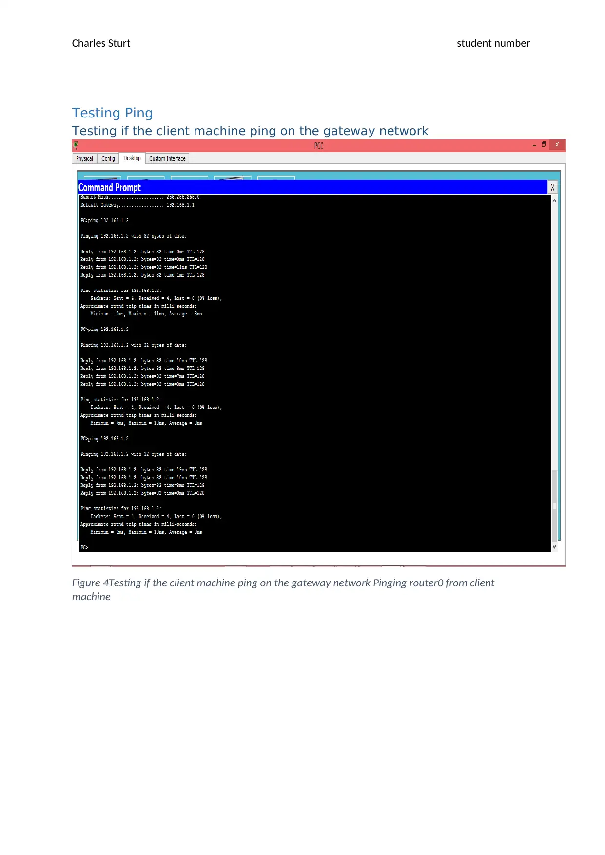
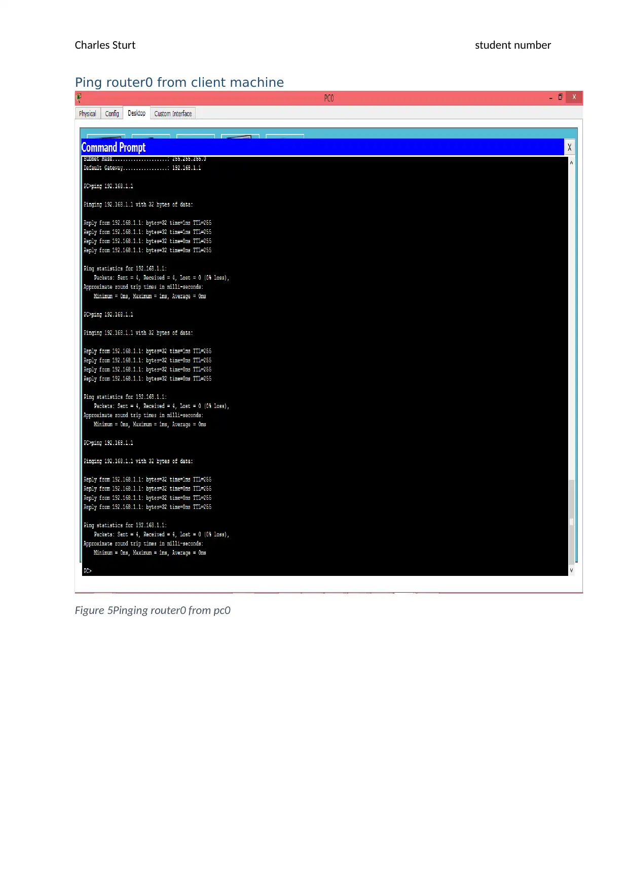
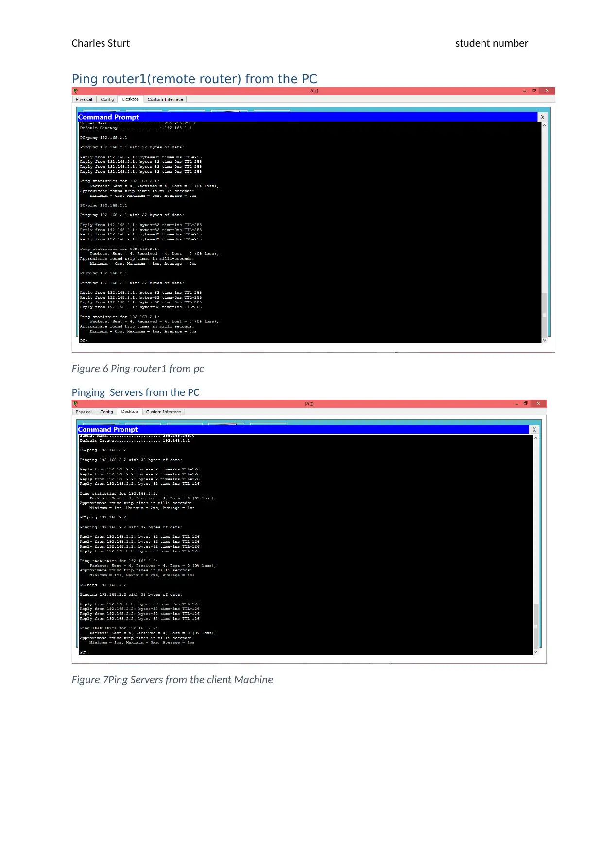
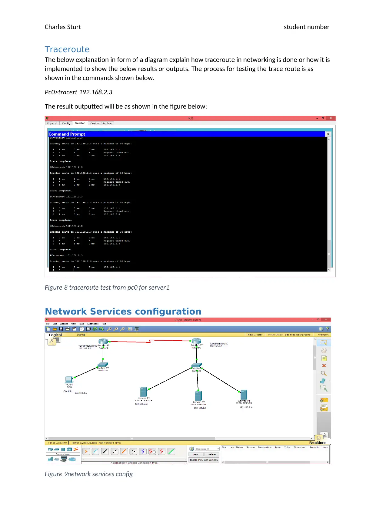
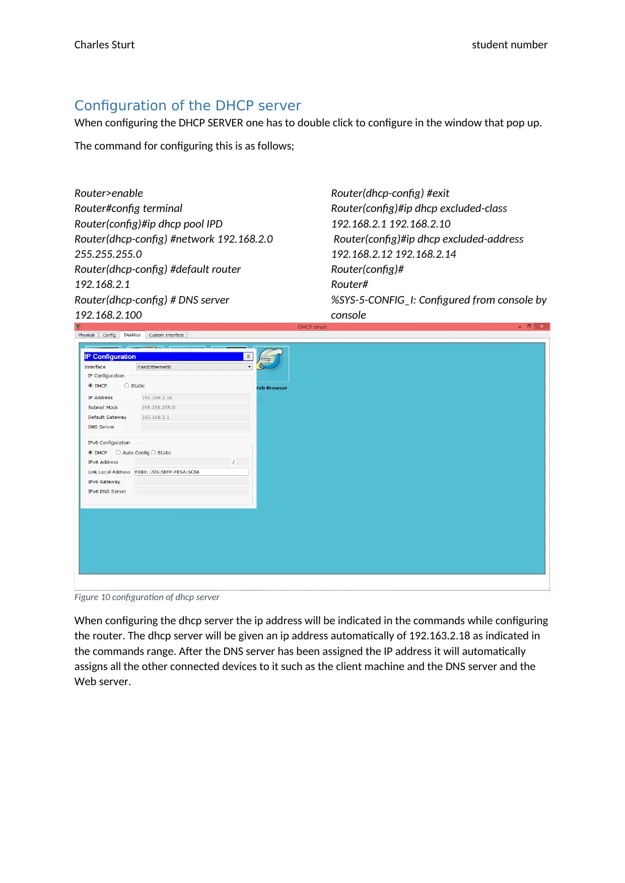
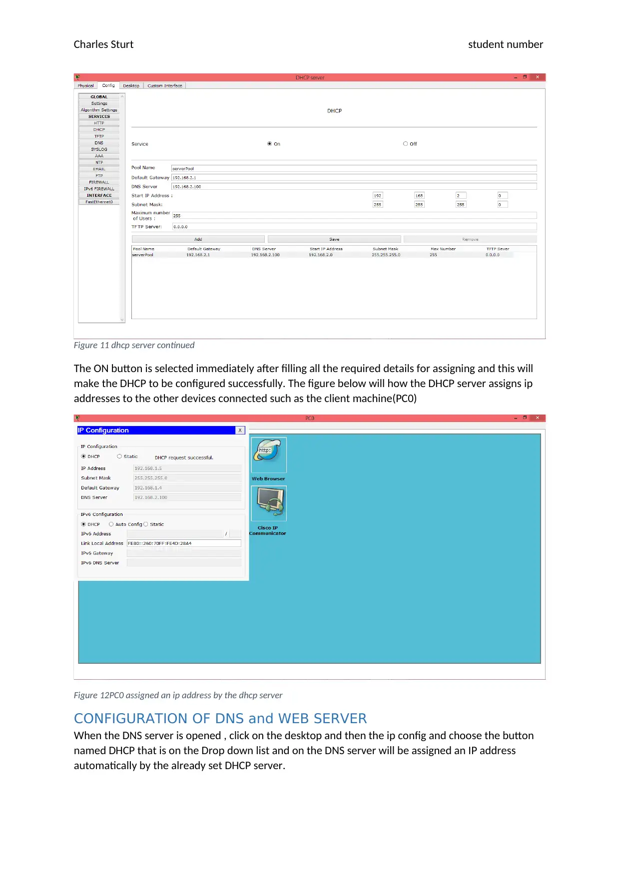
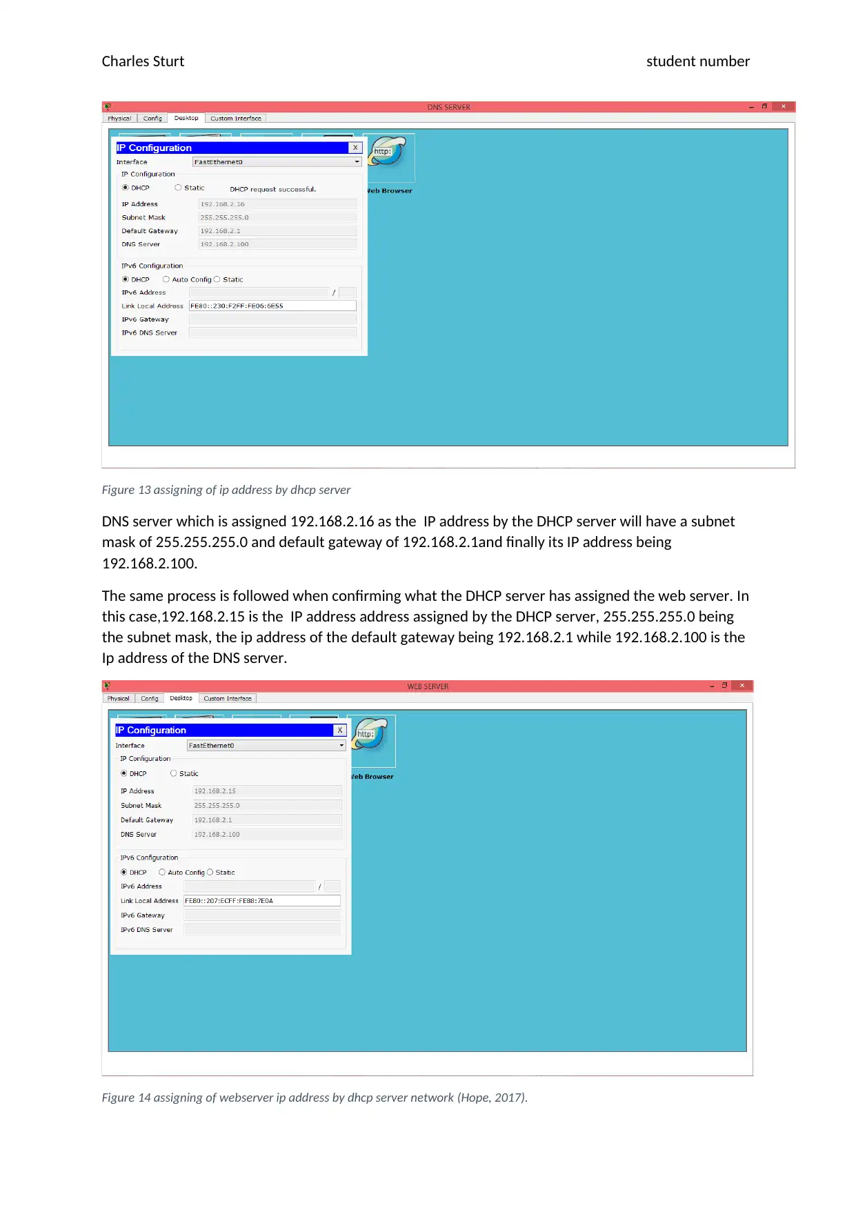
This project details the design and implementation of a network for the fictional company, Techkim. The assignment covers essential aspects of network design, including the configuration of two routers, switches, and servers (DNS, DHCP, and Web servers). It provides a step-by-step guide to router configuration using command-line interfaces, including setting IP addresses, enabling interfaces, and configuring serial connections. The project also demonstrates the setup of DHCP servers for dynamic IP address allocation, along with the configuration of DNS and Web servers. The configuration of a firewall is also included. The project concludes with a discussion of testing the network's functionality through ping and traceroute commands, as well as the configuration of ACLs for security. The goal is to create a scalable and easily manageable network that meets the requirements of the company. The project provides detailed commands, screenshots, and explanations to illustrate the network setup process.

nETWORK DESIGN
ASSESSMENT NO
SEPTEMBER 30, 2017
sTUDENT nAME Student Email
ID
ASSESSMENT NO
SEPTEMBER 30, 2017
sTUDENT nAME Student Email
ID
Paraphrase This Document
Need a fresh take? Get an instant paraphrase of this document with our AI Paraphraser

Charles Sturt student number
Executive Summary
When it comes to networking, then we have to understand network design to be one of the most
vital and important area and a lot of understanding will be required when a network need to be set
up. This has resulted to many organizations to have a need to upgrade to ways that are digital in such
a manner they will avoid the paper work. Communication has been made easy and the case of
centralizing it in one place. This has been experienced in areas or cases where Local Area Network
and Wide Area Network and this leads to sharing of information.
Application of the topology will describe how good the design will look like, the topology will differ in
the manner how the IT components, Circuit (cabling is done), Networking cost in terms of the
proposed budget, how extensive it can especially if we consider how compatible it will be with other
network components expanded in the future.
This scenario about the use of this given routers and server and one PC we will use two LAN where
one will be for the client and the other will be for the remote router. Techkim is the company to be
put designed with the network. The main idea in this study will be to show how a stimulated network
design that is proposed can be implemented in real life to come up with a good physical network
design. The configuration will consist of the routers, client machine, switches and the servers that is
the DNS, DHCP and Web Servers configuration respectively.
IT Infrastructure components
Various components that are used when setting up a network design are required to make the set up
desirable and complete. These components may be the IT infrastructure components such as the
hardware components, server components, cabling that is the circuit and the topology applied in
setting this cables and also the software components to be put in place (Cisco, 2013). When the
selected hardware components such as the router, switches, client pcs and others are selected at
least we can know how the arrangement of the network will be like in terms of the set up (Mitchell,
2017).
WAP is a hardware component that will need to be put in to place so that we do not rely only on the
cabling network but we also have a chance to have a wireless network where we can even use our
phones to connect over the network.

Charles Sturt student number
Network Set up
Figure 1 Network set up
The above figure shows the network set up of the two routers, two switches, three servers namely
the DNS, DHCP and the WEB SERVER respectively and the Client machine. The servers are in their
network and the client machine is in another network though the can communicate via the router 1
and 0.
Routers Configuration
router0 configuration
The following commands shows how router0 was configured.
Router>enable
Router#config terminal
Router(config)#interface fa0/0
Router(config-if)#ip address 192.168.1.1 255.255.255.0
Router(config-if)#no shutdown
Router(config-if)#Exit
%LINK-5-CHANGED: Interface FastEthernet0/0, changed state to up
Router(config)#interface se2/0
Router(config-if)#ip address 192.168.2.1 255.255.255.0
Router(config-if)#clock rate 64000
Router(config-if)#no shutdown
%LINK-5-CHANGED: Interface Serial2/0, changed state to down
Router(config-if)#
%LINK-5-CHANGED: Interface Serial2/0, changed state to up
%LINEPROTO-5-UPDOWN: Line protocol on Interface Serial2/0, changed state to up
⊘ This is a preview!⊘
Do you want full access?
Subscribe today to unlock all pages.

Trusted by 1+ million students worldwide

Charles Sturt student number
Figure 2 router0 configuration
After setting all the commands the state of the router goes up and a green colour appears and the
communication with the devices connected to it becomes complete.
router1 configuration
The command for configuring router1(IP packet forwarding)
Router>enable
Router#config terminal
Router(config-if)#interface fa0/0
Router(config-if)#ip address 192.168.2.1 255.255.255.0
Router(config-if)#no shutdown
Router(config-if)#exit
%LINK-5-CHANGED: Interface FastEthernet0/0, changed state to up
%LINEPROTO-5-UPDOWN: Line protocol on Interface FastEthernet0/0, changed state to up
Router(config)#exit
Router#config terminal
Router(config)#interface se2/0
Router(config-if)#ip address 192.168.1.1 255.255.255.0
Router(config-if)#no shutdown
Router(config-if)#exit
Router(config)#
%LINK-5-CHANGED: Interface Serial2/0, changed state to up
%LINEPROTO-5-UPDOWN: Line protocol on Interface Serial2/0, changed state to up
Paraphrase This Document
Need a fresh take? Get an instant paraphrase of this document with our AI Paraphraser

Charles Sturt student number
Figure 3 router1 configuration
After setting the commands the router1 which is remotely supposed to access the router then it will
change all it states to up and now it can communicate with the servers connected to it via a switch
and also communicate with devices in the other network in router0.
Figure 3 router1 configuration
After setting the commands the router1 which is remotely supposed to access the router then it will
change all it states to up and now it can communicate with the servers connected to it via a switch
and also communicate with devices in the other network in router0.

Charles Sturt student number
Testing Ping
Testing if the client machine ping on the gateway network
Figure 4Testing if the client machine ping on the gateway network Pinging router0 from client
machine
Testing Ping
Testing if the client machine ping on the gateway network
Figure 4Testing if the client machine ping on the gateway network Pinging router0 from client
machine
⊘ This is a preview!⊘
Do you want full access?
Subscribe today to unlock all pages.

Trusted by 1+ million students worldwide

Charles Sturt student number
Ping router0 from client machine
Figure 5Pinging router0 from pc0
Ping router0 from client machine
Figure 5Pinging router0 from pc0
Paraphrase This Document
Need a fresh take? Get an instant paraphrase of this document with our AI Paraphraser

Charles Sturt student number
Ping router1(remote router) from the PC
Figure 6 Ping router1 from pc
Pinging Servers from the PC
Figure 7Ping Servers from the client Machine
Ping router1(remote router) from the PC
Figure 6 Ping router1 from pc
Pinging Servers from the PC
Figure 7Ping Servers from the client Machine

Charles Sturt student number
Traceroute
The below explanation in form of a diagram explain how traceroute in networking is done or how it is
implemented to show the below results or outputs. The process for testing the trace route is as
shown in the commands shown below.
Pc0>tracert 192.168.2.3
The result outputted will be as shown in the figure below:
Figure 8 traceroute test from pc0 for server1
Network Services configuration
Figure 9network services config
⊘ This is a preview!⊘
Do you want full access?
Subscribe today to unlock all pages.

Trusted by 1+ million students worldwide

Charles Sturt student number
Configuration of the DHCP server
When configuring the DHCP SERVER one has to double click to configure in the window that pop up.
The command for configuring this is as follows;
Router>enable
Router#config terminal
Router(config)#ip dhcp pool IPD
Router(dhcp-config) #network 192.168.2.0
255.255.255.0
Router(dhcp-config) #default router
192.168.2.1
Router(dhcp-config) # DNS server
192.168.2.100
Router(dhcp-config) #exit
Router(config)#ip dhcp excluded-class
192.168.2.1 192.168.2.10
Router(config)#ip dhcp excluded-address
192.168.2.12 192.168.2.14
Router(config)#
Router#
%SYS-5-CONFIG_I: Configured from console by
console
Figure 10 configuration of dhcp server
When configuring the dhcp server the ip address will be indicated in the commands while configuring
the router. The dhcp server will be given an ip address automatically of 192.163.2.18 as indicated in
the commands range. After the DNS server has been assigned the IP address it will automatically
assigns all the other connected devices to it such as the client machine and the DNS server and the
Web server.
Paraphrase This Document
Need a fresh take? Get an instant paraphrase of this document with our AI Paraphraser

Charles Sturt student number
Figure 11 dhcp server continued
The ON button is selected immediately after filling all the required details for assigning and this will
make the DHCP to be configured successfully. The figure below will how the DHCP server assigns ip
addresses to the other devices connected such as the client machine(PC0)
Figure 12PC0 assigned an ip address by the dhcp server
CONFIGURATION OF DNS and WEB SERVER
When the DNS server is opened , click on the desktop and then the ip config and choose the button
named DHCP that is on the Drop down list and on the DNS server will be assigned an IP address
automatically by the already set DHCP server.

Charles Sturt student number
Figure 13 assigning of ip address by dhcp server
DNS server which is assigned 192.168.2.16 as the IP address by the DHCP server will have a subnet
mask of 255.255.255.0 and default gateway of 192.168.2.1and finally its IP address being
192.168.2.100.
The same process is followed when confirming what the DHCP server has assigned the web server. In
this case,192.168.2.15 is the IP address address assigned by the DHCP server, 255.255.255.0 being
the subnet mask, the ip address of the default gateway being 192.168.2.1 while 192.168.2.100 is the
Ip address of the DNS server.
Figure 14 assigning of webserver ip address by dhcp server network (Hope, 2017).
⊘ This is a preview!⊘
Do you want full access?
Subscribe today to unlock all pages.

Trusted by 1+ million students worldwide
1 out of 16
Related Documents

Your All-in-One AI-Powered Toolkit for Academic Success.
 +13062052269
info@desklib.com
Available 24*7 on WhatsApp / Email
Unlock your academic potential
Copyright © 2020–2025 A2Z Services. All Rights Reserved. Developed and managed by ZUCOL.