Civil Engineering Report: Childcare Centre Feasibility Study

Verified

Added on  2023/06/08

|21
|1893
|356
Report
AI Summary
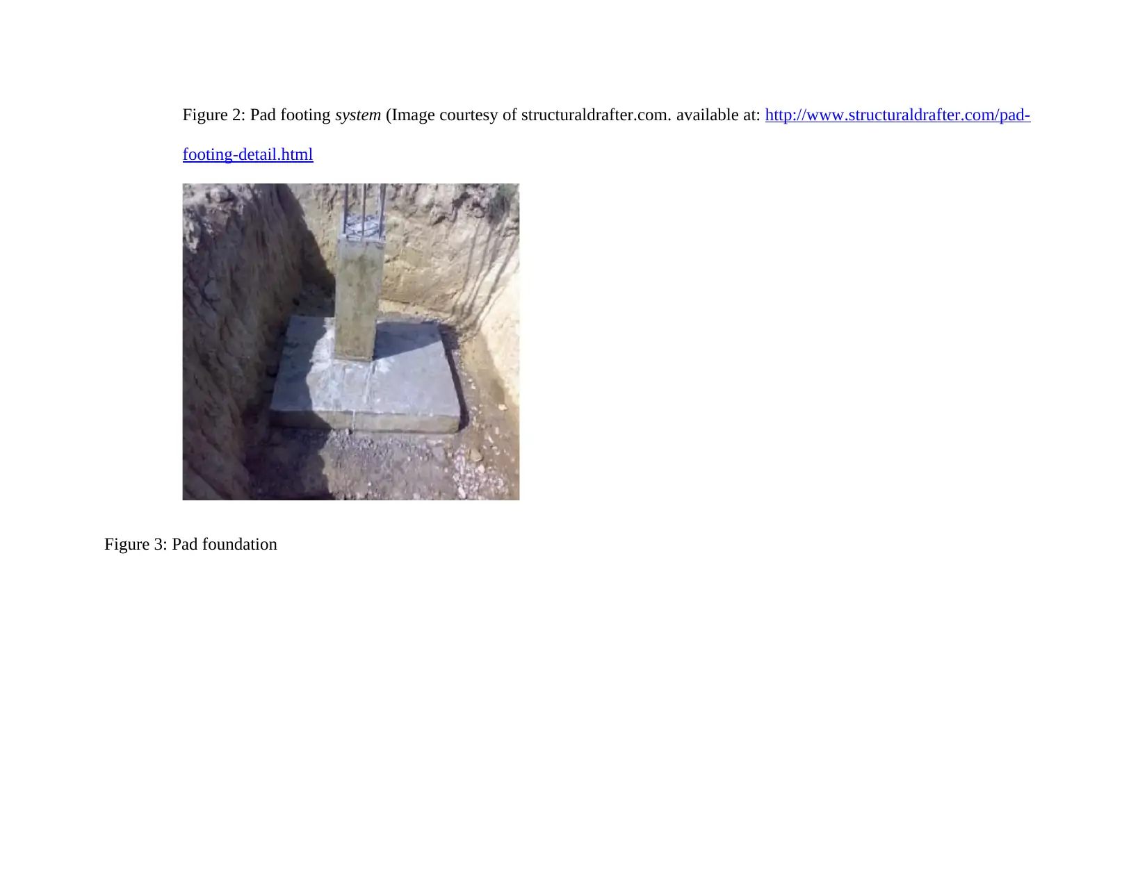
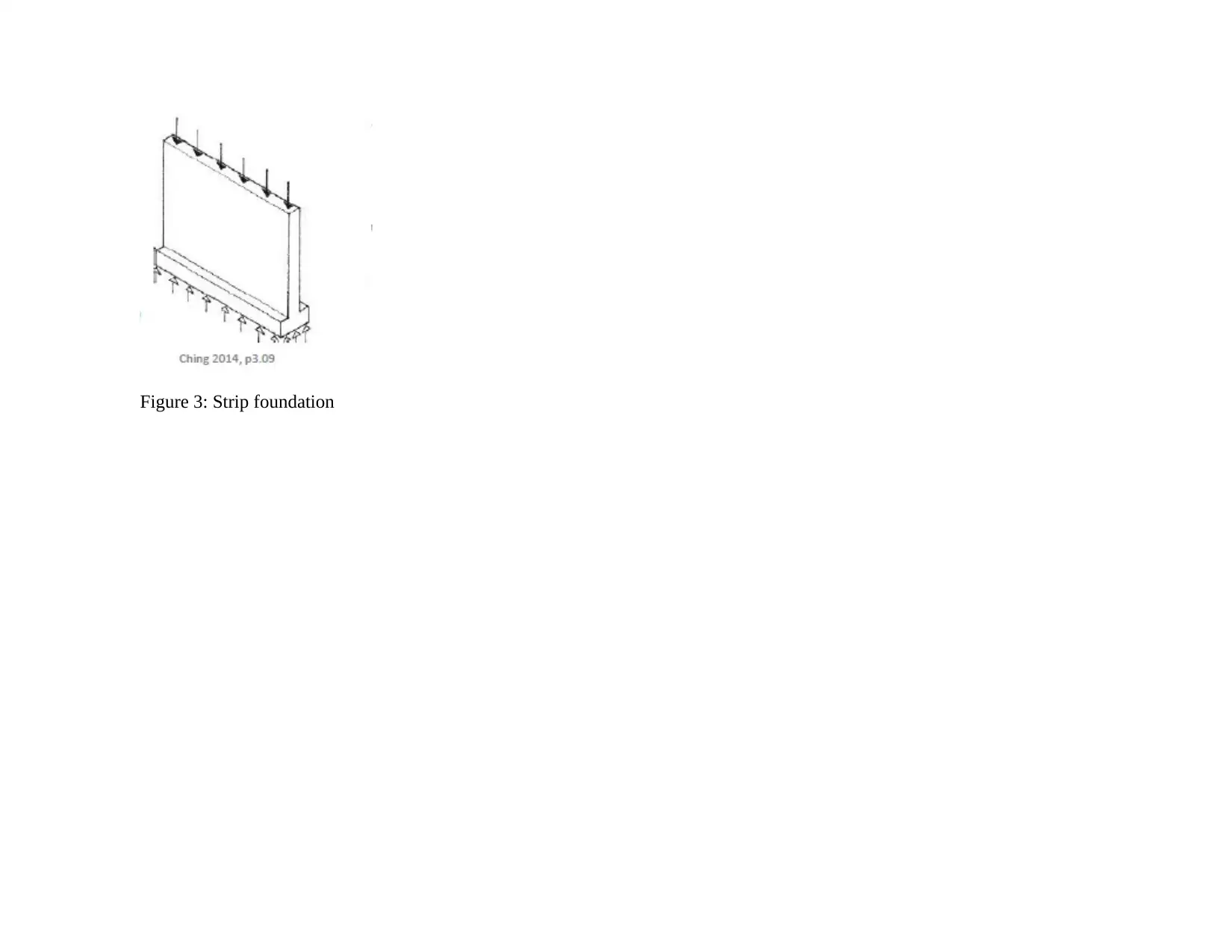
This report presents a feasibility study for a childcare center project, focusing on the selection of appropriate foundation and flooring systems. The study begins with an executive summary that highlights the critical importance of properly designed foundations and flooring systems, adhering to local and national construction codes. The project is located in Charlestown, NSW, Australia. The report provides technical details on the site conditions, including soil types, topography, and potential environmental factors. It compares pad and strip foundations, considering factors such as soil bearing capacity, the impact of nearby trees, and potential ground water changes. The report also examines concrete and composite flooring systems. The conclusion recommends a pad foundation and a composite flooring system, considering site conditions, building classification, and cost constraints. References to relevant publications and resources are included.
tabler-icon-diamond-filled.svg

Contribute Materials

Your contribution can guide someone’s learning journey. Share your documents today.
Document Page
CONSULTANT’S REPORT ON THE FEASIBILITY OF THE AVAILABLE FOUNDATION AND FLOORING
SYSTEMS OPTIONS
PREPARED BY
DATED
LECTURER
DEPARTMENT
tabler-icon-diamond-filled.svg

Secure Best Marks with AI Grader

Need help grading? Try our AI Grader for instant feedback on your assignments.
Document Page
1. EXECUTIVE SUMMARY
Foundations and flooring systems in a building are the most critical elements that must properly be designed. This must follow both
local and national construction codes. For example, we must first establish the type of soil to be encountered so that the type of
foundation selected will match with the prevailing geotechnical information. The report entails technical details on the feasibility
study for Child Care Centre project. Specifically, it provides technical details on the foundation and flooring options.
Project Technical details
The site to be developed is located in Charlestown NSW Australia on the North eastern side of pacific highway, sandwiched by
Kahibah road and George Street. It is generally scrub vegetation with a few trees along the site edges. The topography is gently
sloping with predominant mix of clay and sandy soils. The ground slopes towards the Karibah road in the South East region. The
development entails construction of Child care centre project; a low rise commercial building. The architectural design was done by
Daryl Jackson Robindyke Pty Ltd and therefore, a bulk of this report was derived from the designs.
Document Page
Figure 1: Basic plan of the proposed childcare development (from the architectural drawings)
2. FOUNDATION SYSTEM
(a) Characteristics of the buildings and site conditions
It is generally scrub vegetation with a few trees along the site edges. The topography is gently sloping with predominant
mix of clay and sandy soils. It slopes towards the Karibah in the South East region. However, it is surrounded by other
buildings from all sides hence making it difficult to maneuver with construction materials. From the geotechnical
Document Page
information, rocks and cohesive soils are predominant in Charlestown square. The average soil bearing capacity is between
75 and 150 kN/m2. Due to the nearby growing trees especially in the western side of the building site, cracking of the
walling element due to moisture absorption is inevitable. There are also possible vibrations due to nearby traffic hence this
must also be considered during foundation design and selection. Settlement due to ground water change is also likely to
occur. In soft clay, if the building loads are unmatched, sinking is inevitable and this may cause catastrophic failures such
as overturning.
(b) Comparison of the alternative solution methods
Foundation is the lower portion of a building which rests on the earth and is normally designed to carry both live and dead
loads of the walling element while adequately resisting some movements due to soil condition in which it is established. The
substructure therefore is that portion of a building sunk in the ground while the substructure is erected outside such that load
path is from the roof via the walling element into the foundation. The live loads could be due to wind actions or soil actions
among others like rain water, snow and occupants while the dead loads are imposed by the weight of the roof and walling
elements. Commonly, for residential low rise buildings (like the child care centre development), the best alternative
foundations to consider are either pad or strip foundation. Hence these two are reviewed and the best match will be selected.
From the architectural drawings provided, it can be deduced that the buildings is low rise hence most loading is transmitted
horizontally. However, a strong foundation must still be built.
tabler-icon-diamond-filled.svg

Secure Best Marks with AI Grader

Need help grading? Try our AI Grader for instant feedback on your assignments.
Document Page
(i) Pad foundation
This is the most appropriate foundation system for both medium and low rise building structure as each foundation is
independent of each other and they can have different designs catering for the various imposed loads. This makes them ideal
for both symmetrical and unsymmetrical floor plans and building shapes. The load in this case is transferred directly from the
columns into the footing and in some case; more than one column can reside on a single pad footing. This type of footing is
applicable in a wide variety of structural systems ranging from ordinary moment resisting frames and portal frames to shear
wall building frames. This therefore means that they can be used on almost every building material from concrete to stone.
Notably, however, the area in which the building is to be seated is in one of the streets of Charlestown and from various soil
tests carried out, it reveals that clay soils could be dominating implying that the soils are verily reactive (this is categorized as
class H according to AS 2870 and AS 1726) hence need to integrate another foundation type to accommodate the changing soil
properties like moisture content. AS 2870 provides further technical requirements for this kind of foundation. Nevertheless,
pad footings are only applicable in providing support to the columns hence it is normally restrictive to localized vertical
support. In the drawing plan, position of piers to be sunk provides a rough indication of the exact location of these pad
foundations as they are linked directly. Besides, safeguards on shear and bending moments will only be sufficient if the
concrete mix strength and the reinforcement are appropriately done (Murty et al, 2002). Area of the foundation often depend
on load to be transmitted, bearing and shear strength of the soils, thickness, exaction method adopted and the concrete
formwork.
Document Page
Table 1: Comparing Pad and Strip foundations
PAD FOUNDATION STRIP FOUNDATION
Ideal for symmetric plans since it is isolated Safeguards against shear and bending
Ideal for moment resisting frames and portal frames Accommodates swelling and shrinkage of reactive soils
Restricted to localized vertical supports Firm structure provisions
Document Page
(i) Strip footing
Wide strip foundation often comes in handy in conditions of extreme swelling and shrinkage. They have more advantages over
other systems as they allow for either one or more basement levels while being relatively unaffected by changing soil
conditions. The strips provide a firm foundation structure against such movements as they are sunk deeper than the normal
tabler-icon-diamond-filled.svg

Paraphrase This Document

Need a fresh take? Get an instant paraphrase of this document with our AI Paraphraser
Document Page
foundation. It is suitable for this type of dwelling as its applicability ranges from low to medium rise constructions. Since soils
in Charlestown square are predominantly clay, we will need a thick and wide strip all round.
(c) Graphical information for the proposed solutions
Document Page
Figure 2: Pad footing system (Image courtesy of structuraldrafter.com. available at: http://www.structuraldrafter.com/pad-
footing-detail.html
Figure 3: Pad foundation
Document Page
Figure 3: Strip foundation
tabler-icon-diamond-filled.svg

Secure Best Marks with AI Grader

Need help grading? Try our AI Grader for instant feedback on your assignments.
Document Page
Figure 4: Position of piers in the building plan
3. FLOORING SYSTEM
(a) Comparison of the alternative solution methods
The options available for consideration in this section include: concrete and composites flooring systems.
(i) Concrete flooring systems
From the architectural drawings, it can be observed that most of the design elements are in tandem with a concrete screed floor
system. In the building in our case, the screed is applied on top of the existing concrete slab and from there any other floor
Document Page
finishes can be applied as per the specifications of the occupants. In most cases there is usually a series of ground beams on
which the concrete slab rests and the architectural drawings gives an indication of the same. The concrete slab is reinforced
before concreting to make it stronger and it is then possible to carry loads imposed on the floor as per the design (Nawy,
2000).
Figure 5: waterproofing in concrete flooring system
Document Page
(ii) Composites flooring system
Instead of the conventional concrete reinforcements where meshes are used; this case utilizes fiber composites providing
same strength characteristics as the conventional flooring system. It has the best quality of finish and it is less expensive in
construction as meshes are eliminated. During construction, incidences of safety are reduced as handling is minimized.
Besides, it greatly saves on concrete. Tripping hazards are also reduced.
Table2: Comparison of the flooring systems options
Concrete flooring Woode
n
floorin
g
Composite
Mostly fire resilient due to noncombustible material
mix
May be
compos
ed of
flamma
ble
No meshes required hence cost
effective as concrete amounts are
reduced
tabler-icon-diamond-filled.svg

Paraphrase This Document

Need a fresh take? Get an instant paraphrase of this document with our AI Paraphraser
Document Page
chemic
als in
form of
adhesiv
es
Integrates well with the health and wellbeing since it
is chemically inert. For instance preservatives are
not used and no special coatings required hence
boosting wellbeing of occupants
Fragilit
y is
higher
making
less
applica
ble in
areas
that
Better strength characteristics
exhibited than the conventional
concrete flooring
Document Page
experie
nce
impacts
from
falling
objects
Has better acoustic performance since it dimly
absorbs sound
May
not
have
better
acousti
c
perfor
mance
Has excellent crack control ability
Document Page
Resilient to flooding since they are often poured on
top of waterproofing layer
Due to
use of
sealers
in
which
Minimized tripping hazards on the
site
tabler-icon-diamond-filled.svg

Secure Best Marks with AI Grader

Need help grading? Try our AI Grader for instant feedback on your assignments.
Document Page
case
some
may
not be
waterpr
oof,
challen
ges of
waterpr
oofing
may
recur
Resilient to periodic changes in climatic conditions
hence cushioning the interior against extreme
external conditions
Due to
crevice
s
induce
There is often minimized handling
such that earth movers such as
cranes are unnecessary
Document Page
d, it
may
not
very
well
cushion
ing
against
extrem
e
climati
c
conditi
ons
Document Page
(b) Graphical information for the proposed solutions
Figure 4: The typical concrete flooring system ( Image courtesy of Idrus, 2008)
4. CONCLUSION AND RECOMMENDATION
From the above technical description of the available option, it can safely be said that the best foundation that matches the site
conditions and the planned development is pad foundation. Flooring system to be used in this case should be the composite system as
tabler-icon-diamond-filled.svg

Paraphrase This Document

Need a fresh take? Get an instant paraphrase of this document with our AI Paraphraser
Document Page
it greatly matches with the site conditions and the building design. The superstructure which is composed of walling and roofing
elements are to be built such that walling materials will mainly be masonry and concrete for the columns; the truss of the roof will be
made of timber for all of the rooms in the building. This can be deduced from the drawings provided. The major criteria for selection
were the site condition, the purpose of the building, the building classification and the cost constraints.
REFERENCES
Idrus, A. (2008). Evaluating Construction Time Performance of Building Floor System Design at the (Early) Conceptual Design
Stage. Selangor University of Industry (UNISEL), Jalan Zirkon. Pg 2.
Kingspan. (2018). Composite Slab Flooring System. Sherburn, Malton, North Yorkshire Available at:www.kingspanstructural.com
Murty, C. V. R., et al. (2002). "Reinforced concrete structures." Earthquake spectra 18.S1: 149-185.
Nawy, E.(2000). Reinforced concrete: A fundamental approach. Available at: http://www.structuraldrafter.com/pad-footing-
detail.html.
Document Page
chevron_up_icon
1 out of 21
circle_padding
hide_on_mobile
zoom_out_icon
logo.png

Your All-in-One AI-Powered Toolkit for Academic Success.

Available 24*7 on WhatsApp / Email

[object Object]