University Circuit Fundamentals Lab 2 Report: Kirchhoff's Laws
VerifiedAdded on 2022/10/16
|7
|1008
|136
Report
AI Summary
This lab report details an experiment on circuit fundamentals, focusing on Kirchhoff's current and voltage laws. The objectives included practical investigation of these laws, application of voltage and current divider rules, examination of currents and voltages at a node, and the effects of a short circuit. The experiment involved using a power supply, breadboard, digital multimeter, resistors, and connecting wires. Procedures included measuring resistor values, assembling circuits, and recording voltage and current measurements. The results section presents calculated and measured values for total resistance, voltages across resistors, and currents through resistors. Percentage errors were calculated to compare measured and calculated values, verifying Kirchhoff's laws. The report also examined the effects of short circuits on voltage drops. The conclusion confirms the successful verification of Kirchhoff's laws and the investigation of short circuit effects. The report includes tables of results and discussions of the findings.
1
Lab 2 Report: Circuit Fundamentals
The aims and objectives for this lab exercise include
1. To investigate Kirchhoff’s current and voltage laws practically
2. To apply voltage and current divider rules to determine voltage and current
3. To examine currents and voltages at a node
4. To investigate the effects of a short circuit on voltage and current
5. To revisit ohm’s law investigated in lab 1 exercise
Apparatus used
1. Power supply
2. Bread board
3. Digital multimeter
4. Resistors
5. Connecting wires
Procedure
The activities carried out in the first laboratory exercise were revisited. These include the
calculation of the total resistance, currents through the resistors, voltages across the resistors
and the sum of all voltages. The supply voltage was maintained at 8 V.
Part one of the lab exercise involved taking measurements to study Kirchhoff’s voltage law.
An ohmmeter was used to record the values of the resistors. The circuit was then assembled
Paraphrase This Document
Need a fresh take? Get an instant paraphrase of this document with our AI Paraphraser
2
and the voltages across each resistor as well as the currents recorded. For voltage
measurement, the red probe of the multimeter was connected at the desired point and the
black probe connected to the reference point. For current measurement, the circuit must be
broken and the multimeter connected between the resistors. The percentage difference
between measured and recorded values was then calculated.
Part one of the lab exercise involved taking measurements to study Kirchhoff’s current law.
The circuit provided in the laboratory manual was constructed on the bread board and the
voltage across the resistors recorded. The currents through the resistors were also recorded.
The percentage difference between the measured and calculated values was then computed.
Further measurements were taken for more than 1 resistors having a resistance of 330 ohms.
Figures
Results and discussion
With the circuits connected as directed in the laboratory manual, the values of total
resistance, the voltages across the individual resistors, and the currents through the resistors
were calculated and recorded in the table shown below. The supply voltage was maintained at
8 V.
Another circuit was set up according to the manual and the values for currents, voltages
across each resistor and the total resistance recorded. The results were recorded in the table
below.

3
Part 1: Kirchhoff’s voltage law
The values for the provided resistors were measured and recorded in the table below with a
supply voltage of 8 V. the percentage error was then calculated for each resistor using the
nominal values and the formula below,
% Error= Measured Value−Nominated Value
Nominated Value ∗100
After recording the measured resistance, currents and voltages for each resistor. The
percentage error was calculated using the above formula and the results recorded in the table
below.
⊘ This is a preview!⊘
Do you want full access?
Subscribe today to unlock all pages.

Trusted by 1+ million students worldwide
4
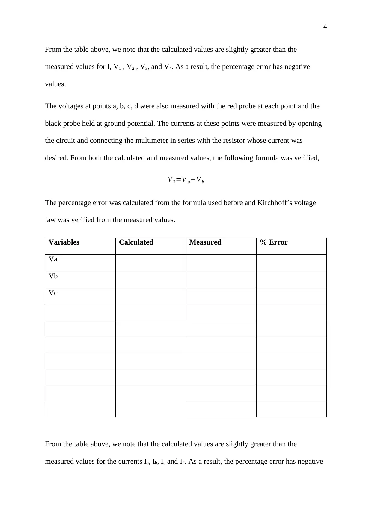
From the table above, we note that the calculated values are slightly greater than the
measured values for I, V1 , V2 , V3, and V4. As a result, the percentage error has negative
values.
The voltages at points a, b, c, d were also measured with the red probe at each point and the
black probe held at ground potential. The currents at these points were measured by opening
the circuit and connecting the multimeter in series with the resistor whose current was
desired. From both the calculated and measured values, the following formula was verified,
V 2=V a−V b
The percentage error was calculated from the formula used before and Kirchhoff’s voltage
law was verified from the measured values.
Variables Calculated Measured % Error
Va
Vb
Vc
From the table above, we note that the calculated values are slightly greater than the
measured values for the currents Ia, Ib, Ic and Id. As a result, the percentage error has negative
From the table above, we note that the calculated values are slightly greater than the
measured values for I, V1 , V2 , V3, and V4. As a result, the percentage error has negative
values.
The voltages at points a, b, c, d were also measured with the red probe at each point and the
black probe held at ground potential. The currents at these points were measured by opening
the circuit and connecting the multimeter in series with the resistor whose current was
desired. From both the calculated and measured values, the following formula was verified,
V 2=V a−V b
The percentage error was calculated from the formula used before and Kirchhoff’s voltage
law was verified from the measured values.
Variables Calculated Measured % Error
Va
Vb
Vc
From the table above, we note that the calculated values are slightly greater than the
measured values for the currents Ia, Ib, Ic and Id. As a result, the percentage error has negative
Paraphrase This Document
Need a fresh take? Get an instant paraphrase of this document with our AI Paraphraser
5
values. The percentage error for the remaining values is zero since the current in the series
circuit remains the same.
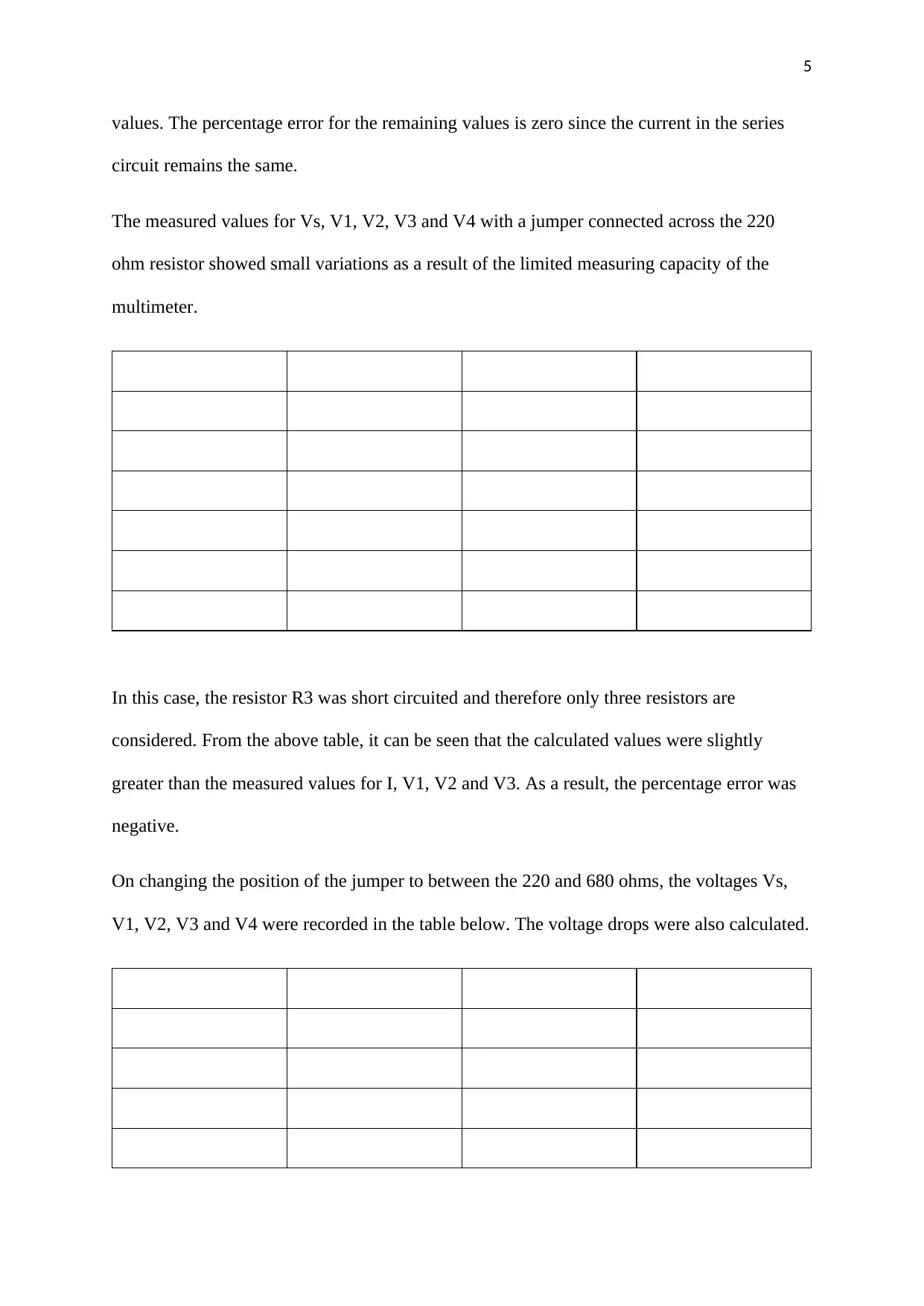
The measured values for Vs, V1, V2, V3 and V4 with a jumper connected across the 220
ohm resistor showed small variations as a result of the limited measuring capacity of the
multimeter.
In this case, the resistor R3 was short circuited and therefore only three resistors are
considered. From the above table, it can be seen that the calculated values were slightly
greater than the measured values for I, V1, V2 and V3. As a result, the percentage error was
negative.
On changing the position of the jumper to between the 220 and 680 ohms, the voltages Vs,
V1, V2, V3 and V4 were recorded in the table below. The voltage drops were also calculated.
6
Part 2: Kirchhoff’s current law
After assembling the circuit, it was powered using a supply voltage of 8 V. The voltages
across each resistor and the currents through them were measured and recorded. A
comparison between the measured and the calculated values shows that they are almost the
same. The small difference may be attributed to voltage drops. Kirchhoff’s current law was
verified using the measured values and the equation below,
∑ I¿=∑ IOUT
Currents I3 and I4 are the same since the resistors are connected in series. The percentage
error for the measured and calculated values was computed and the results recorded in the
table below
⊘ This is a preview!⊘
Do you want full access?
Subscribe today to unlock all pages.

Trusted by 1+ million students worldwide
7
From the table above, we note that the calculated values are slightly greater than the
measured values for I2, I3, I4, V2, V3 and V4. As a result the percentage error has negative
values.
Conclusion
In this laboratory exercise, both Kirchhoff’s voltage and current laws were examined and
verified. The effect of a short circuit on the circuit parameters was also investigated and
shown to cause zero voltage drop across resistors. The objectives set were therefore achieved.
1 out of 7
Related Documents
Your All-in-One AI-Powered Toolkit for Academic Success.
+13062052269
info@desklib.com
Available 24*7 on WhatsApp / Email
![[object Object]](/_next/static/media/star-bottom.7253800d.svg)
Unlock your academic potential
Copyright © 2020–2026 A2Z Services. All Rights Reserved. Developed and managed by ZUCOL.


