Electrical and Electronic Principles Circuit Theory TMA
VerifiedAdded on 2022/10/14
|13
|374
|15
Homework Assignment
AI Summary
This document presents a comprehensive solution to a Circuit Theory assignment, likely for an Electrical and Electronic Principles module. The assignment covers various fundamental concepts including Thevenin's theorem, Superposition theorem, and Norton's theorem, illustrating their application through detailed calculations and circuit analysis. It also includes solutions using mesh analysis and nodal analysis to solve complex circuits. Furthermore, the assignment explores topics like star-delta transformations and resonance in parallel circuits. The solutions are presented step-by-step with clear explanations, making it an excellent resource for students studying electrical engineering and circuit analysis. This assignment is a valuable resource available on Desklib, a platform providing students with access to past papers and solved assignments to aid in their studies.
Running head: CIRCUIT THEORY 1
Circuit Theory
Name
Institution
Circuit Theory
Name
Institution
Paraphrase This Document
Need a fresh take? Get an instant paraphrase of this document with our AI Paraphraser
CIRCUIT THEORY 2
Circuit Theory Homework
Question 1
Part a (Thevenin Theorem)
V 1= √2 × 415cos ( 100 πt ) , V 1 ( RMS )=415 ∠ 90 °
V 2= √2 × 415sin ( 100 πt ) , V 2 ( RMS )=415∠0 °
We use the RMS values of V 1 and V 2
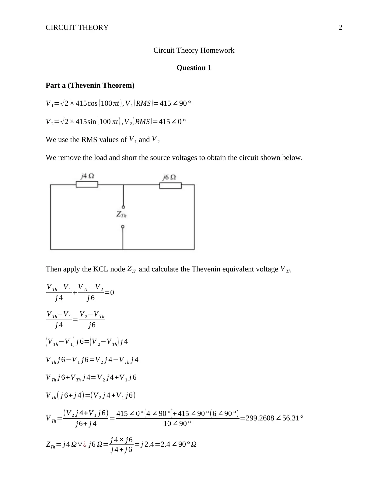
We remove the load and short the source voltages to obtain the circuit shown below.
Then apply the KCL node ZTh and calculate the Thevenin equivalent voltage V Th
V Th−V 1
j 4 + V Th−V 2
j 6 =0
V Th−V 1
j 4 = V 2−V Th
j6
( V Th−V 1 ) j 6= ( V 2−V Th ) j 4
V Th j 6−V 1 j6=V 2 j 4−V Th j 4
V Th j 6+V Th j 4=V 2 j 4 +V 1 j 6
V Th( j 6+ j 4)=(V 2 j 4 +V 1 j6)
V Th=(V 2 j 4+V 1 j 6)
j6+ j 4 = 415 ∠ 0° ( 4 ∠ 90 ° ) + 415 ∠90 ° (6 ∠ 90 °)
10 ∠ 90 ° =299.2608 ∠ 56.31°
ZTh= j4 Ω∨¿ j6 Ω= j 4 × j6
j 4 + j 6 = j 2.4=2.4 ∠ 90 ° Ω
CIRCUIT THEORY 3
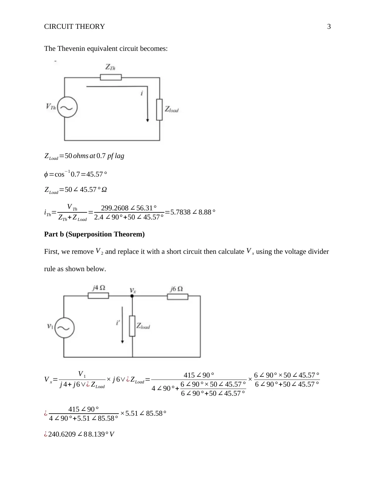
The Thevenin equivalent circuit becomes:
ZLoad =50 ohms at 0.7 pf lag
ϕ =cos−1 0.7=45.57 °
ZLoad =50∠ 45.57 ° Ω
iTh= V Th
ZTh+ Z Load
= 299.2608 ∠56.31°
2.4 ∠90° +50 ∠ 45.57° =5.7838 ∠ 8.88 °
Part b (Superposition Theorem)
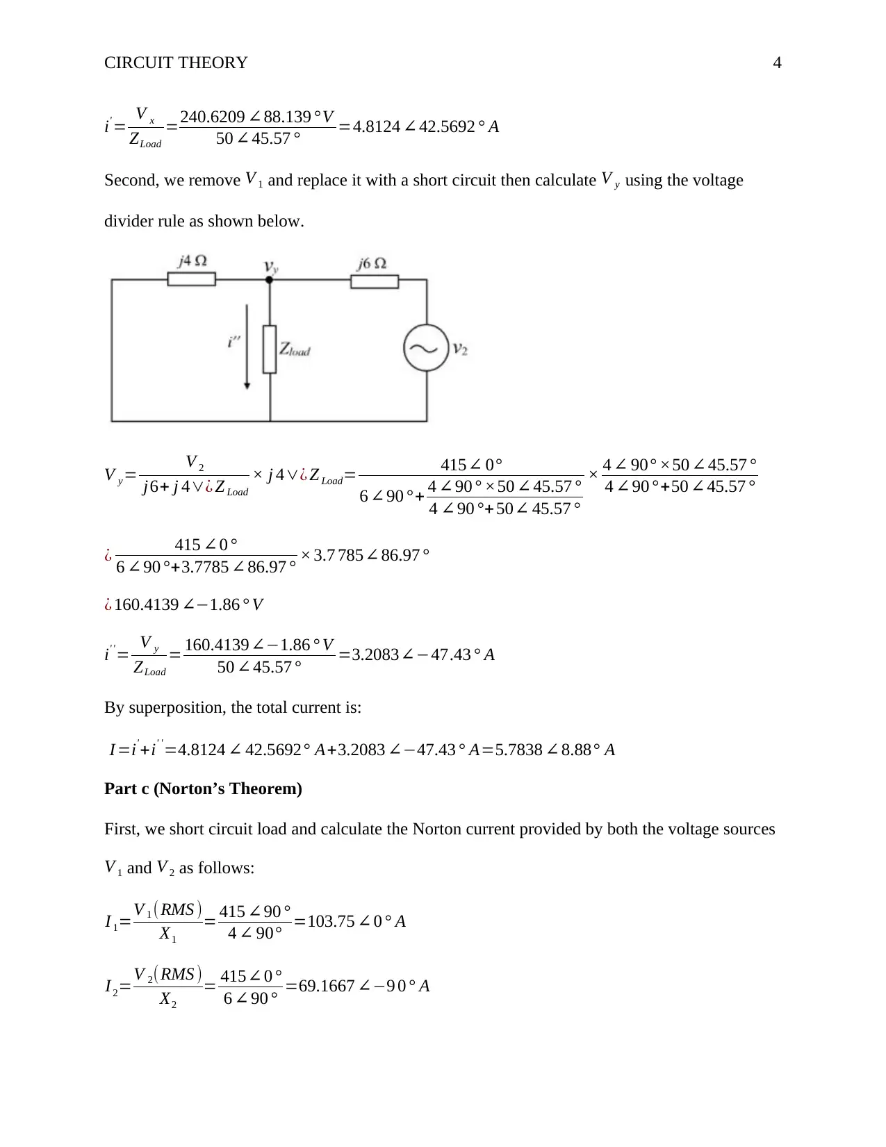
First, we remove V 2 and replace it with a short circuit then calculate V x using the voltage divider
rule as shown below.
V x= V 1
j 4+ j6∨¿ ZLoad
× j 6∨¿ ZLoad = 415 ∠90 °
4 ∠ 90 °+ 6 ∠90 ° × 50∠ 45.57 °
6 ∠90 ° +50 ∠45.57 °
× 6 ∠ 90° ×50 ∠ 45.57 °
6 ∠90 ° +50∠ 45.57 °
¿ 415 ∠ 90 °
4 ∠90 °+5.51 ∠ 85.58° ×5.51∠ 85.58°
¿ 240.6209 ∠8 8.139° V
⊘ This is a preview!⊘
Do you want full access?
Subscribe today to unlock all pages.

Trusted by 1+ million students worldwide
CIRCUIT THEORY 4
i' = V x
ZLoad
=240.6209 ∠88.139 °V
50 ∠ 45.57 ° =4.8124 ∠ 42.5692 ° A
Second, we remove V 1 and replace it with a short circuit then calculate V y using the voltage
divider rule as shown below.
V y= V 2
j6+ j 4∨¿ Z Load
× j 4∨¿ Z Load= 415∠ 0°
6 ∠90 ° + 4 ∠ 90 ° ×50 ∠ 45.57 °
4 ∠ 90 °+ 50∠ 45.57 °
× 4 ∠ 90° ×50 ∠ 45.57 °
4 ∠ 90 ° +50 ∠45.57 °
¿ 415 ∠0 °
6 ∠90 °+3.7785 ∠86.97 ° × 3.7 785∠ 86.97 °
¿ 160.4139 ∠−1.86 ° V
i' '= V y
ZLoad
= 160.4139∠−1.86 ° V
50 ∠ 45.57 ° =3.2083∠−47.43 ° A
By superposition, the total current is:
I =i'+i' '=4.8124 ∠ 42.5692° A+3.2083 ∠−47.43 ° A=5.7838 ∠ 8.88° A
Part c (Norton’s Theorem)
First, we short circuit load and calculate the Norton current provided by both the voltage sources
V 1 and V 2 as follows:
I 1=V 1 (RMS )
X1
= 415 ∠90 °
4 ∠ 90° =103.75 ∠0 ° A
I 2=V 2(RMS )
X2
= 415∠0 °
6 ∠ 90 ° =69.1667 ∠−9 0 ° A
Paraphrase This Document
Need a fresh take? Get an instant paraphrase of this document with our AI Paraphraser
CIRCUIT THEORY 5
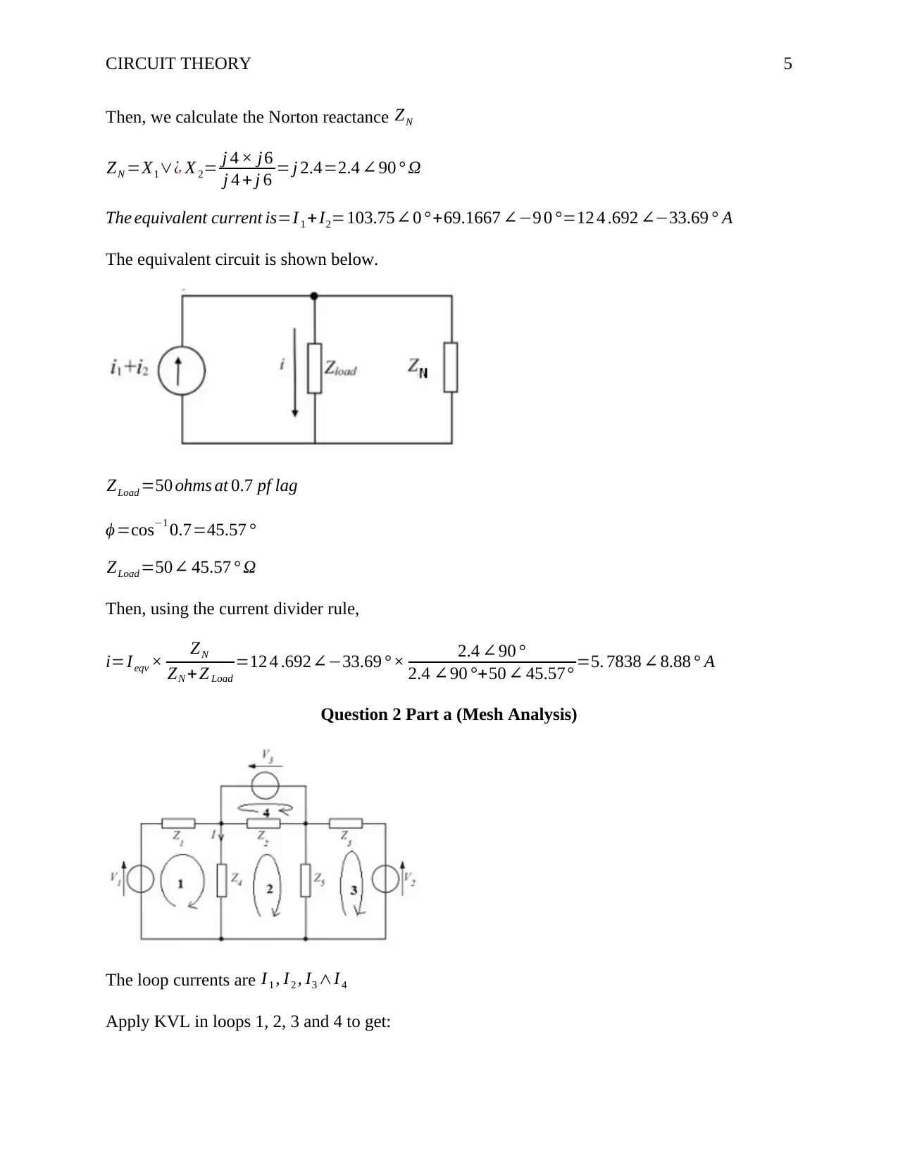
Then, we calculate the Norton reactance ZN
ZN =X1∨¿ X 2= j 4 × j6
j 4 + j 6 = j 2.4=2.4 ∠90 ° Ω
The equivalent current is=I 1 +I2=103.75∠ 0 °+69.1667 ∠−9 0 °=12 4 .692 ∠−33.69 ° A
The equivalent circuit is shown below.
ZLoad =50 ohms at 0.7 pf lag
ϕ =cos−1 0.7=45.57 °
ZLoad =50∠ 45.57 ° Ω
Then, using the current divider rule,
i=Ieqv × ZN
ZN + Z Load
=12 4 .692∠−33.69 °× 2.4 ∠ 90 °
2.4 ∠90 °+50 ∠ 45.57° =5. 7838 ∠ 8.88 ° A
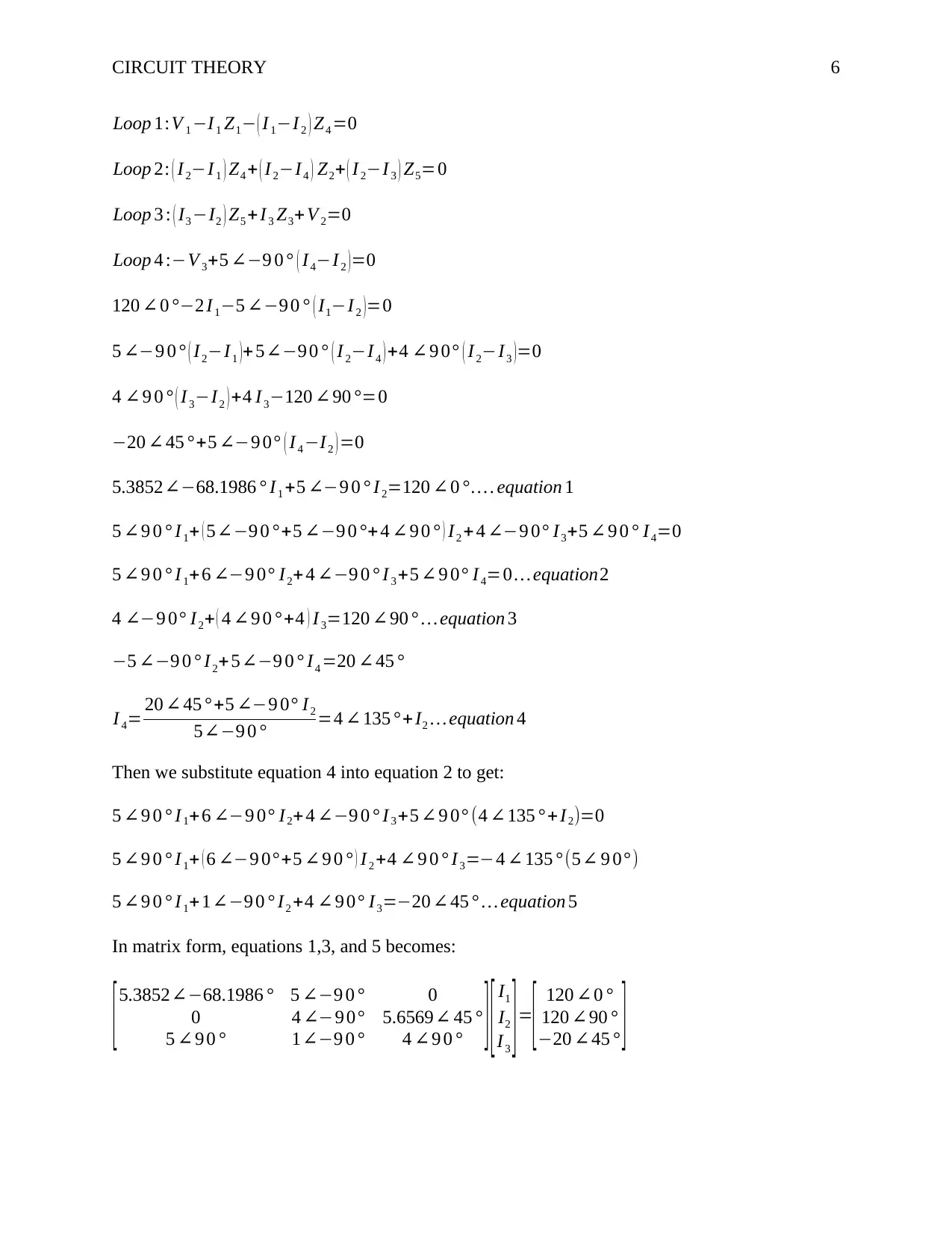
Question 2 Part a (Mesh Analysis)
The loop currents are I 1 , I2 , I3 ∧I 4
Apply KVL in loops 1, 2, 3 and 4 to get:
CIRCUIT THEORY 6
Loop 1:V 1 −I 1 Z1− ( I 1−I 2 ) Z4 =0
Loop 2: ( I 2−I 1 ) Z4 + ( I 2−I4 ) Z2+ ( I 2−I 3 ) Z5=0
Loop 3 : ( I3 −I2 ) Z5 +I 3 Z3+ V 2=0
Loop 4 :−V 3+5 ∠−9 0 ° ( I4−I2 )=0
120 ∠ 0 °−2 I 1−5 ∠−9 0 ° ( I1−I 2 )=0
5 ∠−9 0 ° ( I2−I1 )+ 5∠−9 0 ° ( I 2−I 4 ) +4 ∠9 0° ( I2−I3 )=0
4 ∠ 9 0 ° ( I 3−I2 ) +4 I 3−120 ∠ 90 °=0
−20 ∠ 45 °+5 ∠−9 0° ( I4 −I2 ) =0
5.3852∠−68.1986 ° I1 +5 ∠−9 0 ° I 2=120 ∠ 0 °… . equation 1
5 ∠9 0 ° I 1+ ( 5∠−9 0 °+5 ∠−9 0 °+ 4 ∠ 9 0 ° ) I2 +4 ∠−9 0° I3+5 ∠ 9 0 ° I4=0
5 ∠9 0 ° I 1+ 6 ∠−9 0° I2+ 4 ∠−9 0 ° I 3 +5 ∠ 9 0° I4=0 … equation2
4 ∠−9 0° I2+ ( 4 ∠ 9 0 ° +4 ) I3=120 ∠ 90 ° … equation 3
−5 ∠−9 0 ° I 2+ 5∠−9 0 ° I4 =20 ∠45 °
I 4= 20 ∠ 45 ° +5 ∠−9 0° I2
5∠−9 0 ° =4 ∠ 135 °+ I2 … equation 4
Then we substitute equation 4 into equation 2 to get:
5 ∠9 0 ° I 1+ 6 ∠−9 0° I2+ 4 ∠−9 0 ° I 3 +5 ∠ 9 0° (4 ∠135 ° +I2)=0
5 ∠9 0 ° I 1+ ( 6 ∠−9 0°+5 ∠9 0 ° ) I 2 +4 ∠ 9 0 ° I 3=−4 ∠ 135 ° (5∠ 9 0°)
5 ∠9 0 ° I 1+ 1∠−9 0 ° I2 +4 ∠ 9 0° I3=−20 ∠ 45 ° … equation 5
In matrix form, equations 1,3, and 5 becomes:
[5.3852∠−68.1986 ° 5 ∠−9 0 ° 0
0 4 ∠−9 0° 5.6569∠ 45 °
5 ∠ 9 0 ° 1∠−9 0 ° 4 ∠9 0 ° ] [ I1
I2
I3 ]=
[ 120 ∠0 °
120 ∠90 °
−20 ∠45 ° ]
⊘ This is a preview!⊘
Do you want full access?
Subscribe today to unlock all pages.

Trusted by 1+ million students worldwide
CIRCUIT THEORY 7
[ 2− j5 j5 0
0 − j 4 4+ j 4
j5 − j1 j4 ] [ I1
I2
I3 ]= [ 120
j120
−14.142− j14.142 ]
Solving the matrix using Excel we get:
[ I1
I2
I3 ]=
[ 28.391 ∠−53.692 °
47.816 ∠−57.115°
2 8.536 ∠−50.742 ° ]
I =I1−I2=28.391∠−53.692°−47.816 ∠−57.115°=19.5493∠ 117.91 °
Question 2 Part b (Nodal Analysis)
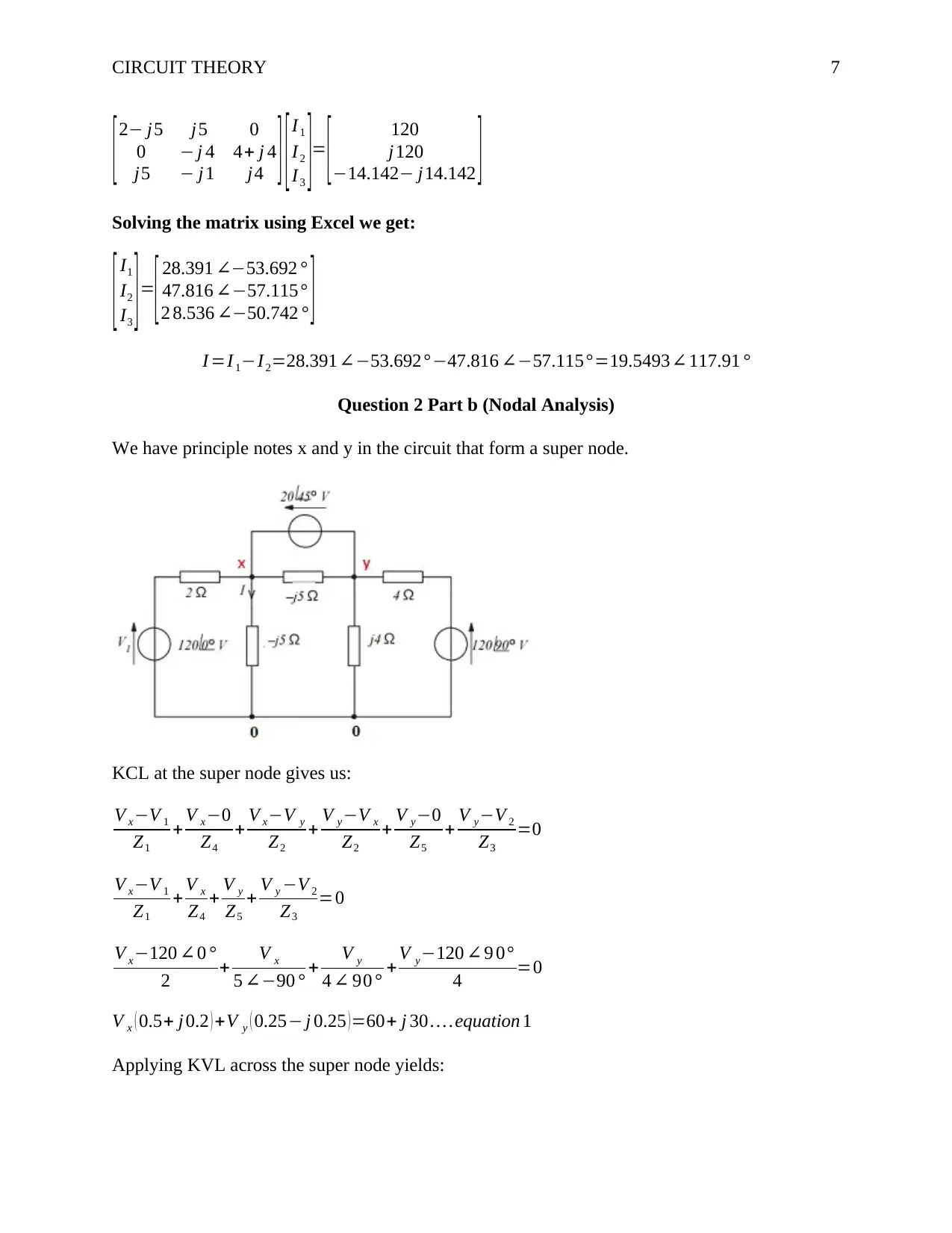
We have principle notes x and y in the circuit that form a super node.
KCL at the super node gives us:
V x−V 1
Z1
+ V x−0
Z4
+ V x−V y
Z2
+ V y−V x
Z2
+ V y−0
Z5
+ V y−V 2
Z3
=0
V x−V 1
Z1
+ V x
Z4
+ V y
Z5
+ V y −V 2
Z3
=0
V x−120 ∠0 °
2 + V x
5 ∠−90 ° + V y
4 ∠ 90 ° + V y−120 ∠9 0°
4 =0
V x ( 0.5+ j 0.2 ) +V y ( 0.25− j 0.25 )=60+ j 30 … .equation 1
Applying KVL across the super node yields:
Paraphrase This Document
Need a fresh take? Get an instant paraphrase of this document with our AI Paraphraser
CIRCUIT THEORY 8
V x−V y=20 ∠ 45 ° … equation 2
V x=20 ∠45 °+ V y
(20 ∠ 45 ° +V y ) ( 0.5+ j 0.2 )+ V y ( 0.25− j0.25 ) =60+ j 30
( 0.5+ j0.2 ) V y +V y ( 0.25− j 0.25 )= ( 60+ j30 )− ( 0.5+ j0.2 ) 20 ∠45 °
V y ( 0.5+ j 0.2+0.25− j 0.25 )= ( 60+ j 30 )− ( 0.5+ j 0.2 ) 20 ∠45 °
V y= ( 60+ j30 ) − ( 0.5+ j0.2 ) 20 ∠45 °
( 0.5+ j0.2+0.25− j 0.25 ) =78.8514 ∠23.6383 °
V x=20 ∠ 45 °+V y=20 ∠ 45 ° +78.8514 ∠23.6383 °=97.7493 ∠27.91 °
I = V x
Z4
= 97.7493∠ 27.91 °
5 ∠−90 ° =19.5499∠ 117.91 °
Question 3 Part a
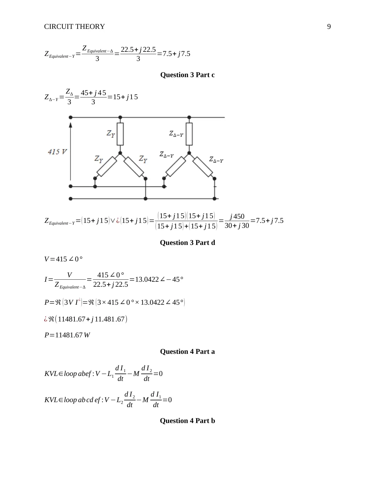
ZY =15+ j 15
Z∆=45+ j 4 5
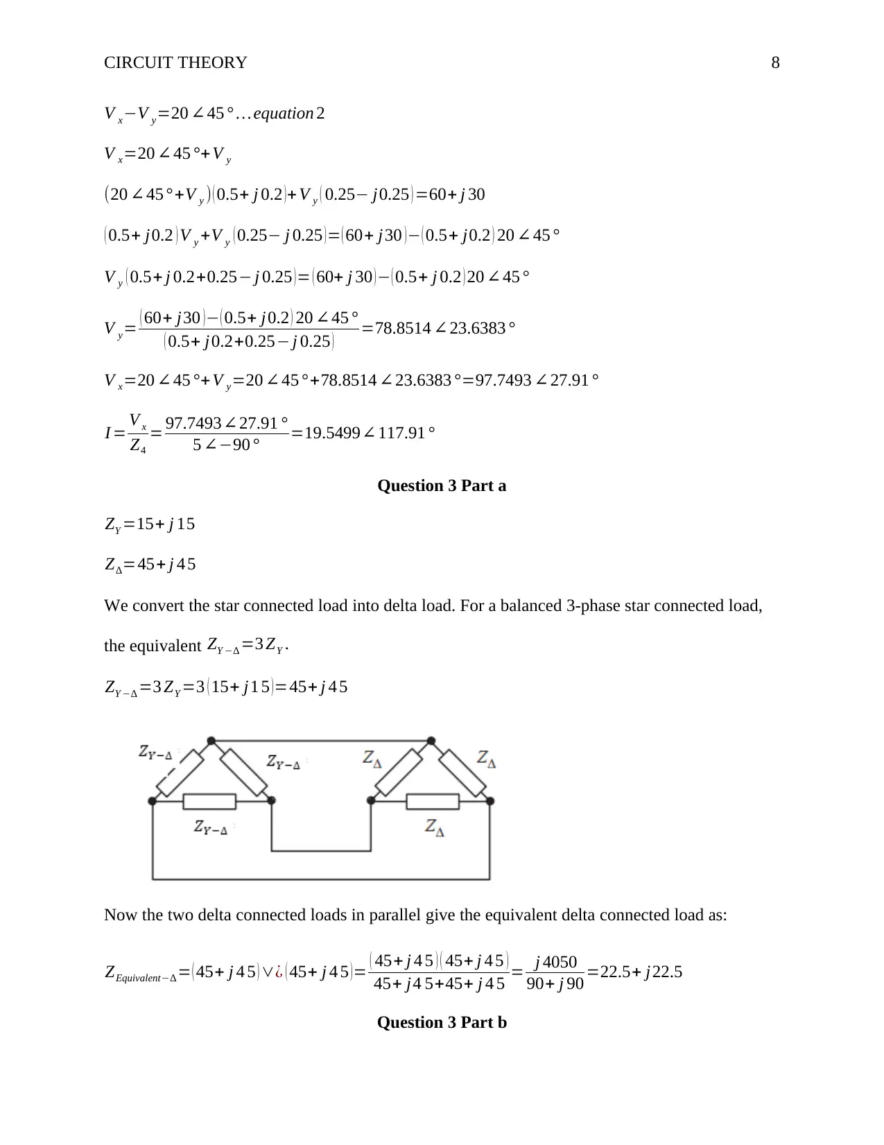
We convert the star connected load into delta load. For a balanced 3-phase star connected load,
the equivalent ZY −∆ =3 ZY .
ZY −∆ =3 ZY =3 ( 15+ j1 5 ) =45+ j 4 5
Now the two delta connected loads in parallel give the equivalent delta connected load as:
ZEquivalent−∆ = ( 45+ j 4 5 ) ∨¿ ( 45+ j 4 5 ) = ( 45+ j 4 5 ) ( 45+ j 4 5 )
45+ j4 5+45+ j 4 5 = j 4050
90+ j 90 =22.5+ j22.5
Question 3 Part b
CIRCUIT THEORY 9
ZEquivalent−Y = Z Equivalent−∆
3 = 22.5+ j 22.5
3 =7.5+ j7.5
Question 3 Part c
Z∆−Y = Z∆
3 = 45+ j 4 5
3 =15+ j1 5
ZEquivalent−Y = ( 15+ j1 5 ) ∨¿ ( 15+ j1 5 ) = ( 15+ j1 5 ) ( 15+ j1 5 )
( 15+ j1 5 ) + ( 15+ j1 5 ) = j 450
30+ j 30 =7.5+ j 7.5
Question 3 Part d
V =415 ∠ 0 °
I = V
Z Equivalent−∆
= 415 ∠ 0 °
22.5+ j 22.5 =13.0422∠−45°
P=ℜ ( 3V I¿ )=ℜ ( 3× 415 ∠0 °× 13.0422∠ 45° )
¿ ℜ(11481.67+ j 11.481.67)
P=11481.67 W
Question 4 Part a
KVL∈loop abef : V −L1
d I1
dt −M d I 2
dt =0
KVL∈loop ab cd ef :V −L2
d I2
dt −M d I1
dt =0
Question 4 Part b
⊘ This is a preview!⊘
Do you want full access?
Subscribe today to unlock all pages.

Trusted by 1+ million students worldwide
CIRCUIT THEORY 10
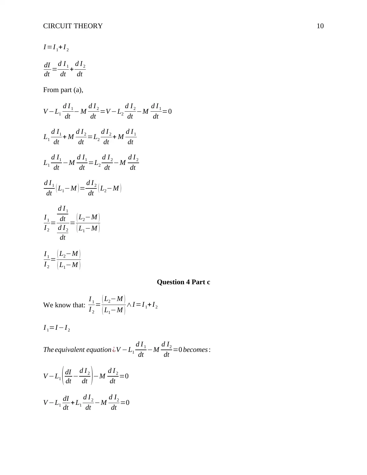
I =I1+ I2
dI
dt =d I1
dt + d I 2
dt
From part (a),
V −L1
d I 1
dt − M d I 2
dt =V −L2
d I2
dt −M d I 1
dt =0
L1
d I1
dt + M d I 2
dt =L2
d I2
dt + M d I 1
dt
L1
d I1
dt −M d I1
dt =L2
d I 2
dt −M d I2
dt
d I1
dt ( L1−M ) = d I 2
dt ( L2−M )
I1
I2
=
d I1
dt
d I2
dt
= ( L2−M )
( L1−M )
I1
I2
= ( L2−M )
( L1−M )
Question 4 Part c
We know that: I 1
I 2
= ( L2−M )
( L1−M ) ∧I =I 1+ I2
I 1=I −I2
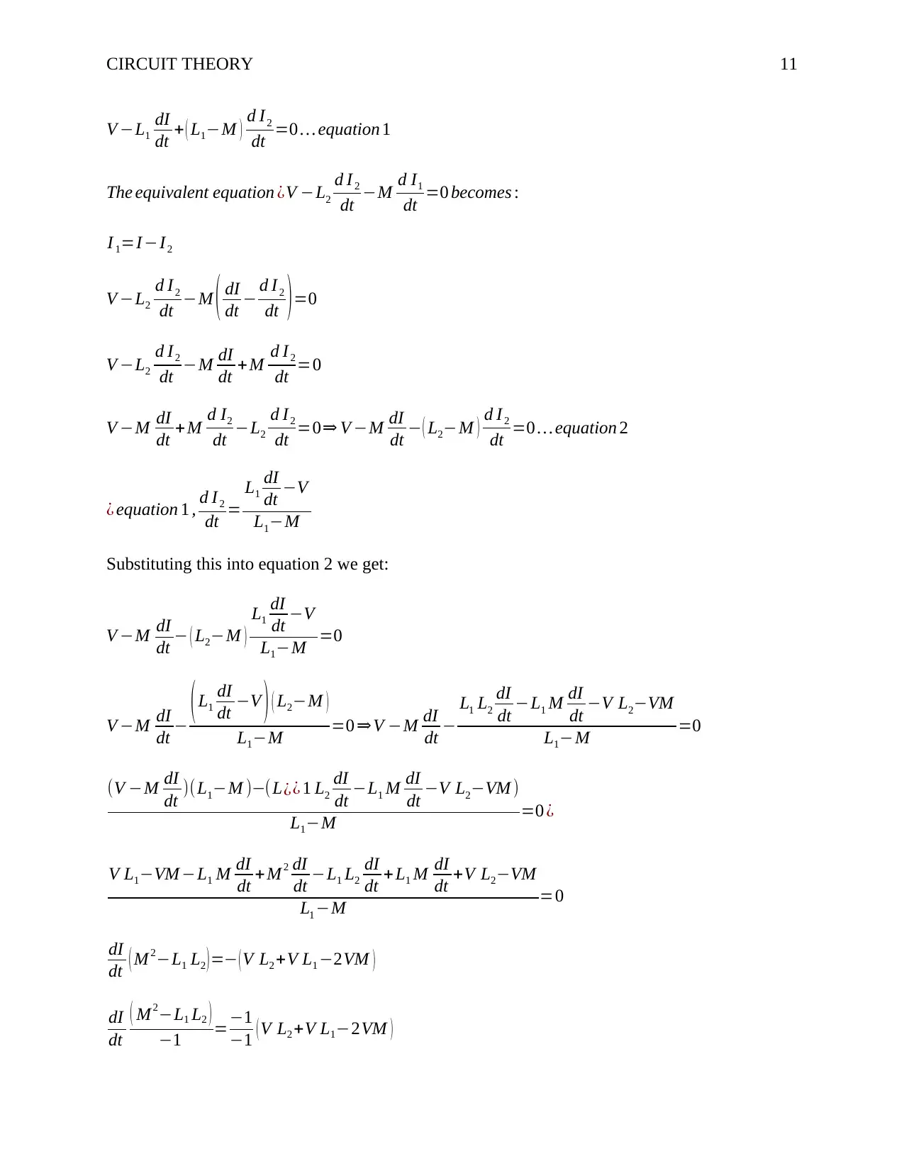
The equivalent equation ¿V −L1
d I 1
dt −M d I2
dt =0 becomes :
V −L1 ( dI
dt − d I2
dt )−M d I 2
dt =0
V −L1
dI
dt +L1
d I2
dt −M d I2
dt =0
Paraphrase This Document
Need a fresh take? Get an instant paraphrase of this document with our AI Paraphraser
CIRCUIT THEORY 11
V −L1
dI
dt + ( L1−M ) d I2
dt =0 … equation 1
The equivalent equation ¿V −L2
d I 2
dt −M d I1
dt =0 becomes :
I 1=I −I2
V −L2
d I2
dt −M ( dI
dt − d I 2
dt ) =0
V −L2
d I2
dt −M dI
dt +M d I 2
dt =0
V −M dI
dt +M d I2
dt −L2
d I2
dt =0⇒ V −M dI
dt − ( L2−M ) d I2
dt =0 … equation 2
¿ equation 1 , d I 2
dt =
L1
dI
dt −V
L1−M
Substituting this into equation 2 we get:
V −M dI
dt − ( L2−M )
L1
dI
dt −V
L1−M =0
V −M dI
dt − (L1
dI
dt −V ) ( L2−M )
L1−M =0 ⇒V −M dI
dt −
L1 L2
dI
dt −L1 M dI
dt −V L2−VM
L1−M =0
(V −M dI
dt )(L1−M )−(L¿¿ 1 L2
dI
dt −L1 M dI
dt −V L2−VM )
L1−M =0 ¿
V L1−VM −L1 M dI
dt + M 2 dI
dt −L1 L2
dI
dt + L1 M dI
dt +V L2−VM
L1 −M =0
dI
dt ( M 2−L1 L2 )=− (V L2 +V L1 −2VM )
dI
dt
( M2−L1 L2 )
−1 =−1
−1 ( V L2 +V L1−2VM )
CIRCUIT THEORY 12
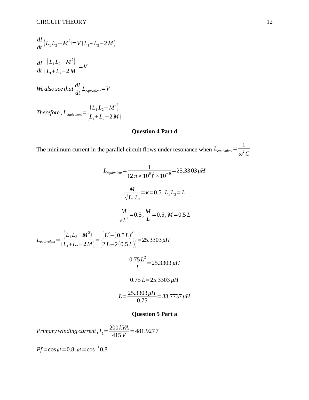
dI
dt ( L1 L2 −M 2
)=V ( L1+ L2−2 M )
dI
dt
( L1 L2−M 2 )
( L1 +L2−2 M ) =V
We also see that dI
dt Lequivalent =V
Therefore , Lequivalent = ( L1 L2−M 2 )
( L1 + L2−2 M )
Question 4 Part d
The minimum current in the parallel circuit flows under resonance when Lequivalent = 1
ω2 C
Lequivalent = 1
(2 π × 106 )2 ×10−9 =25.33 03 μH
M
√L1 L2
=k=0.5 , L1 L2= L
M
√L2 =0.5 , M
L =0.5 , M=0.5 L
Lequivalent = ( L1 L2−M 2 )
( L1+L2 −2 M ) = ( L2−( 0.5 L)2 )
( 2 L−2(0.5 L) ) =25.3303 μH
0.75 L2
L =25.3303 μH
0.75 L=25.3303 μH
L= 25.3303 μH
0.75 =33.7737 μH
Question 5 Part a
Primary winding current , I1= 200 kVA
415 V =481.927 7
Pf =cos ∅ =0.8 ,∅ =cos−1 0.8
dI
dt ( L1 L2 −M 2
)=V ( L1+ L2−2 M )
dI
dt
( L1 L2−M 2 )
( L1 +L2−2 M ) =V
We also see that dI
dt Lequivalent =V
Therefore , Lequivalent = ( L1 L2−M 2 )
( L1 + L2−2 M )
Question 4 Part d
The minimum current in the parallel circuit flows under resonance when Lequivalent = 1
ω2 C
Lequivalent = 1
(2 π × 106 )2 ×10−9 =25.33 03 μH
M
√L1 L2
=k=0.5 , L1 L2= L
M
√L2 =0.5 , M
L =0.5 , M=0.5 L
Lequivalent = ( L1 L2−M 2 )
( L1+L2 −2 M ) = ( L2−( 0.5 L)2 )
( 2 L−2(0.5 L) ) =25.3303 μH
0.75 L2
L =25.3303 μH
0.75 L=25.3303 μH
L= 25.3303 μH
0.75 =33.7737 μH
Question 5 Part a
Primary winding current , I1= 200 kVA
415 V =481.927 7
Pf =cos ∅ =0.8 ,∅ =cos−1 0.8
⊘ This is a preview!⊘
Do you want full access?
Subscribe today to unlock all pages.

Trusted by 1+ million students worldwide
1 out of 13
Related Documents
Your All-in-One AI-Powered Toolkit for Academic Success.
+13062052269
info@desklib.com
Available 24*7 on WhatsApp / Email
![[object Object]](/_next/static/media/star-bottom.7253800d.svg)
Unlock your academic potential
Copyright © 2020–2026 A2Z Services. All Rights Reserved. Developed and managed by ZUCOL.


