Implementation of MPLS VPN Network with Cisco 2811 Routers Report
VerifiedAdded on 2019/09/20
|9
|2065
|272
Report
AI Summary
This report provides a detailed overview of implementing an MPLS VPN network across multiple office locations (LON, PAR, US) using Cisco 2811 routers. The report begins with an introduction to MPLS VPN technology, its advantages, and the Cisco 2811 router's capabilities. It then outlines the network implementation, including the connections between the three offices, the roles of CE and PE routers, and the configuration steps required. The report emphasizes the use of MPLS VLN for quality of service and stability. It covers key aspects such as establishing connections between PE routers using MP-BGP, PE to CE link implementation using OSPF, and the overall methodology. The report concludes by highlighting the benefits of MPLS VPN, such as secure communication and efficient bandwidth utilization. References to relevant sources are also included.

Qwertyuiolkjhgfdazxcvbnmk
dchgsjjshgysuujhnbsjichgxhk
cnbxiikcjnxjjicoxjnxjkjdvdhvj
djvsjfuhdnvkjdnvjndvkjbdkjv
biudhgausjdnlkasndiajduah
wdiuahduudkjaschuoshcuias
hiuchsaiucuasjbcuabcujadsh
cuiagsdyiawodihsuchsiugfcjf
agfiyuagfiygafiygaiyfgaiyfgiy
agfiagfiagifugaiufgiaufgiaugfi
uafiugfiuagfiuaegfiugaefiuco
18090130957655
[Type the document subtitle]
[Pick the date]
Paraphrase This Document
Need a fresh take? Get an instant paraphrase of this document with our AI Paraphraser
Table of Contents
Introduction...........................................................................................................................................2
MPLS VPN and CISCO 2811....................................................................................................................3
Network Implementation......................................................................................................................4
Connections Implemented....................................................................................................................4
Customers edge (CE) router and Customers(C) router..........................................................................5
Providers(P) core router and Providers edge(PE) router.......................................................................5
Configuration of Routers.......................................................................................................................6
Establishing a Connection between PE Routers....................................................................................6
PE to CE Link Implementation...............................................................................................................6
Implementation and Methodology.......................................................................................................7
Conclusion.............................................................................................................................................7
References.............................................................................................................................................9
Introduction
The Following Report is an overview of the establishing a network between the offices in
various locations. Each place has its own working and its importance. They also must have
some privacy since there will be some managerial information transfers for the company. So
we have to provide the networking based on the requirement. The proposed Method in this
type is MPLS VLN .This Method is used since it is quality of service and stability compared
to other WAN networks is high. Using MPLS, the carrier use WAN routing protocol. This
makes MPLS operationally easier than controlling a large routed network. This means, that
companies can reduce the man power on WAN. MPLS is an Protocol technology developed
by IETF for the betterment of traditional IP routing technique. MPLS is a technique used by
network providers to give a better and single network architecture for real-time traffic in
voice and video.
MPLS VPN and CISCO 2811
Multiprotocol Label Switching (MPLS) provides the technique to perform label
switching, which is a unique method for dynamic performance packet forwarding. MPLS
and VPNs gives the first wider discussion particular to Cisco MPLS architecture.
Multiprotocol Label Switching(MPLS) and Virtual Private Networks(VPN) has a major
application using MPLS theory and configuration, network design issues.
In this type of network we are using MPLS VLN Method i.e. Multiprotocol Label
Switching has become a important technology in Internet Protocol technique for network
providers and places that prefer to avail remote connectivity. Enterprises are focusing
towards network providers which provide MPLS VPN. It has large number of users due
to the certain advantages over other VPN technologies . There are many innovative
features possessed by MPLS VPN, like VoIP by CoS, scalable bandwidth, voice and data
on a single channel through various sources, nowadays MPLS VPN has become the
updated technology in IP technology. We are using CISCO 2811 which provides Wire-
speed performance for current services such as security and audio, and advanced services
to many T1/E1/DSL WAN rates it also Support for majority of existing AIMs, NMs,
WICs, VWICs, and VICs
⊘ This is a preview!⊘
Do you want full access?
Subscribe today to unlock all pages.
Trusted by 1+ million students worldwide
Network Implementation
The Network comprises a connection between three offices in three different places
namely, LON (head office), PAR and US and each place has its own working. The LON
offices takes care of the Management and finance sectors.PAR offices has a HR team and a
IT team Working and finally the production Dept is in US.
The LON office is directly connected with the fast Ethernet since it takes care of the
financial and management side. PAR office is also connected with the core MPLS, the
connection from PAR to LON exists through this MPLS VLN mesh. All the three Offices
are connected to a central hub known as MPLS VLN .The link between LON and PAR
are producted by implementing IPSec protocol. The production house in US does not have
a access to LON or PAR offices because there must a privacy in managerial functions.
When the packet goes to the MPLS algorithm, LSR gets the packet and
implement label the MPLS label to the packet and given to the next hop via the Label
Switch Path. When the packet reaches the next LSR, it switch the incoming label with the
outgoing label and gives the packet. When the LSR gets the packet, it slips off the
packet label and forwards it to the final router. All the LSRs present in the MPLS network
have a separate Interior Gateway Protocol (IGB) which is running throughout the network.
To compromise the distribution task, adjacent LSRs must agree on the label that is used
for each IGP prefix.
Connections Implemented
MPLS VLN Core is the mesh from where each and every offices is connected using
Ethernet in each office there are several connections based on the requirement. In LON
office the finance side has about 30 users and management side comprises 20 users.
Similarly in PAR office there are 20 users in IT side and 20 users in HR side. In US there
are about 100 users.
There are two types of routers in the provider network, they are Provider’s Edge
and Provider’s routers. The Provider Edge router is connected to the Customer’s Edge
router of the customer networks. Both Provider Edge and Provider routers should run in
MPLS so that they can provide labels to each other and forward packets to random routers.
Paraphrase This Document
Need a fresh take? Get an instant paraphrase of this document with our AI Paraphraser
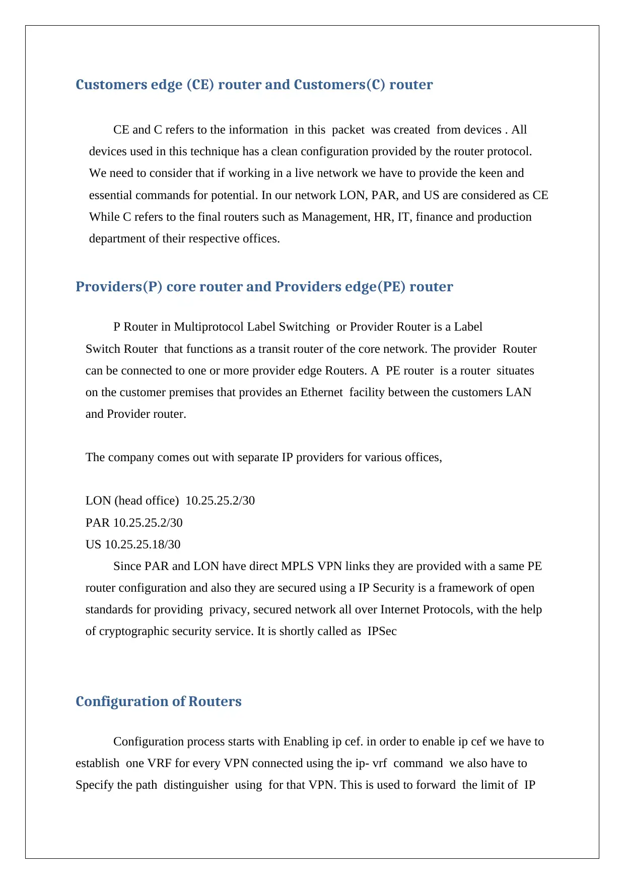
Customers edge (CE) router and Customers(C) router
CE and C refers to the information in this packet was created from devices . All
devices used in this technique has a clean configuration provided by the router protocol.
We need to consider that if working in a live network we have to provide the keen and
essential commands for potential. In our network LON, PAR, and US are considered as CE
While C refers to the final routers such as Management, HR, IT, finance and production
department of their respective offices.
Providers(P) core router and Providers edge(PE) router
P Router in Multiprotocol Label Switching or Provider Router is a Label
Switch Router that functions as a transit router of the core network. The provider Router
can be connected to one or more provider edge Routers. A PE router is a router situates
on the customer premises that provides an Ethernet facility between the customers LAN
and Provider router.
The company comes out with separate IP providers for various offices,
LON (head office) 10.25.25.2/30
PAR 10.25.25.2/30
US 10.25.25.18/30
Since PAR and LON have direct MPLS VPN links they are provided with a same PE
router configuration and also they are secured using a IP Security is a framework of open
standards for providing privacy, secured network all over Internet Protocols, with the help
of cryptographic security service. It is shortly called as IPSec
Configuration of Routers
Configuration process starts with Enabling ip cef. in order to enable ip cef we have to
establish one VRF for every VPN connected using the ip- vrf command we also have to
Specify the path distinguisher using for that VPN. This is used to forward the limit of IP
address so that you can locate which VPN it belongs . Then we have to configure the
import and export properties for the MP-BGP extended networks. These are used for
reducing the import and export process. Next Step is to Configure the forwarding details for
the interfaces using the ip- vrf forwarding command and remember to set up the IP address
after doing this. On comparing the PE-CE routing protocol we are using, we can configure
static routes or routing protocols (RIP, Open Shortest Path First [OSPF], or BGP) between
PE and CE.
For the establishment of MPLS VPN, routers must have following hardware and
software requirements to support the MPLS VPNs. Router that support MPLS topology
Cisco IOS. Software that provides with VPN features and a 64 MB of flash with at least 192
DRAM. For CE routers, any router that can be able to give routing information with its PE
router.
Establishing a Connection between PE Routers
Setting up the MP-BGP between the PE routers. There are several steps to configure
BGP, such as using the some confederation methods. The direct neighbour configuration—
is the simplest and the low scalable. Declare the different neighbours for connection. Provide
a address-family ipv4- vrf command for all VPN present at this PE path then we have to
Distribute the static routing, RIP, or OSPF information along the routers of PE so that they
can be able to communicate with their respective customer edge routers. Then Provide
address family vpn-v4 mode, and Activate the neighbours specify extended group must be
used in this process.
PE to CE Link Implementation
In this Method of networking ,service providers to configure Open Shortest Path First
between provider edge and customer edge devices in an MPLS VPN network. This has
increased flexibility when devices exchange routing information among sites because a
separate router ID for each interface or sub interface is provided and configured on a PE
⊘ This is a preview!⊘
Do you want full access?
Subscribe today to unlock all pages.
Trusted by 1+ million students worldwide
device attached to multiple CE devices within a VPN.The first option is to run static routing
between both PE- and CE-routers routing. An Important technique that is established in
OSPF is Interior Gateway Protocols (IGP). In an MPLS, OSPF is not used to route customer
traffic. It is only used to provide routing for the internal provider network so that labels can
be generated. LDP is used to advertise these labels to neighbouring label-switched routers
hence IGP provides a keen role in making the OSPF to communicate
Implementation and Methodology
An MPLS network is a keen network which supports MPLS enabled routers called
Label Switch Routers . The network has a core LSR with an edge LSR which applies labels
to packets. The working is implemented by Routing tables of the different LSRs are
calculated along with an Interior Gateway Protocol . A link state protocol, such as Open
Shortest Path First is required if we have networking to deploy MPLS TE.
This setup provides the contact between multi protocol Border Gateway Protocol
running between Provider Edge routers and Open Shortest Path First protocol working
inside a Virtual Private Network implemented with MPLS VPN technology. The OSPF
routes gets one PE-router can be propagated across the MPLS core system and distributed
back into OSPF at other site as external OSPF routers.
Conclusion
Hence through this techniques and implementation methods, we can able to provide a
communication with offices in various location with a secured manner. It provides effective
methods of technologies and protocols to solve the most pressing network-design problems.
It helps to determine the importance in providing MPLS VPN in the traditional IP-v4
network. MPLS VPN network provides significant bandwidth between providers network
and customer site to accomplish the requirements of VoIP. Because of these facilities like
Paraphrase This Document
Need a fresh take? Get an instant paraphrase of this document with our AI Paraphraser
variable bandwidth, convergence of data’s in a single infrastructure, MPLS VPN has
become most wanted technology in IP technology.
References
become most wanted technology in IP technology.
References
Services, P., Routers, B., Products, E. and Routers, C.. 2018. Cisco 2811 Integrated
Services Router. [online] Cisco.. [ONLINE] Available
at: https://www.cisco.com/c/en/us/products/routers/2811-integrated-services-router-
isr/index.html. [Accessed 3 September 2018].
Gurung, S. 2018. IMPLEMENTATION OF MPLS VPN. [ONLINE] Available
at: https://www.theseus.fi/bitstream/handle/10024/103442/Sanjib
%20Gurungthesis.pdf?sequence=1. [Accessed 3 September 2018].
Ijettjournal. 2018. A Design Analysis of MPLS VPN Core Architecture and Network
Downtime Impact. [ONLINE] Available
at: http://ijettjournal.org/2016/volume-33/number-3/IJETT-V33P224.pdf. [Accessed 3
September 2018].
Omicsonline.org. (2018). 2018. Architecture for MPLS L3 VPN Deployment in
Service Provider Network. [ONLINE] Available at: https://www.omicsonline.org/open-
access/architecture-for-mpls-l3-vpn-deployment-in-service-provider-network-2167-
0919-1000152.pdf. [Accessed 3 September 2018].
Racf.bnl.gov. (2018).. 2018. Using OSPF in an MPLS VPN Environment. [ONLINE]
Available at: https://www.racf.bnl.gov/Facility/TechnologyMeeting/Archive/06-30-04-
CISCO/Using-OSPF-in-MPLS-VPN-Environment.pdf. [Accessed 3 September 2018].
⊘ This is a preview!⊘
Do you want full access?
Subscribe today to unlock all pages.
Trusted by 1+ million students worldwide
1 out of 9
Related Documents


Your All-in-One AI-Powered Toolkit for Academic Success.
+13062052269
info@desklib.com
Available 24*7 on WhatsApp / Email
![[object Object]](/_next/static/media/star-bottom.7253800d.svg)
Unlock your academic potential
Copyright © 2020–2026 A2Z Services. All Rights Reserved. Developed and managed by ZUCOL.