Network Design and Analysis Project: Cisco Simulation

Verified

Added on  2021/06/15

|15
|1542
|55
Project
AI Summary
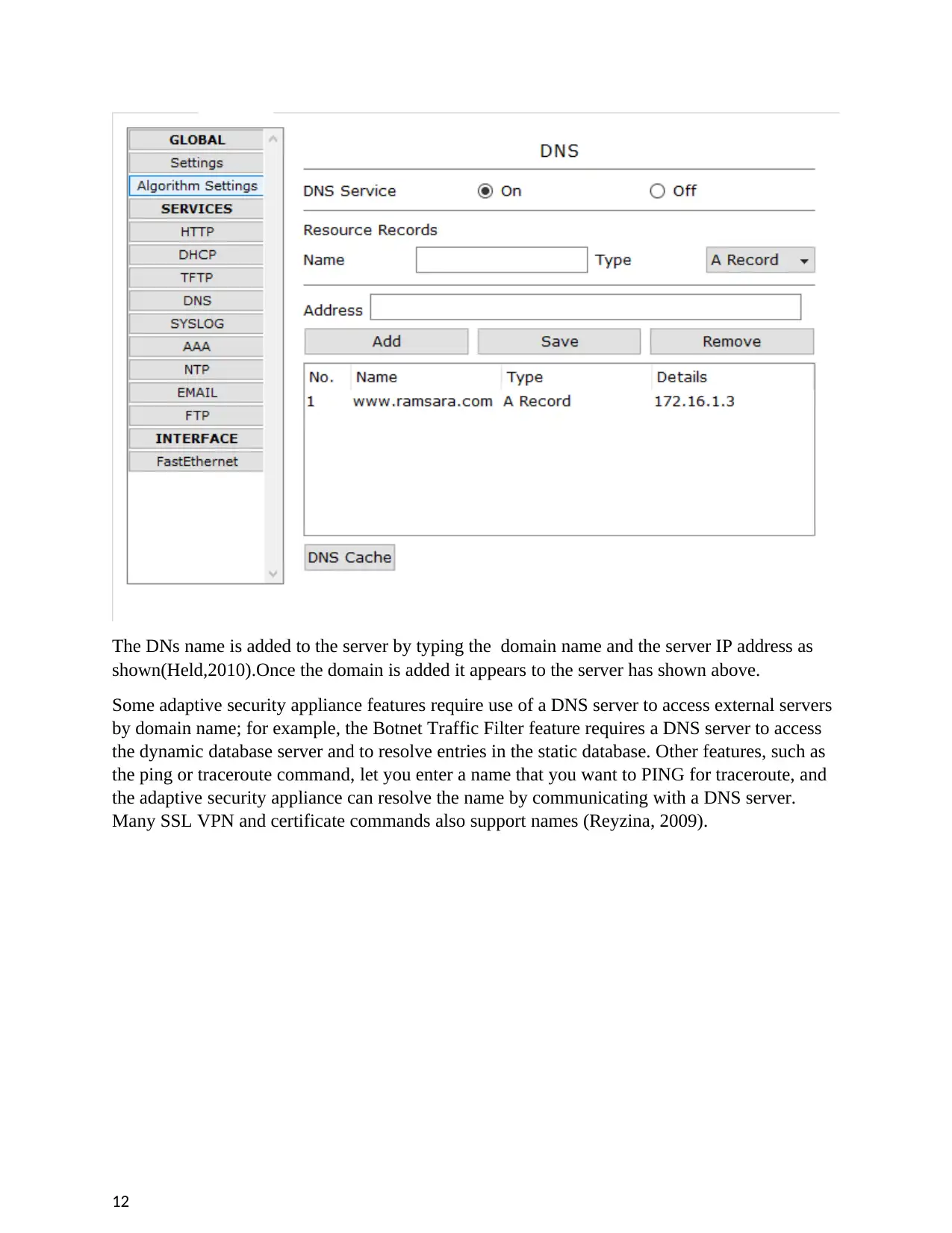
This project report details the design and analysis of a network using Cisco Packet Tracer simulation software. The project begins with setting up a network topology consisting of routers, servers, and PCs, each assigned unique IP addresses and subnet masks. Configuration of routers involves defining network IDs and subnet masks, while the project also tests network connectivity through pinging various network components, including the PC's own interface, the local router, an outward router, and a server. The report further explores the configuration of essential network services, including DHCP for dynamic IP address assignment, a web server requiring DNS configuration for name resolution, and a DNS server setup for domain name resolution. Additionally, the project covers firewall implementation to filter data and control network access. The report concludes with a list of references.
Document Page
NETWORK DESIGN AND ANALYSIS.
Name:
Reg No.
Date Of Submission.
1
tabler-icon-diamond-filled.svg

Paraphrase This Document

Need a fresh take? Get an instant paraphrase of this document with our AI Paraphraser
Document Page
Executive Summary
With advanced steps and improvement of technology mainly in networking has enhance high speed in
communication. As part of this cisco as aimed to improve the implementation and innovation of new
technologies that enhances security between the network devices. More so it is promoting learning
through release of simulation software that allows learners to configure networks and test them.The
following is the implementation of some of the features that are promoted by cisco optimization to
unlock the road of network development.
2
Document Page
1 Task 1 - Setting up a Network
Network design configuring (Janitor,2010)
The figure above shows the diagram outline of the network that was set up using cisco
simulation software. The diagram composes of two routers two servers and the two pc. Each
network device within the network is identified by a unique IP address. PC-PT is given the
following identification details ip 192.168.1.2 subnet =255.255.255.0 default
gateway=192.168.1.1.The subnet identifies the ip address of the pc with bitwise AND operation
within the network. In the other hand the default gateway is the route that is used by the
computer to communicate with the other computers in another network subnet.
The routers are also used to perform traffic redirection on the network. They divide the
network into subnetworks. Each ip router is set with a different address and subnet mask id .In
router 0 the network id is ip=99.99.99.1 subnet 255.255.255.252 and that of router one the
network ids are ip=99.99.99.2 subnet 255.255.255.0.The two servers are connected to the
network switches in which they communicate .They are given specific network ids which
uniquely identifies them within the network.
The following codes were used to configure the routers.
LINEPROTO-5-UPDOWN: Line protocol on Interface Serial0/0, changed state to up
3
Document Page
%LINEPROTO-5-UPDOWN: Line protocol on Interface Serial0/0, changed state to
down
%LINEPROTO-5-UPDOWN: Line protocol on Interface Serial0/0, changed state to up
%LINEPROTO-5-UPDOWN: Line protocol on Interface Serial0/0, changed state to
down
%LINEPROTO-5-UPDOWN: Line protocol on Interface Serial0/0, changed state to up
Router>enable
Router#configure terminal
Enter configuration commands, one per line. End with CNTL/Z.
Router(config)#interface Serial0/0
Router(config-if)#
Router#
%SYS-5-CONFIG_I: Configured from console by console
Router#
Router#
PINGING OF ROUTERS
3 Routing piece to self interface
4
tabler-icon-diamond-filled.svg

Paraphrase This Document

Need a fresh take? Get an instant paraphrase of this document with our AI Paraphraser
Document Page
When THE PC is pinged to its own network interface then it checks whether the network
components are correct or not.This also check whether the computer network software are
correct .The packets are received successfully by the PC in the network meaning that
hardware components of PC are correctly configured .
To the local router
When the pc is pinged to the local router the above results were successfully obtained. The pc
received responses from the router port as shown above. Also all the four packet were received
from the router meaning there was no loss of packets in the network during the process.
5
Document Page
To the local router interface
When the pc is pinged to the outward router the above results were successfully obtained. The
pc received responses from the router port as shown above. Also all the four packet were
received form the router there was no loss of packets in the network during pinging. The
received and obtained values are the same this means the packet lost equals to zero.
6
Document Page
To the server
The is configured using the ip address 172.16.1.3 and 172.16.1.4,Both of them have a common
gateway 176.2.1.1.There many servers which each have different types of settings .Each server
has different types of configuration(Moss,2010).
7
tabler-icon-diamond-filled.svg

Paraphrase This Document

Need a fresh take? Get an instant paraphrase of this document with our AI Paraphraser
Document Page
Using Trace route from client to server
Trace route is a configuration between the server and the client. The client request information
from the server and waits for the request to be responded to.
8
Document Page
Task 2 - Configuring Network Services
1 Configuring DHCP on the server
PCT-PT sends a request "DHCP Discovery" message that says that it request an ip address.
(Amato,2009)The DHCP servers answers with setup offers to the pc by "DHCP Offer" unicast
message. After that DHCP customer sends a communicate "DHCP Request" message to the
system with the "Exchange ID" of the main DHCP Server that send DHCP Offer. The other
DHCP servers comprehend that DHCP customer needs to utilize the DHCP server that has the
related "Exchange ID". In conclusion the DHCP server sends a unicast "DHCP
Acknowledgment" message to the DHCP customer that says the ip task is effectively done or it
send a deny informed named "DHCP-NACK"(Index,2013).
9
Document Page
To design a switch's dhcp, we should take after some fundamental guidance. For this design the
imperative point is communicated spaces. On the off chance that we have just a single
communicate area in our topology, at that point our work is more fundamental, else we should
get assistance from "imp-aide address" command. This order will help us to persuade the switch
and influence it to pass the communicate bundles.
2 Configuring a WEB server on dedicated machine
10
tabler-icon-diamond-filled.svg

Paraphrase This Document

Need a fresh take? Get an instant paraphrase of this document with our AI Paraphraser
Document Page
When the above request is typed on the web browser it returns the above error since it receives
no respond from the browser. This happens since no DNS name is added to server so that it can
respond to any requests (Networking, 2013).
3. Configuring a DNS Server on the server device
11
Document Page
The DNs name is added to the server by typing the domain name and the server IP address as
shown(Held,2010).Once the domain is added it appears to the server has shown above.
Some adaptive security appliance features require use of a DNS server to access external servers
by domain name; for example, the Botnet Traffic Filter feature requires a DNS server to access
the dynamic database server and to resolve entries in the static database. Other features, such as
the ping or traceroute command, let you enter a name that you want to PING for traceroute, and
the adaptive security appliance can resolve the name by communicating with a DNS server.
Many SSL VPN and certificate commands also support names (Reyzina, 2009).
12
chevron_up_icon
1 out of 15
circle_padding
hide_on_mobile
zoom_out_icon
[object Object]