Cisco Packet Tracer: TCP/IP Networking & Hierarchical Network Design
VerifiedAdded on 2023/06/11
|17
|1921
|277
Practical Assignment
AI Summary
This practical assignment focuses on simulating a hierarchical network model using Cisco Packet Tracer, demonstrating key networking concepts and configurations. The solution details the setup of a network topology with PCs, routers, and servers, utilizing private IP addresses for LANs and a WAN. It covers the configuration of PC, server, and router interfaces, along with IP routing to enable communication between networks. The assignment also includes configuring network services such as DHCP, a web server, DNS server, and network firewalls, illustrating how to implement these services within the simulated environment. Linux commands like ping and traceroute are used to test network connectivity and trace packet paths, while firewall configurations are implemented to block TCP traffic. This comprehensive simulation provides a hands-on understanding of network design and configuration using Cisco Packet Tracer. Desklib offers similar solved assignments for students.

Student Name: Student Number:
TCP/IP NETWORKING
Student Name
Institution
1
TCP/IP NETWORKING
Student Name
Institution
1
Paraphrase This Document
Need a fresh take? Get an instant paraphrase of this document with our AI Paraphraser
Student Name: Student Number:
Executive Summary
A good network design consist of a number of infrastructure which consist of network devices such as
routers, switches, hubs, transmission media, among others. A good design follows hierarchical model
that divides the entire network into three distinct layers (Welcher, 2015). These layers include the
access layer, distribution layer and the core layer. Each layer is characterized with the kind of the
operation it performs in the network. For a good network, it should be scalable, that is it devices can be
added freely without affecting the operations of the other parts of the network. Another feature of a
good network is security, easy to troubleshoot and monitor and the ability to communicate effectively
without hitches.
This report therefore involve the simulation of the hierarchical network design model using cisco packet
tracer which is a network simulation tool from cisco (SLATTERY, 2007). This assessment consist of two
parts of the practical assessment. The first part consist of a basic network setup using PCs, switches and
routers and the transmission media. The network Interfaces are also created and network Linux
commands such as ping and traceroute are used. The second part involves the configuration of various
network services such as DHCP, Web server, DNS server and network firewalls using cisco packet tracer.
Introduction
Following the given instructions in this assessment cisco packet tracer tool was used to simulate the
network and all the services needed in this report (Scire, 2015). A screenshot of every section is
provided as well as the execution of the Linux commands used in both task 1 and task 2 (Techopedia,
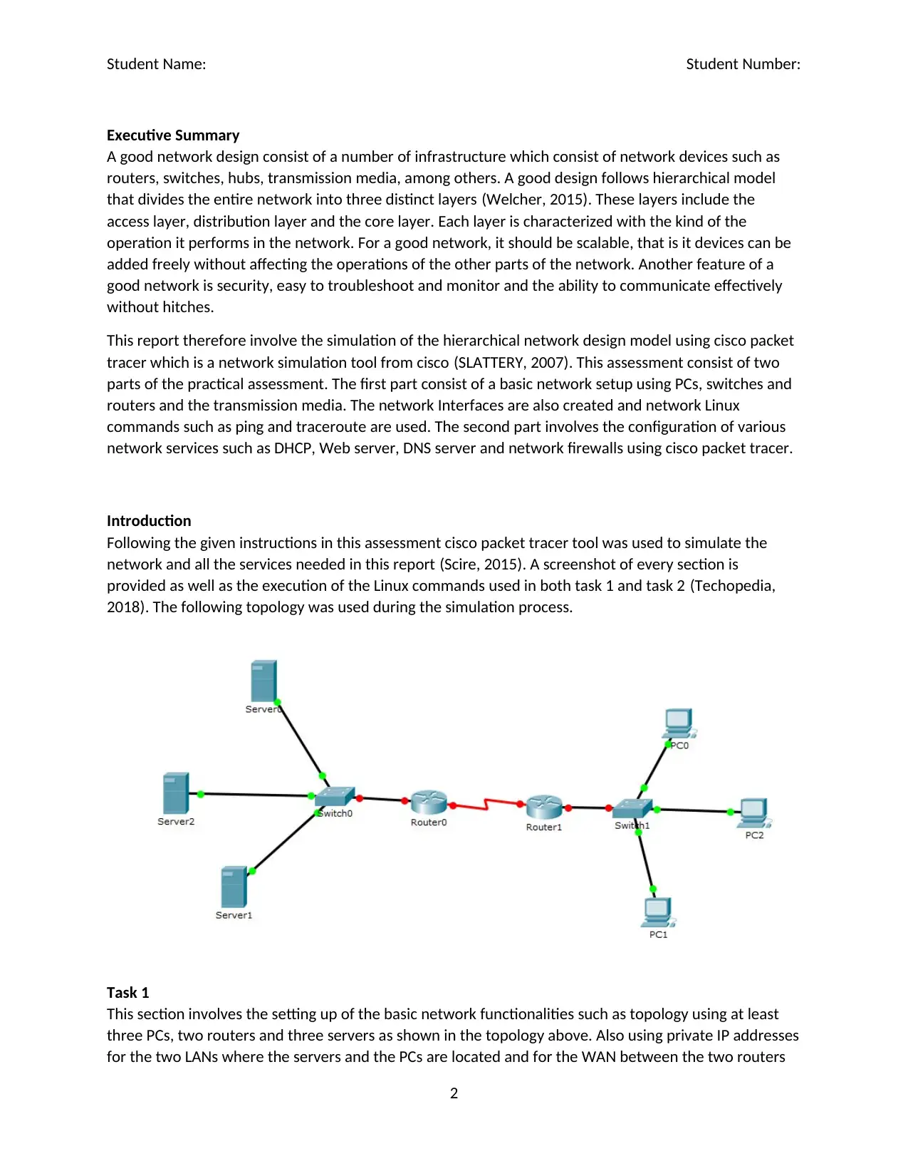
2018). The following topology was used during the simulation process.
Task 1
This section involves the setting up of the basic network functionalities such as topology using at least
three PCs, two routers and three servers as shown in the topology above. Also using private IP addresses
for the two LANs where the servers and the PCs are located and for the WAN between the two routers
2
Student Name: Student Number:
(Fisher, 2018). The IP address for the server network is 174.24.0.0 while that of the PCs network is
10.25.0.0 (Media, 2016). The IP address used to link the two networks that is for the WAN between the
two routers is 192.168.0.0.
Configuration of PCs, servers and routers interfaces
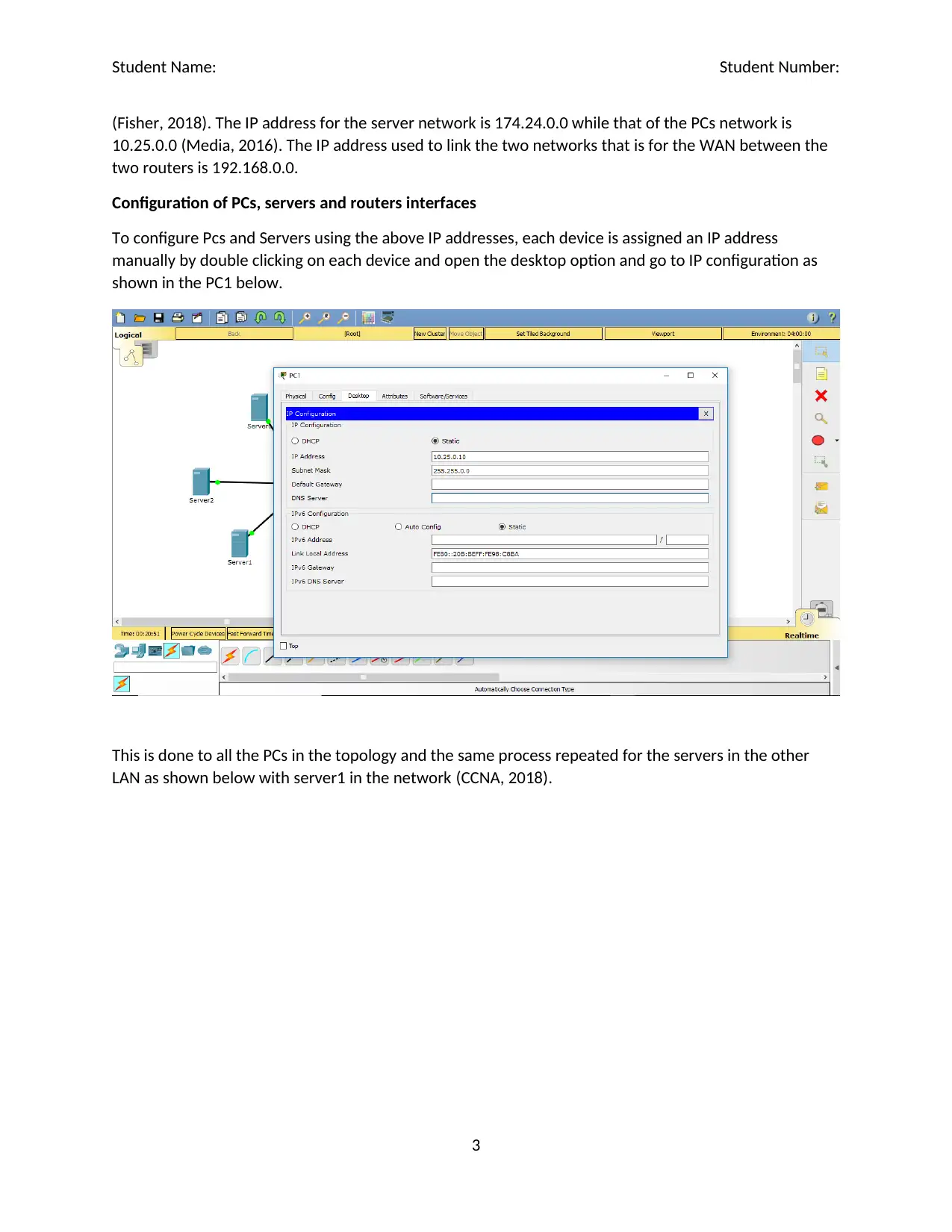
To configure Pcs and Servers using the above IP addresses, each device is assigned an IP address
manually by double clicking on each device and open the desktop option and go to IP configuration as
shown in the PC1 below.
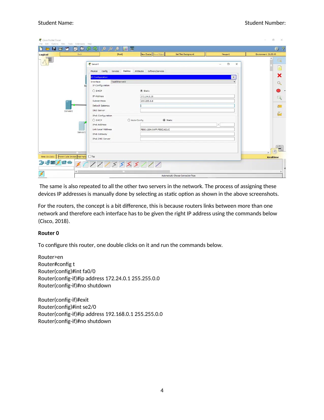
This is done to all the PCs in the topology and the same process repeated for the servers in the other
LAN as shown below with server1 in the network (CCNA, 2018).
3
⊘ This is a preview!⊘
Do you want full access?
Subscribe today to unlock all pages.

Trusted by 1+ million students worldwide
Student Name: Student Number:
The same is also repeated to all the other two servers in the network. The process of assigning these
devices IP addresses is manually done by selecting as static option as shown in the above screenshots.
For the routers, the concept is a bit difference, this is because routers links between more than one
network and therefore each interface has to be given the right IP address using the commands below
(Cisco, 2018).
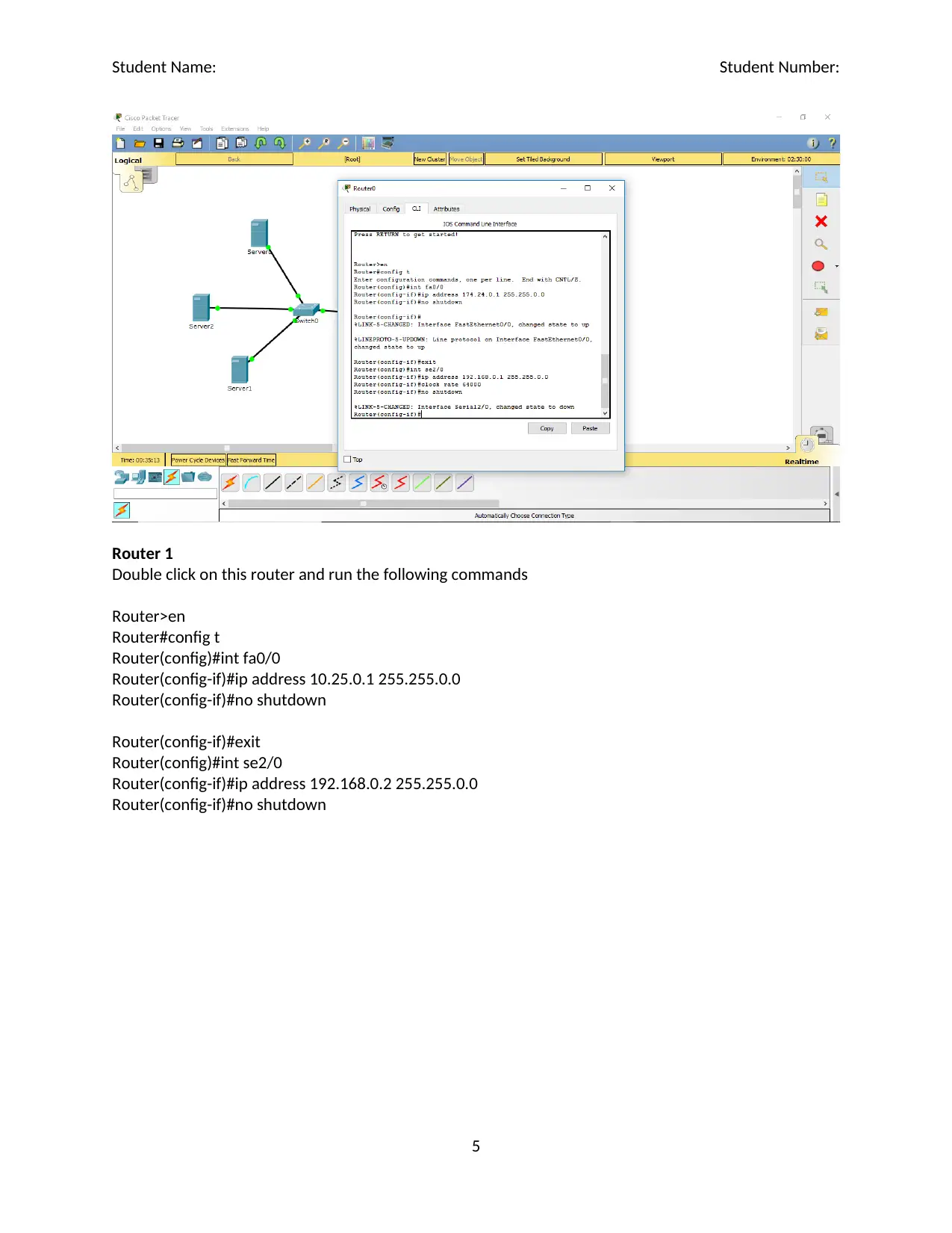
Router 0
To configure this router, one double clicks on it and run the commands below.
Router>en
Router#config t
Router(config)#int fa0/0
Router(config-if)#ip address 172.24.0.1 255.255.0.0
Router(config-if)#no shutdown
Router(config-if)#exit
Router(config)#int se2/0
Router(config-if)#ip address 192.168.0.1 255.255.0.0
Router(config-if)#no shutdown
4
Paraphrase This Document
Need a fresh take? Get an instant paraphrase of this document with our AI Paraphraser
Student Name: Student Number:
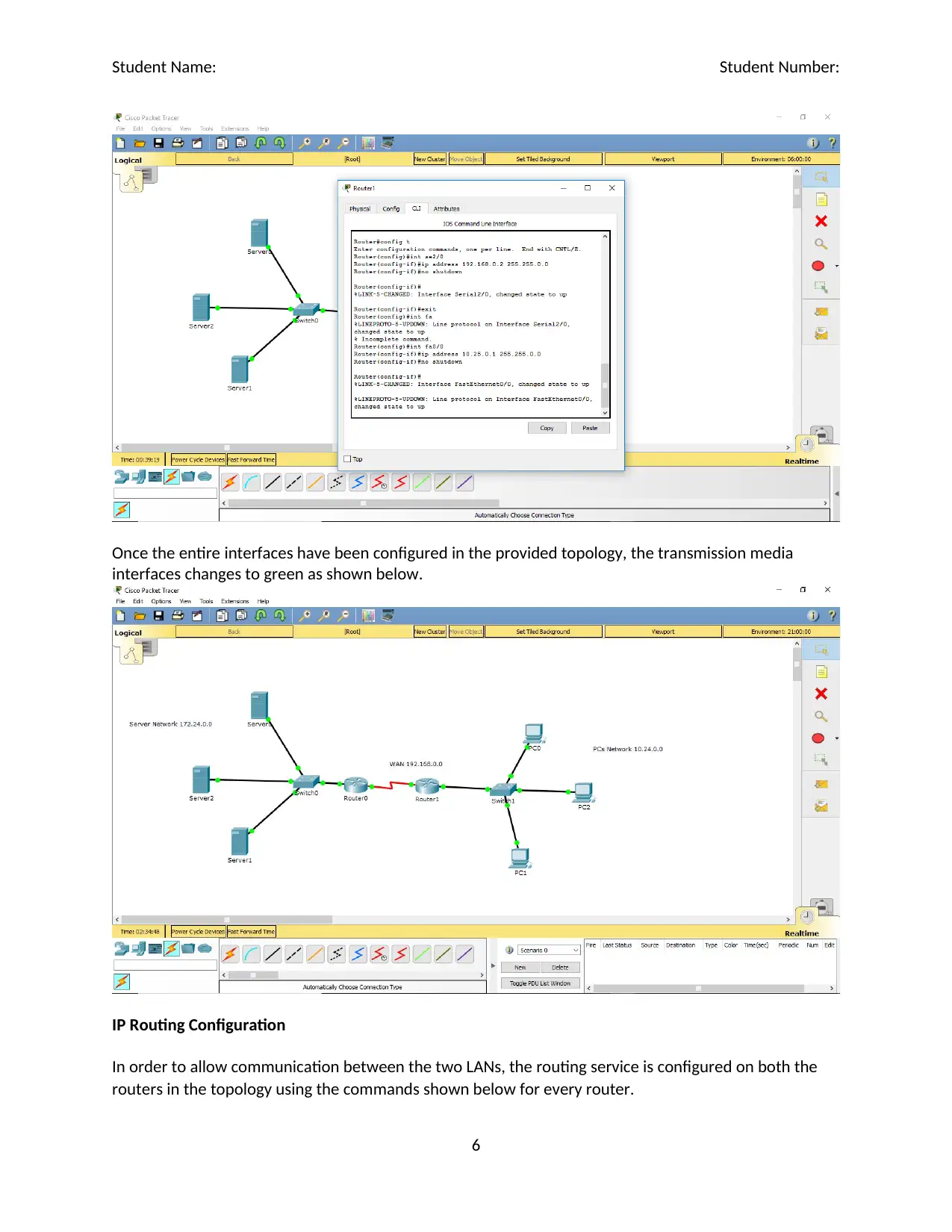
Router 1
Double click on this router and run the following commands
Router>en
Router#config t
Router(config)#int fa0/0
Router(config-if)#ip address 10.25.0.1 255.255.0.0
Router(config-if)#no shutdown
Router(config-if)#exit
Router(config)#int se2/0
Router(config-if)#ip address 192.168.0.2 255.255.0.0
Router(config-if)#no shutdown
5
Student Name: Student Number:
Once the entire interfaces have been configured in the provided topology, the transmission media
interfaces changes to green as shown below.
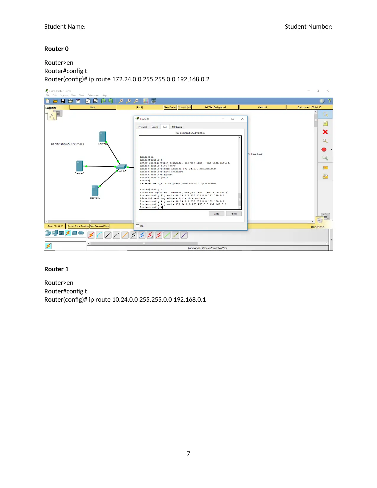
IP Routing Configuration
In order to allow communication between the two LANs, the routing service is configured on both the
routers in the topology using the commands shown below for every router.
6
⊘ This is a preview!⊘
Do you want full access?
Subscribe today to unlock all pages.

Trusted by 1+ million students worldwide
Student Name: Student Number:
Router 0
Router>en
Router#config t
Router(config)# ip route 172.24.0.0 255.255.0.0 192.168.0.2
Router 1
Router>en
Router#config t
Router(config)# ip route 10.24.0.0 255.255.0.0 192.168.0.1
7
Router 0
Router>en
Router#config t
Router(config)# ip route 172.24.0.0 255.255.0.0 192.168.0.2
Router 1
Router>en
Router#config t
Router(config)# ip route 10.24.0.0 255.255.0.0 192.168.0.1
7
Paraphrase This Document
Need a fresh take? Get an instant paraphrase of this document with our AI Paraphraser
Student Name: Student Number:
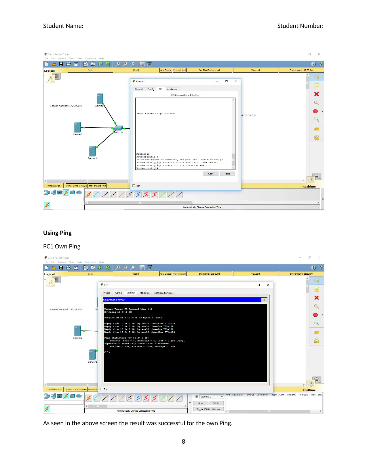
Using Ping
PC1 Own Ping
As seen in the above screen the result was successful for the own Ping.
8
Using Ping
PC1 Own Ping
As seen in the above screen the result was successful for the own Ping.
8
Student Name: Student Number:
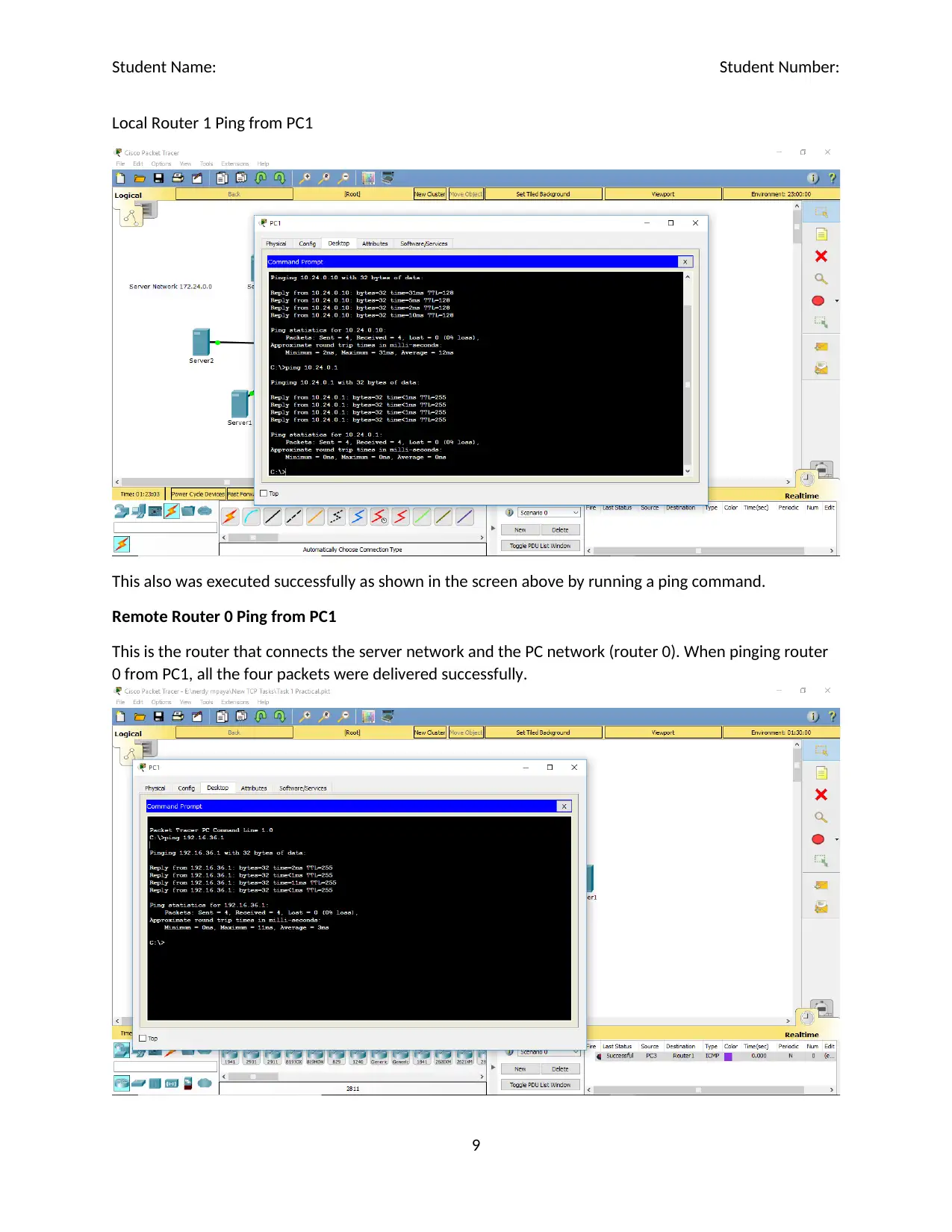
Local Router 1 Ping from PC1
This also was executed successfully as shown in the screen above by running a ping command.
Remote Router 0 Ping from PC1
This is the router that connects the server network and the PC network (router 0). When pinging router
0 from PC1, all the four packets were delivered successfully.
9
⊘ This is a preview!⊘
Do you want full access?
Subscribe today to unlock all pages.

Trusted by 1+ million students worldwide
Student Name: Student Number:
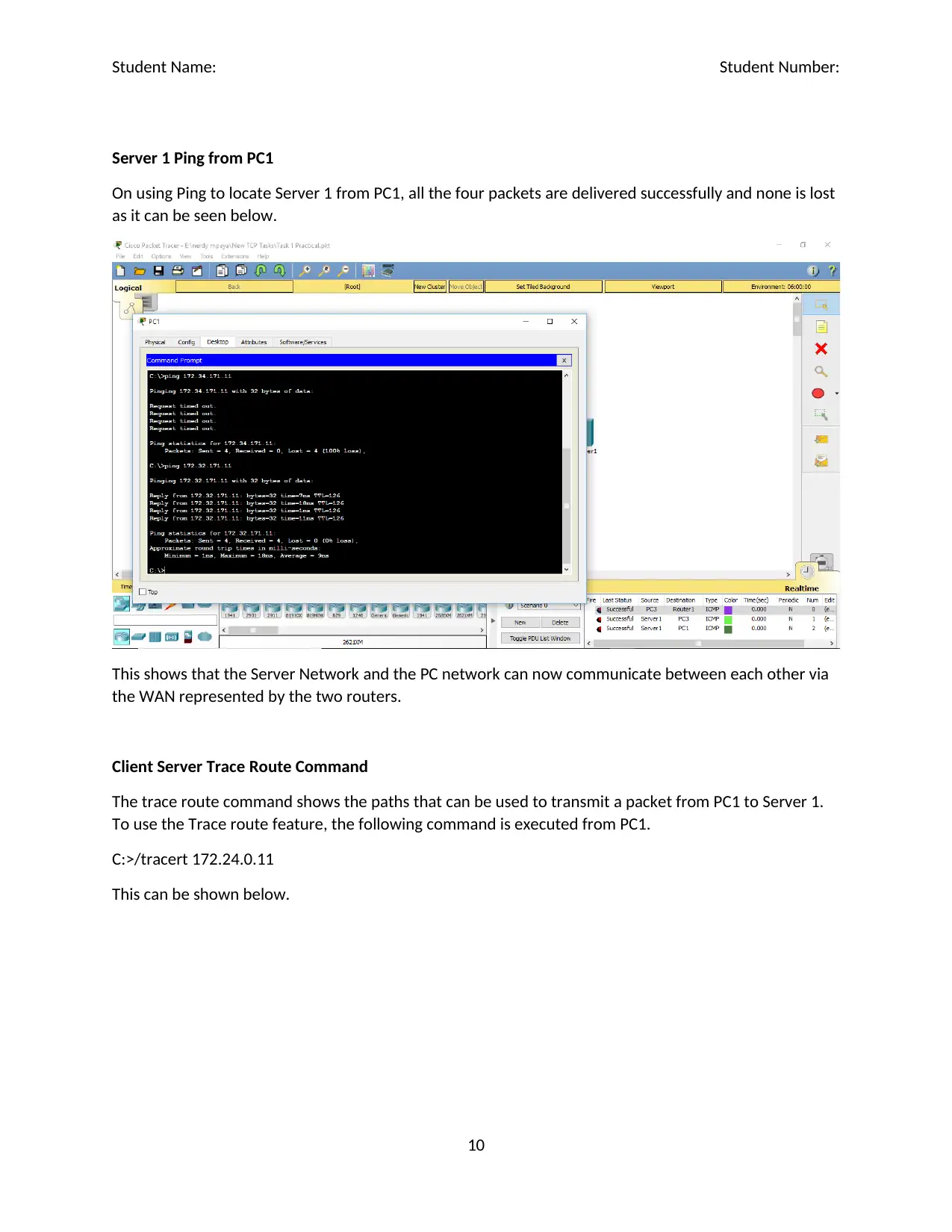
Server 1 Ping from PC1
On using Ping to locate Server 1 from PC1, all the four packets are delivered successfully and none is lost
as it can be seen below.
This shows that the Server Network and the PC network can now communicate between each other via
the WAN represented by the two routers.
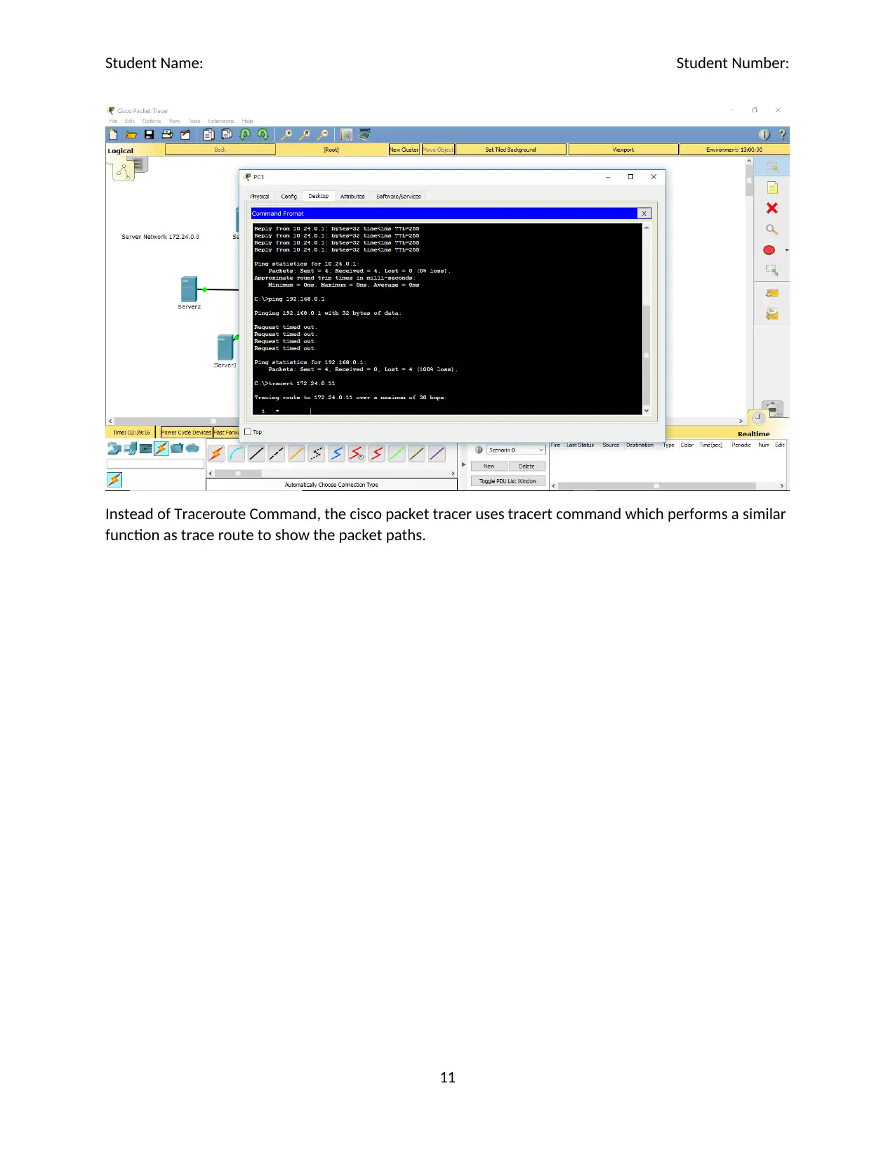
Client Server Trace Route Command
The trace route command shows the paths that can be used to transmit a packet from PC1 to Server 1.
To use the Trace route feature, the following command is executed from PC1.
C:>/tracert 172.24.0.11
This can be shown below.
10
Paraphrase This Document
Need a fresh take? Get an instant paraphrase of this document with our AI Paraphraser
Student Name: Student Number:
Instead of Traceroute Command, the cisco packet tracer uses tracert command which performs a similar
function as trace route to show the packet paths.
11
Instead of Traceroute Command, the cisco packet tracer uses tracert command which performs a similar
function as trace route to show the packet paths.
11
Student Name: Student Number:
Task 2
This task involved creating of various network services including DHCP, Web Server, DNS Server and the
Firewall for the same topology defined for this assessment.
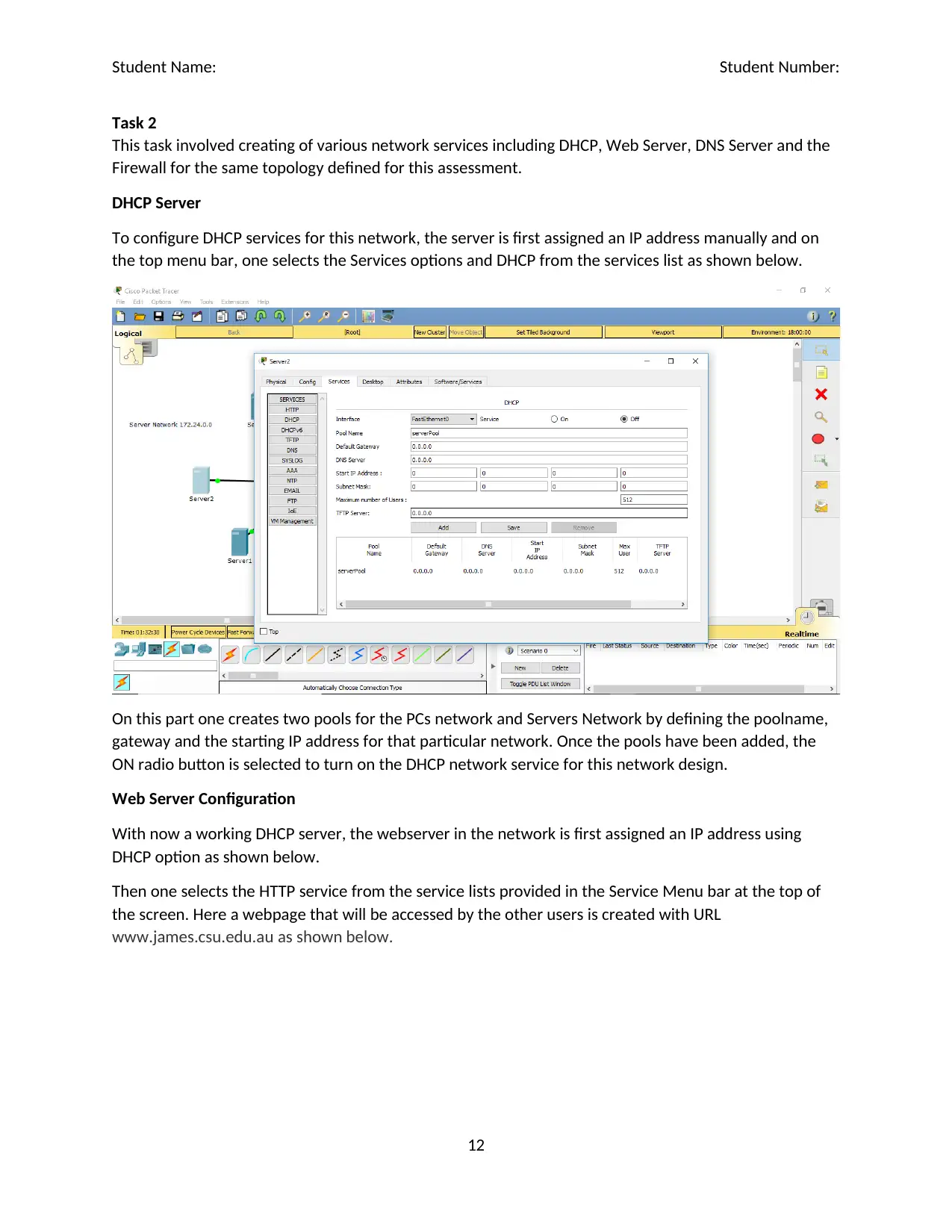
DHCP Server
To configure DHCP services for this network, the server is first assigned an IP address manually and on
the top menu bar, one selects the Services options and DHCP from the services list as shown below.
On this part one creates two pools for the PCs network and Servers Network by defining the poolname,
gateway and the starting IP address for that particular network. Once the pools have been added, the
ON radio button is selected to turn on the DHCP network service for this network design.
Web Server Configuration
With now a working DHCP server, the webserver in the network is first assigned an IP address using
DHCP option as shown below.
Then one selects the HTTP service from the service lists provided in the Service Menu bar at the top of
the screen. Here a webpage that will be accessed by the other users is created with URL
www.james.csu.edu.au as shown below.
12
⊘ This is a preview!⊘
Do you want full access?
Subscribe today to unlock all pages.

Trusted by 1+ million students worldwide
1 out of 17
Related Documents
Your All-in-One AI-Powered Toolkit for Academic Success.
+13062052269
info@desklib.com
Available 24*7 on WhatsApp / Email
![[object Object]](/_next/static/media/star-bottom.7253800d.svg)
Unlock your academic potential
Copyright © 2020–2026 A2Z Services. All Rights Reserved. Developed and managed by ZUCOL.


