Simple Network Infrastructure Design and Configuration
VerifiedAdded on 2019/10/30

Paraphrase This Document

1. Introduction...................................................................................................................................2
2. Hardware Requirement..................................................................................................................2
3. Task – 1.........................................................................................................................................2
3.1 Device Configuration.............................................................................................................2
3.2 IP routing.............................................................................................................................18
3.3 Ping......................................................................................................................................20
3.4 Trace route Command.........................................................................................................22
4. Task – 2.......................................................................................................................................25
4.1 DHCP connection................................................................................................................25
4.2 Web server...........................................................................................................................29
4.3 DNS server..........................................................................................................................30
4.4 Firewall configuration..........................................................................................................35
5. Conclusion...................................................................................................................................36
6. References...................................................................................................................................37
1

My scope of this project is to create the simple network infrastructure. The Network
design is created by using the cisco packet tracer. The Network infrastructure contains the
two routers. Each router contains the Three PC and one server. The network infrastructure
provides the secure network by using the firewall for the server. Each device configuration
will be discussed. The IP routing between the two routers will be configured. The Client PC
ping the own gateway interface and Server PC ad it will be discuss in detail. The network
design has the network problems and it identified by using the trace route command. The
trace route command using the tracert utility to easily identity the network issues. The DHCP
connection will be configured to automatically provide the IP address for the PC. It will be
discussed in detail. The Web server, DNS server and Firewall configuration will be analysed
and discussed in detail.
2. Hardware Requirement
The network devices are listed below.
Operating System Windows 7
Memory 2 GB RAM
Hard Drive 2.2 GB
Cisco Routers 2
Cisco Switches 2
Cisco Server 1
PC 6
3. Task – 1
3.1 Device Configuration
PC configuration
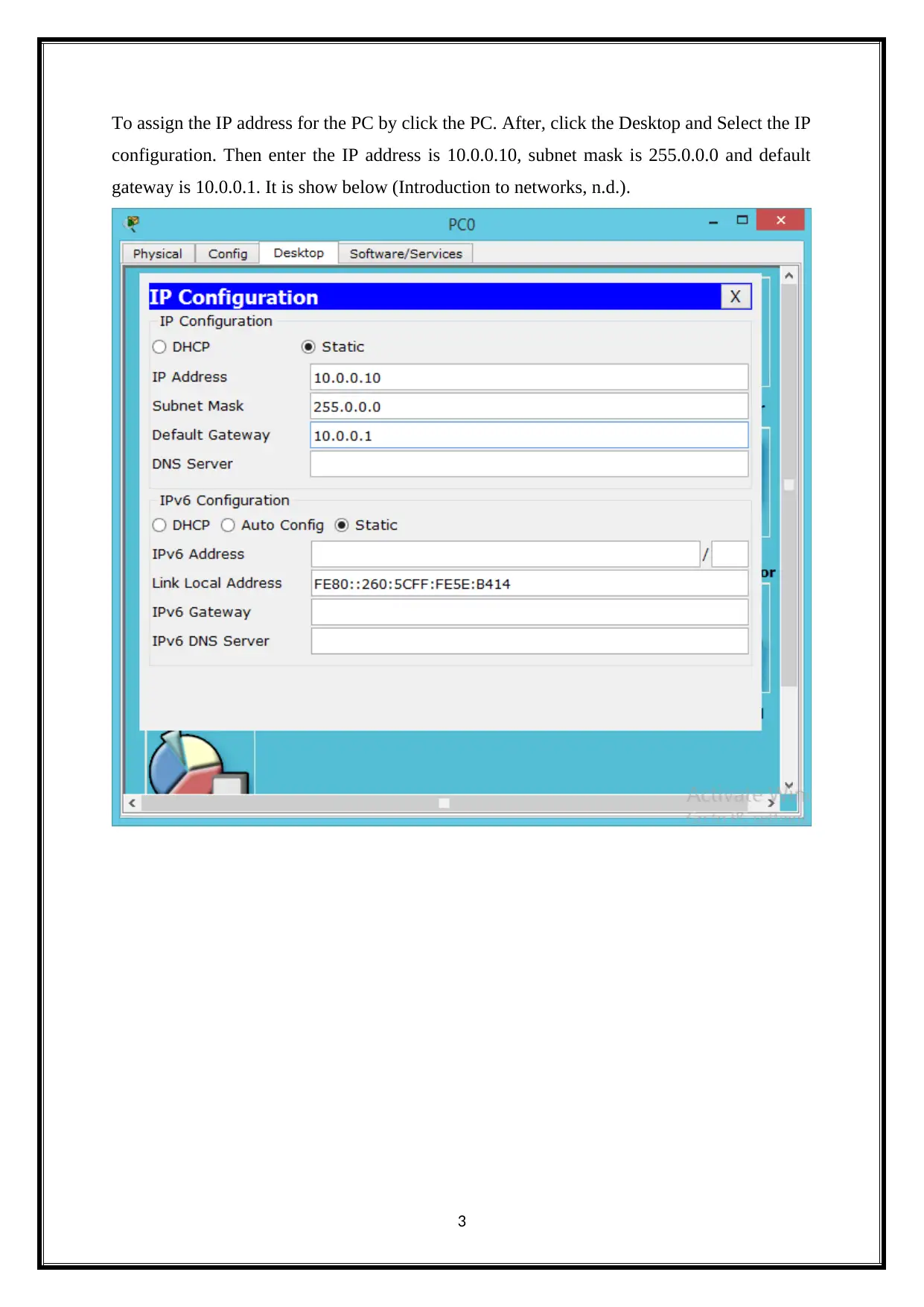
In PC0,
2
⊘ This is a preview!⊘
Do you want full access?
Subscribe today to unlock all pages.

Trusted by 1+ million students worldwide

configuration. Then enter the IP address is 10.0.0.10, subnet mask is 255.0.0.0 and default
gateway is 10.0.0.1. It is show below (Introduction to networks, n.d.).
3
Paraphrase This Document

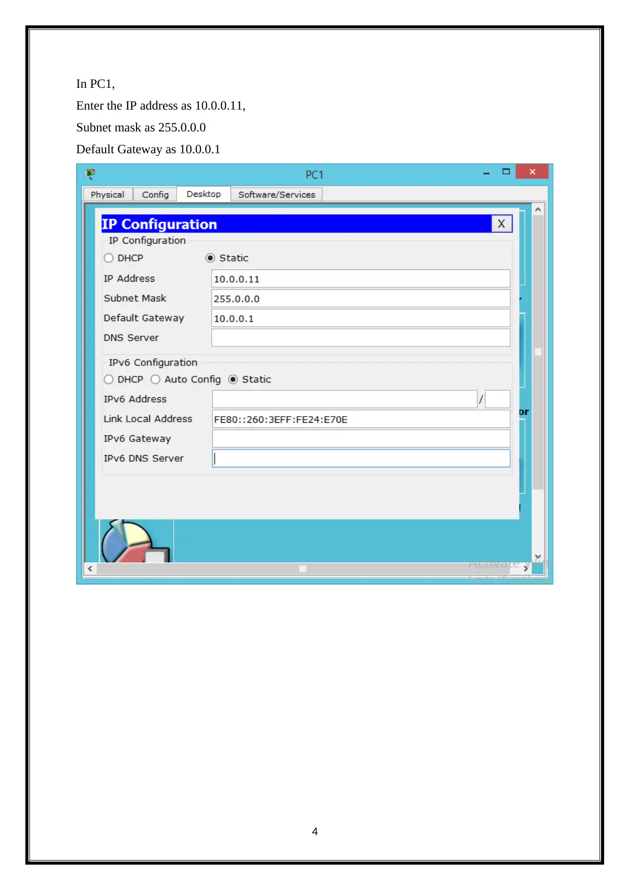
Enter the IP address as 10.0.0.11,
Subnet mask as 255.0.0.0
Default Gateway as 10.0.0.1
4

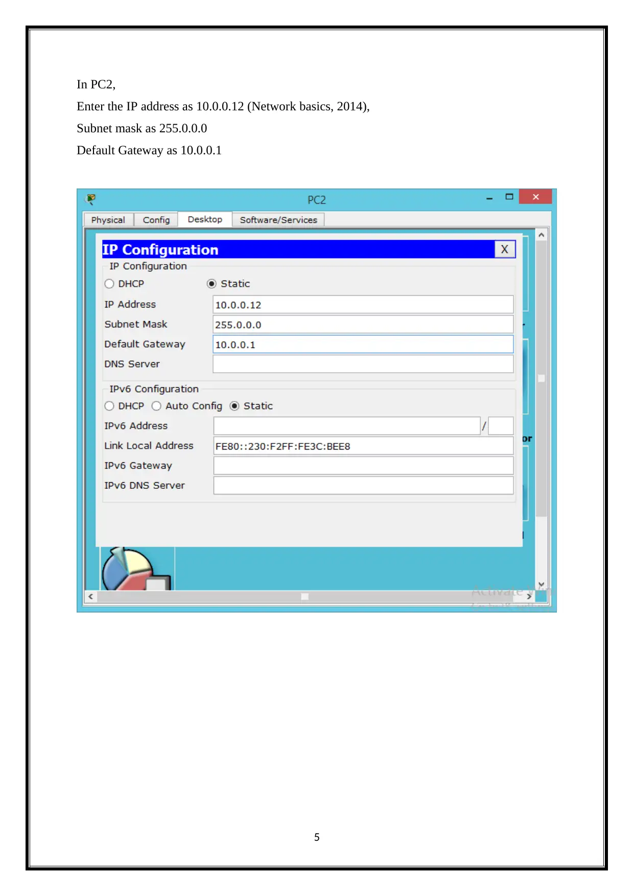
Enter the IP address as 10.0.0.12 (Network basics, 2014),
Subnet mask as 255.0.0.0
Default Gateway as 10.0.0.1
5
⊘ This is a preview!⊘
Do you want full access?
Subscribe today to unlock all pages.

Trusted by 1+ million students worldwide

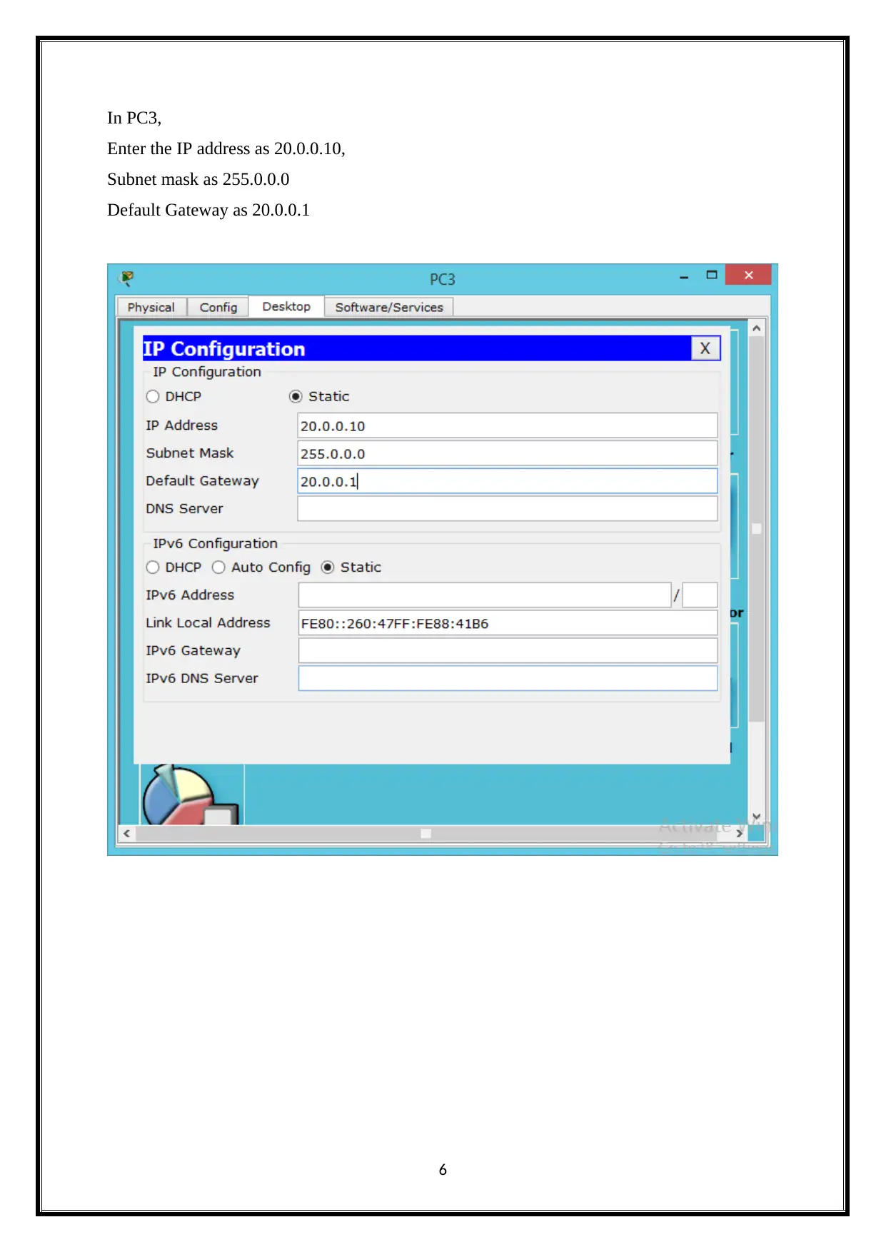
Enter the IP address as 20.0.0.10,
Subnet mask as 255.0.0.0
Default Gateway as 20.0.0.1
6
Paraphrase This Document

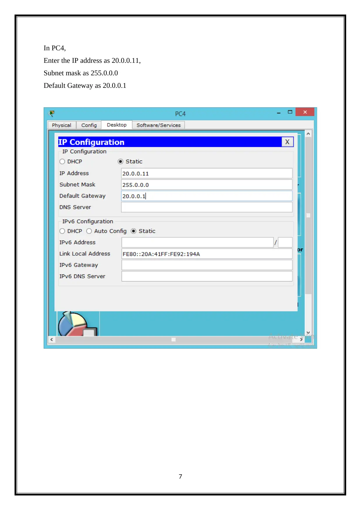
Enter the IP address as 20.0.0.11,
Subnet mask as 255.0.0.0
Default Gateway as 20.0.0.1
7

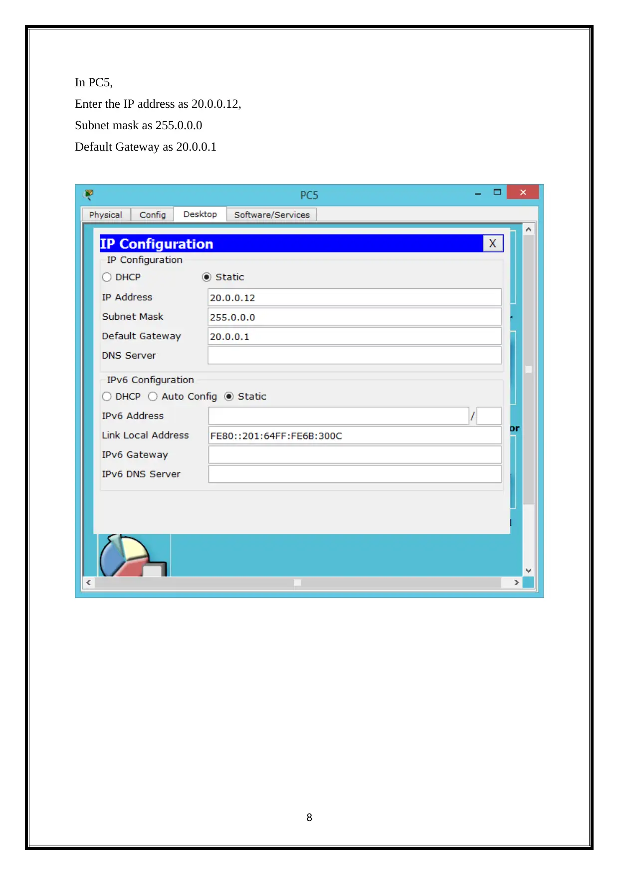
Enter the IP address as 20.0.0.12,
Subnet mask as 255.0.0.0
Default Gateway as 20.0.0.1
8
⊘ This is a preview!⊘
Do you want full access?
Subscribe today to unlock all pages.

Trusted by 1+ million students worldwide

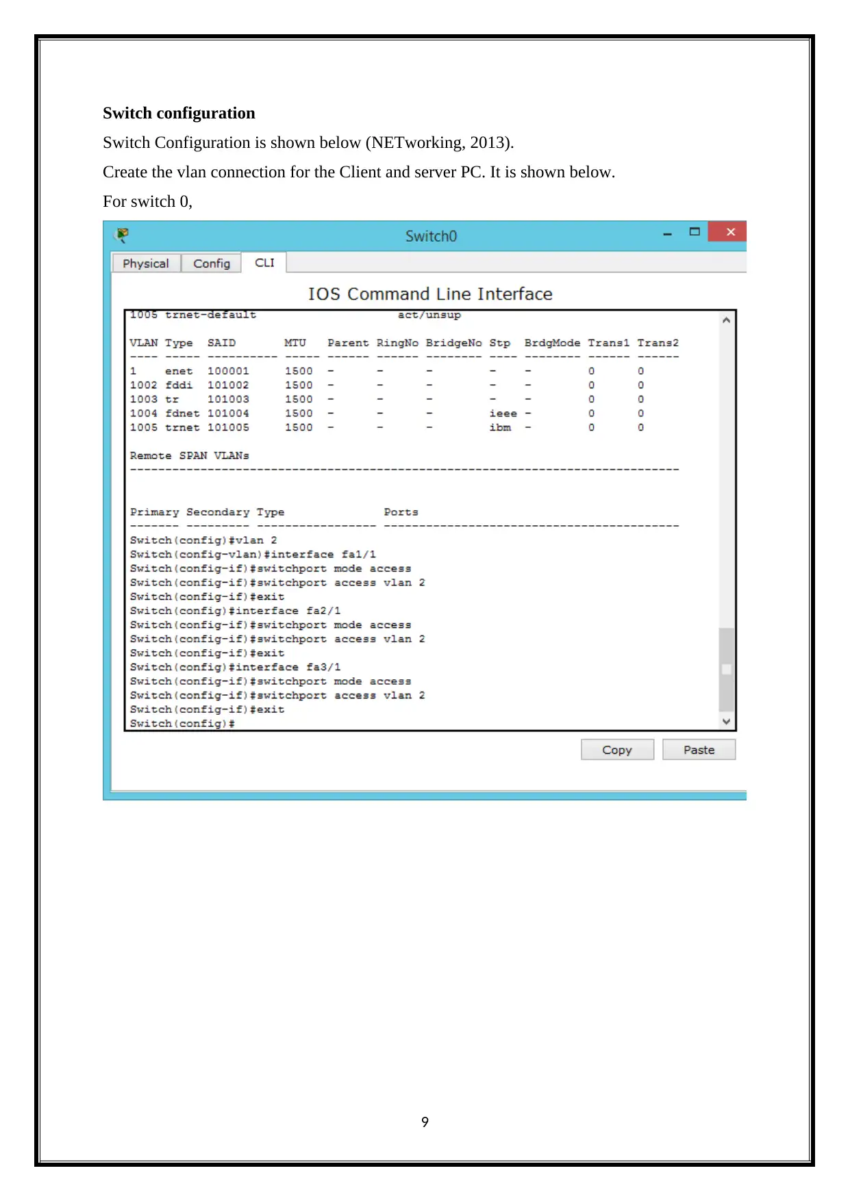
Switch Configuration is shown below (NETworking, 2013).
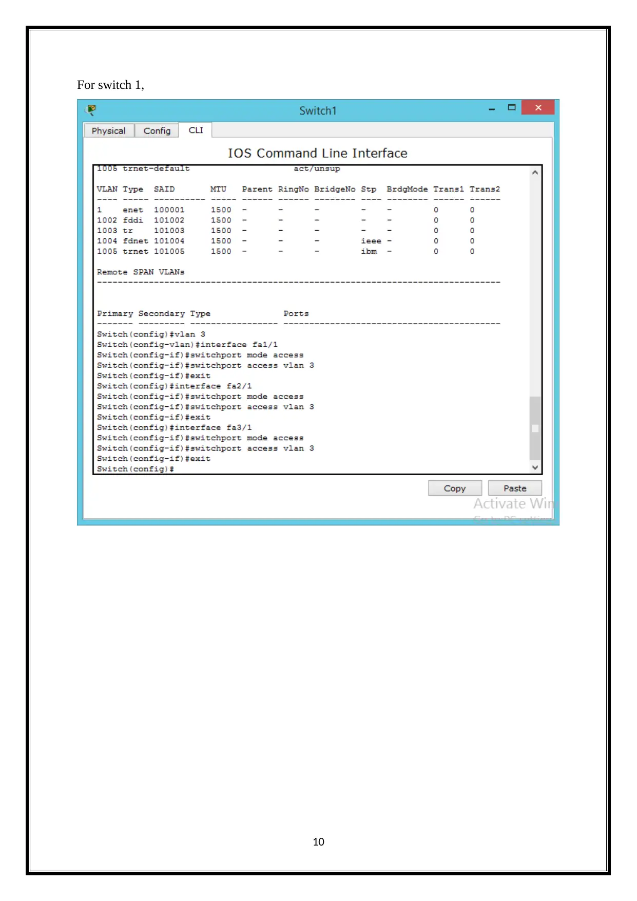
Create the vlan connection for the Client and server PC. It is shown below.
For switch 0,
9
Paraphrase This Document

10

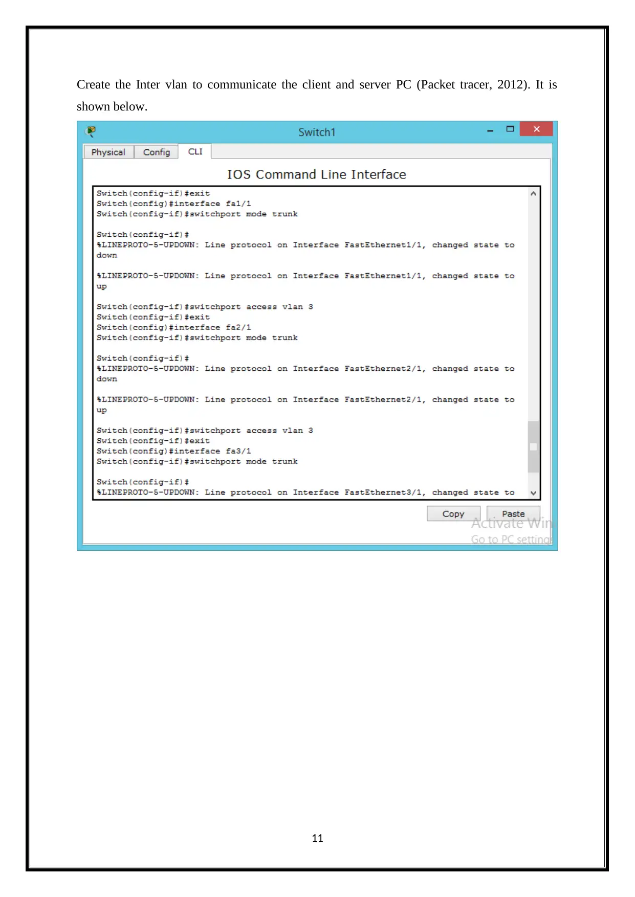
shown below.
11
⊘ This is a preview!⊘
Do you want full access?
Subscribe today to unlock all pages.

Trusted by 1+ million students worldwide

In Router 0,
Enter the interface as fa0/0
IP address as 10.0.0.9
Subnet mask as 255.0.0.0
12
Paraphrase This Document

Enter the interface as se2/0
IP address as 10.0.0.8
Subnet mask as 255.0.0.0
13

Enter the interface as fa1/0
IP address as 20.0.0.9
Subnet mask as 255.0.0.0
14
⊘ This is a preview!⊘
Do you want full access?
Subscribe today to unlock all pages.

Trusted by 1+ million students worldwide

Enter the interface as se2/0
IP address as 30.0.0.12
Subnet mask as 255.0.0.0
15
Paraphrase This Document

Enter the interface as fa0/0
IP address as 40.0.0.11
Subnet mask as 255.0.0.0
16

The above network design is done by using the cisco packet tracer. The network
design provides the productivity and security for the network. The Network design contain
the two routers (Scaling networks companion guide, n.d.). These are interconnecting by using
the IP route command. It provides the communication between the two routers. The network
design has the one or more network problems. To identify the network issues by using the
Trace route command. It tracing the network problems. It using the tracert utility to identify
the network issues. The DHCP connection was successfully configured.
17
⊘ This is a preview!⊘
Do you want full access?
Subscribe today to unlock all pages.

Trusted by 1+ million students worldwide

The IP routing is the process of transmit the packets from a one host to another host and
is done by using the routers. The IP routing is implemented, managed and operated by the
routers. The routers are easily determined the packet destination IP address and next hop
address. The router using the routing tables to easily determine the next hop address. It
finally forwards the packet to the destination host. It using the routing methodologies of the
IP packets across the IP networks. It includes the practices and methods of classless inter
domain routing. It contains the one or more information includes the IP addresses of the
destination and source devices and packet numbers (Connecting networks companion guide,
2014).
IP routing between the router is shown below.
In Router 0,
Enter the below command in command line interface.
ip route 20.0.0.0 255.0.0.0 10.0.0.0
It is shown below.
18
Paraphrase This Document

Enter the below command in command line interface.
ip route 10.0.0.0 255.0.0.0 20.0.0.0
19

Here pings the client own interface (Kenyon, 2002).
20
⊘ This is a preview!⊘
Do you want full access?
Subscribe today to unlock all pages.

Trusted by 1+ million students worldwide

21
Paraphrase This Document

22

The trace route command commonly using the one or more utility to identify the network
problems. Here using the tracert utility. It is used to easily identifies the network problems.
The tracert command is used to display the packet path details. It determines the IP route to a
destination by transmitting the Internet control Message protocol. It easily determines the
network trouble shooting on the network. It is one of computer network diagnostic tool for
display the packet path and measuring the delay of packets across the network. It has the time
to live value to determine the intermediate routers. It sends the packets with the time to live
values.
23
⊘ This is a preview!⊘
Do you want full access?
Subscribe today to unlock all pages.

Trusted by 1+ million students worldwide

24
Paraphrase This Document


4.1 DHCP connection
DHCP configuration is shown below.
In Router 0,
It is shown below.
26
⊘ This is a preview!⊘
Do you want full access?
Subscribe today to unlock all pages.

Trusted by 1+ million students worldwide

First click the Client PC or Server PC.
Click the desktop and select the IP configuration.
Choose the DHCP.
It automatically provides the IP address for the PC.
27
Paraphrase This Document

Enter the below command in CLI window.
It is shown below.
28

First click the Client PC or Server PC.
Click the desktop and select the IP configuration.
Choose the DHCP.
It automatically provides the IP address for the PC.
29
⊘ This is a preview!⊘
Do you want full access?
Subscribe today to unlock all pages.

Trusted by 1+ million students worldwide

To configure the web server by follows the below steps.
Click server and select the web Browser.
Enter the IP address in the URL.
30
Paraphrase This Document

To configure the DNS server by using the below steps.
First click the server and select the services.
After click the DNS.
In DNS services,
Choose the DNS service ON.
Enter the resource records as,
Name is www.csu.edu.au
Address is 30.0.0.1
And Save the DNS service records.
It is shown below.
31

IP address is 30.0.0.1. It is shown below.
32
⊘ This is a preview!⊘
Do you want full access?
Subscribe today to unlock all pages.

Trusted by 1+ million students worldwide

It is shown below.
33
Paraphrase This Document


Enter the URL in the web browser.
It is shown below (Oppenheimer, 2011).
35
⊘ This is a preview!⊘
Do you want full access?
Subscribe today to unlock all pages.

Trusted by 1+ million students worldwide

The Firewall connection is used to provide the secure connection. The firewall is a one of the
network security device that rejects and grants the network access to the traffic flows between
the trusted and untrusted zone. The firewall configuration is done by creating the complex
PDU in the network. It blocks the network traffic between the client and server. It mainly
used to reduce the network problems. It blocks the network traffic by creating he complex
PDU in the network.
To create the PDU by enter the,
Destination IP address as 10.0.0.10
Source IP address as 20.0.0.11
Sequence Number as 2
One-shot time is 2 seconds.
It is shown below.
36
Paraphrase This Document

The simple network setup is successfully created by using the cisco packet tracer. The
simple network design contains the cisco network devices like cisco switches, cisco routers,
cisco server and PC. These are connected with each other. The cisco network devices are
used to reduce the operational and business costs. The cisco Router, switch and PC
configurations are successfully configured and these are analysed in detail. The Client and
Server Ping connection is successfully done. The client pings their own gateway and server.
The network problems are easily addressed by using the trace route command. The trace
route command using the more than one utility to address the network issues. The DHCP
connection also successfully configured and analysed. The Web server, DNS server also
configured successfully and discussed in detail. The Firewall also configured. It provides the
secure connection for the network. It easily blocks the TCP traffic between the client and
server connection.
37

Connecting networks companion guide. (2014). Indianapolis, IN.
Introduction to networks.
Jesin, A. (2014). Packet Tracer Network Simulator. Birmingham: Packt Publishing.
Kenyon, T. (2002). High-performance data network design. Boston: Digital Press.
Network basics. (2014).
NETworking. (2013). [Hong Kong].
Oppenheimer, P. (2011). Top-down network design. Indianapolis, Ind.: Cisco Press.
Packet tracer. (2012). [Place of publication not identified].
Scaling networks companion guide.
38
⊘ This is a preview!⊘
Do you want full access?
Subscribe today to unlock all pages.

Trusted by 1+ million students worldwide