MITS5502 Assignment 3: City Glazier Software Specification Document
VerifiedAdded on 2022/10/16
|20
|2776
|481
Report
AI Summary
This document provides a comprehensive Software Requirements Specification (SRS) for the City Glazier Company. It begins with an executive summary and system description, outlining the company's needs for a new supply system. The document defines the scope, feasibility analysis, and both functional and non-functional requirements, including safety and security measures. It details product features, use case and context diagrams, and functional models. Furthermore, the report includes design elements such as architectural design, hardware and software requirements, class diagrams, interface designs, activity diagrams, BPMN 2.0 diagrams, sequence diagrams, interaction diagrams, and state diagrams. Finally, the report concludes with a discussion of the client-server system architecture.
City Glazier Company
Software Requirements Specification
Supply System for City Glazier Company
Software Requirements Specification
Supply System for City Glazier Company
Paraphrase This Document
Need a fresh take? Get an instant paraphrase of this document with our AI Paraphraser
Contents
Specification Document...............................................................................................................1
INTRODUCTION.......................................................................................................................1
a) Executive summary..............................................................................................................1
b) System description................................................................................................................1
c) Purpose of the system...........................................................................................................1
d) Scope.....................................................................................................................................1
e) Feasibility analysis................................................................................................................1
f) REQUIREMENTS...............................................................................................................2
Functional Requirements.............................................................................................................2
Non- Functional Requirements....................................................................................................2
Safety measures............................................................................................................................2
Security Requirement measures...................................................................................................2
Software Quality..........................................................................................................................2
g) Assumptions/Constraints......................................................................................................3
h) Product Features...................................................................................................................3
i) Use case diagram.....................................................................................................................3
i) Context model.......................................................................................................................4
j) Level set Functional model...................................................................................................5
Design Document.........................................................................................................................5
a) Executive Summary..............................................................................................................5
b) Architectural Design.............................................................................................................5
c) Hardware Requirements.......................................................................................................6
d) Software Requirements.........................................................................................................6
e) Class diagram design............................................................................................................6
f) Interface Design.....................................................................................................................8
......................................................................................................................................................9
g) Activity Diagram................................................................................................................10
h) BUSINESS PROCESS MODEL NOTATION using BPMN 2.0......................................11
i) Sequence diagram...............................................................................................................12
1
j) Interaction Diagram............................................................................................................13
....................................................................................................................................................13
k) State Diagram.....................................................................................................................13
l) System Architecture............................................................................................................14
Clint-Server Architecture...........................................................................................................14
Conclusion.................................................................................................................................15
Reference...................................................................................................................................16
2
⊘ This is a preview!⊘
Do you want full access?
Subscribe today to unlock all pages.
Trusted by 1+ million students worldwide
Specification Document
INTRODUCTION
a) Executive summary
City Glazier Company supplies glass for windows and doors for both large scale and small scale
construction sites. The business has been running since 2001. The company started with one
track and has now increased to eleven tracks making it efficient for transport services within the
company. It has also expanded and opened other branches of its own around the city.
As a result of this expansion the company tends to link with glass manufacturers directly and
also create a system that will enhance efficiency as a result of it expanding. This will make the
company handle huge amount of data, making it possible for it to make appropriate decisions
when it comes to decision making process.
b) System description
The purpose of this document is to showcase City Glazier's new system that the company will
use in ensuring that it has efficiently supply its services and product to its precise consumer. As
per now the company still operates under the manual based system. This makes it difficult to
record sales that occur daily since the company has grown in size (Azar & Vaidyanathan,2015).
As a result of this growth, the company is required to make some advancement that will suit its
growth rate and also put all the records as they are supposed to be. The company will also ensure
that its branches are well connected to allow easy flow of reports from one branch to another.
The system will also incorporate a new payment system which will make it easier for customers
to pay for products and services via PayPal and email.
c) Purpose of the system
The following are some of the reasons why this system is being built:
Ensuring that transactions are accurately recorded.
Creating new payment methods.
d) Scope
The system links City glazier to its manufacturers and also ensures that goods are being tracked
according to when it’s being transported. While the software requirement specification shows
how the system is integrated into one another.
e) Feasibility analysis
This analysis is used to show the loop holes that exist from the system being used by the
company. It is also used in gathering information that are required by the people who are going
3
Paraphrase This Document
Need a fresh take? Get an instant paraphrase of this document with our AI Paraphraser
to use the system (Dennis, Wixom, & Roth,2018). In our case the consumers are requesting
payment system to be made in such a way that will enable them pay via PayPal and emails.
f) REQUIREMENTS
Functional Requirements
Personal details about consumers will be secured during online registration.
The system will also generate reports on invoices that have not been paid for.
The consumers will be able to register for them to get an account.
Staffs from large projects will be able to send response to companies that have sent their
response forms.
Branches from different parts of the city will be able to transfer data to one another.
The users will be able to open files that contain their invoices for reference purposes.
Non- Functional Requirements
Safety measures
Consumers are always given three to four extra glasses when they do their purchase which caters
to the loss they may incur in case some break during transportation (Dennis, Wixom, &
Tegarden, 2009).
Signs and posters have been placed to remind people of safety measures while they are in the
firm.
Security Requirement measures
Appropriate data encryption techniques have been used to prevent data from being accessed by
unauthorized user when being sent to another branch.
Software Quality
AVAILABILITY: hosting is done on the server making the system to be always available.
CORRECTNESS: All records should be generated accordingly since they are all contained in the
database
MAINTAINABILITY: The system should be accurate when it comes to scheduling of time in
different activities.
USABILITY: Users should find it easy to use and it should be able to satisfy relative all their
needs.
4
g) Assumptions/Constraints
It is assumed that the system will work best when installed in windows due to the specifications
be considered during the development of the system.
It is assumed that the system will not be hacked easily due to security measures taken into
consideration at the beginning of the project.
It is assumed that the system will always be available for use at all times.
h) Product Features
The major features of this system area listed below.
The system ensures only authorized users are the ones using the system.
The system helps the administrator in tracing of goods from one place to another.
It provides efficiency in terms of how records are being handled.
It increases the rate of production since the company is linked to manufacturing firms making it
easier to know when the quantity of stock is low.
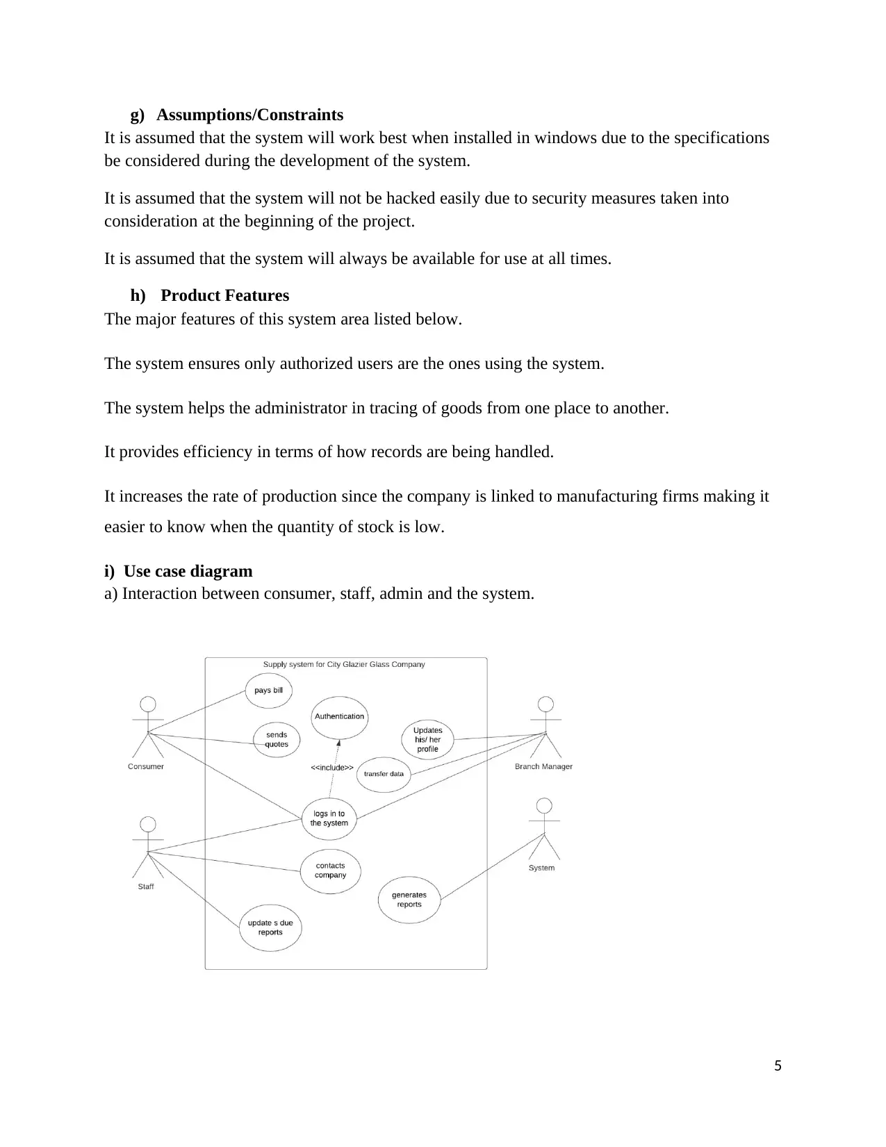
i) Use case diagram
a) Interaction between consumer, staff, admin and the system.
5
It is assumed that the system will work best when installed in windows due to the specifications
be considered during the development of the system.
It is assumed that the system will not be hacked easily due to security measures taken into
consideration at the beginning of the project.
It is assumed that the system will always be available for use at all times.
h) Product Features
The major features of this system area listed below.
The system ensures only authorized users are the ones using the system.
The system helps the administrator in tracing of goods from one place to another.
It provides efficiency in terms of how records are being handled.
It increases the rate of production since the company is linked to manufacturing firms making it
easier to know when the quantity of stock is low.
i) Use case diagram
a) Interaction between consumer, staff, admin and the system.
5
⊘ This is a preview!⊘
Do you want full access?
Subscribe today to unlock all pages.
Trusted by 1+ million students worldwide
Admin can update his/her profile which stands for the system itself, likewise, the staff and the
consumer can log in and update their profile too. This use case diagram is used to show the
actors and the description of how a system works. In this case, we have the following actors and
description.
b) Use Case Description
Actor Description
Consumers They can pay the bill
They can send quotes to the company
They can also log in to the system
System It generates reports that are required by the company every month
Staff They contact companies that have sent their quotes
They update reports on payments that have not been paid
Admin Can send reports to other branches
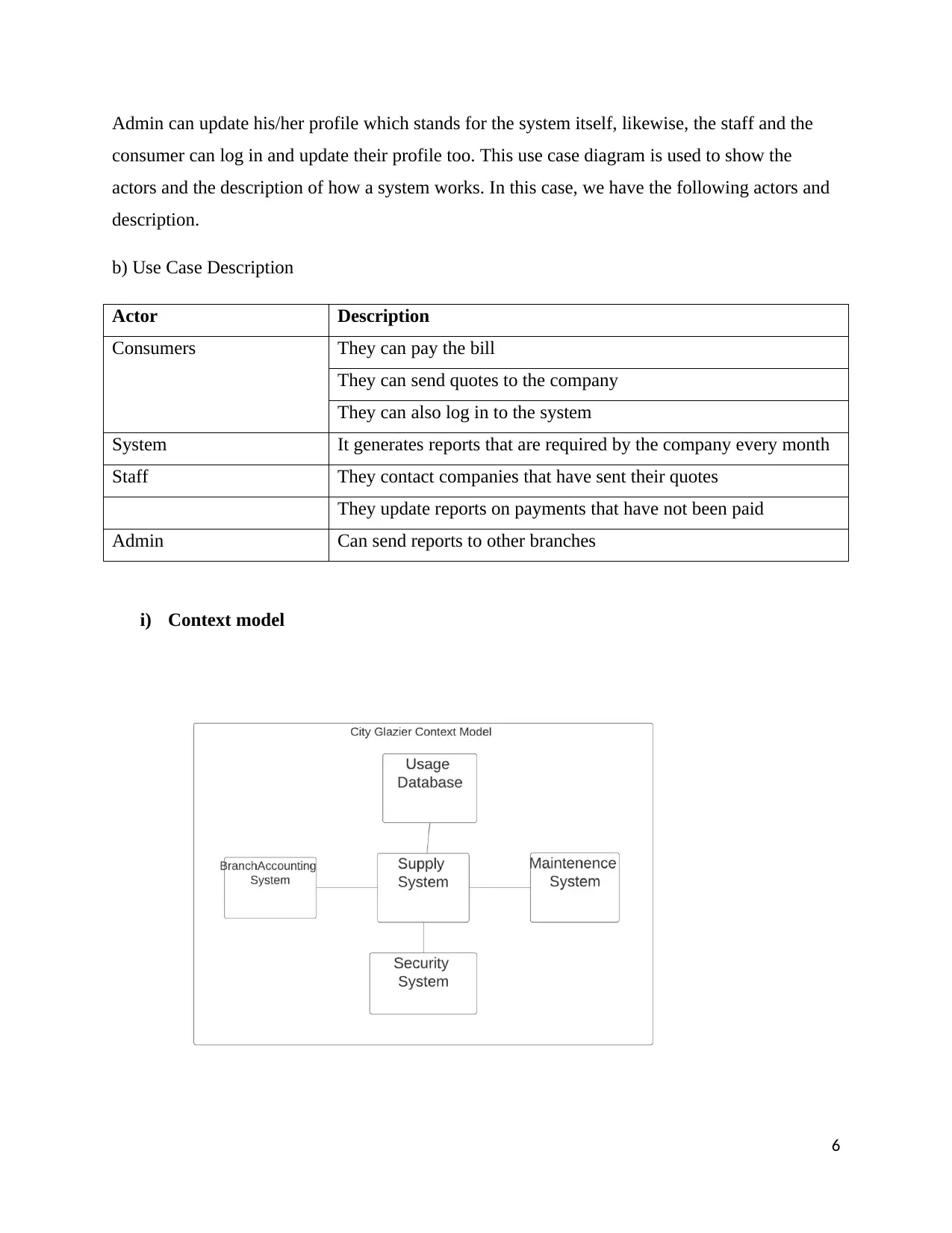
i) Context model
6
consumer can log in and update their profile too. This use case diagram is used to show the
actors and the description of how a system works. In this case, we have the following actors and
description.
b) Use Case Description
Actor Description
Consumers They can pay the bill
They can send quotes to the company
They can also log in to the system
System It generates reports that are required by the company every month
Staff They contact companies that have sent their quotes
They update reports on payments that have not been paid
Admin Can send reports to other branches
i) Context model
6
Paraphrase This Document
Need a fresh take? Get an instant paraphrase of this document with our AI Paraphraser
The above context diagram shows how the company co-exists with both its internal and external
affairs. From this one is able to know the types of servers and networks that will be used in
merge the branches to one distribution source depending with type of server that will be put to
place when designing.
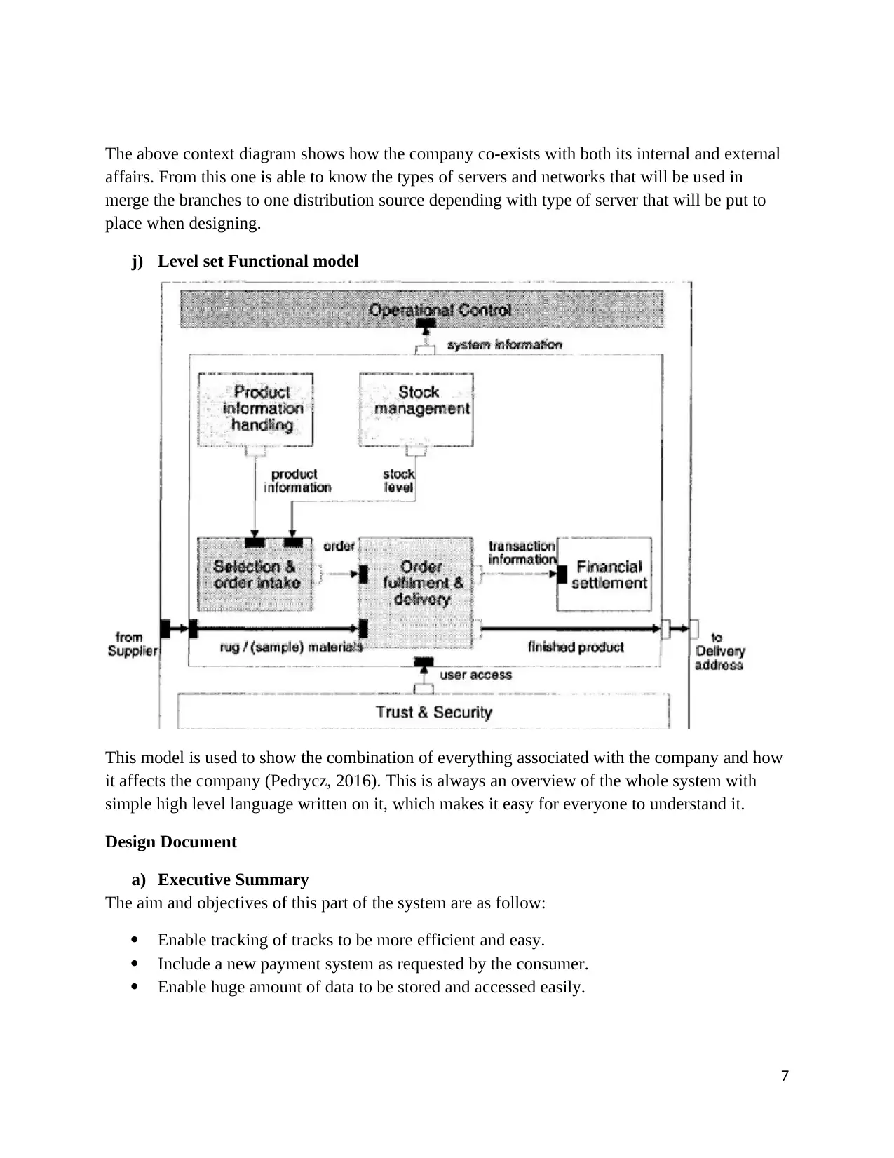
j) Level set Functional model
This model is used to show the combination of everything associated with the company and how
it affects the company (Pedrycz, 2016). This is always an overview of the whole system with
simple high level language written on it, which makes it easy for everyone to understand it.
Design Document
a) Executive Summary
The aim and objectives of this part of the system are as follow:
Enable tracking of tracks to be more efficient and easy.
Include a new payment system as requested by the consumer.
Enable huge amount of data to be stored and accessed easily.
7
affairs. From this one is able to know the types of servers and networks that will be used in
merge the branches to one distribution source depending with type of server that will be put to
place when designing.
j) Level set Functional model
This model is used to show the combination of everything associated with the company and how
it affects the company (Pedrycz, 2016). This is always an overview of the whole system with
simple high level language written on it, which makes it easy for everyone to understand it.
Design Document
a) Executive Summary
The aim and objectives of this part of the system are as follow:
Enable tracking of tracks to be more efficient and easy.
Include a new payment system as requested by the consumer.
Enable huge amount of data to be stored and accessed easily.
7
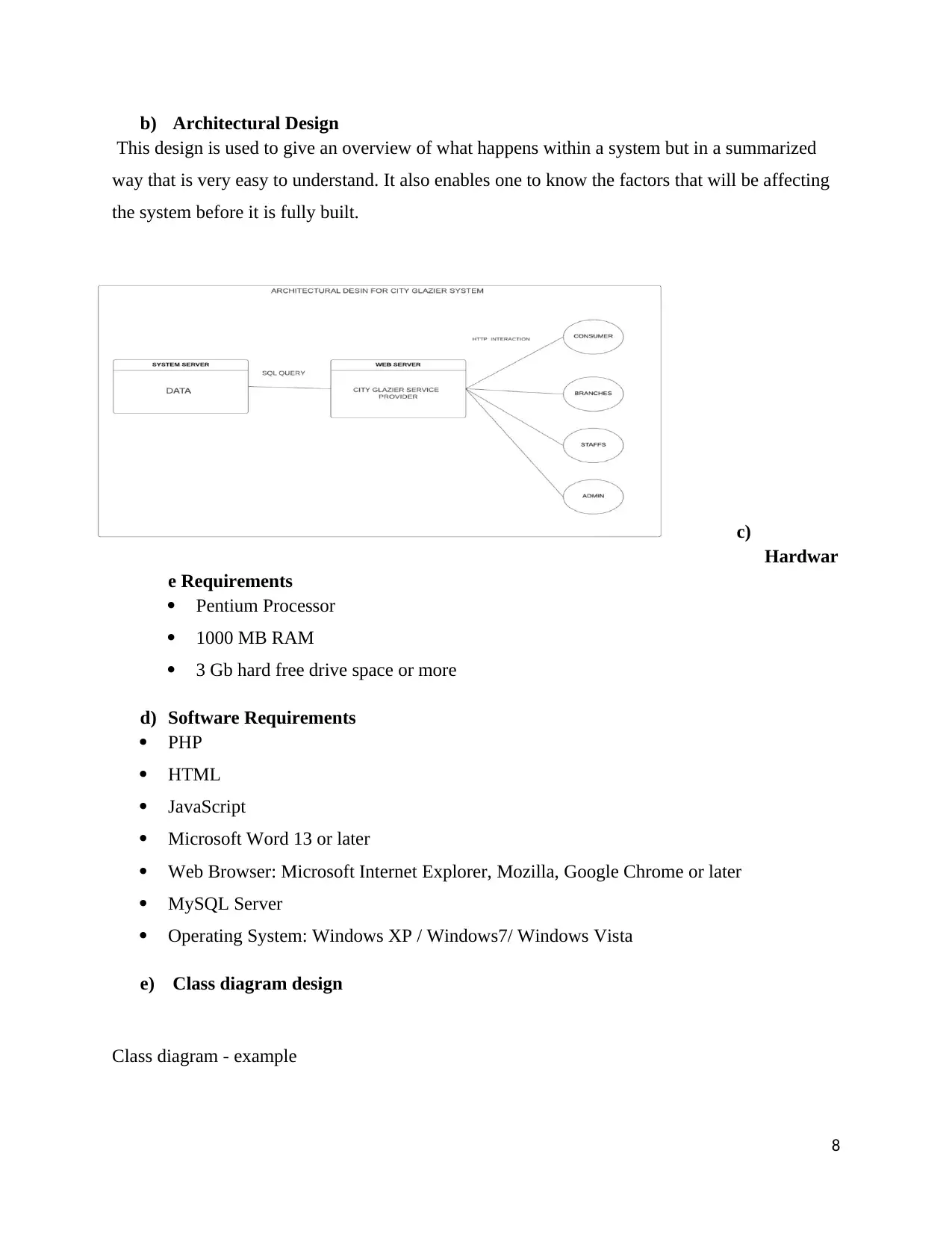
b) Architectural Design
This design is used to give an overview of what happens within a system but in a summarized
way that is very easy to understand. It also enables one to know the factors that will be affecting
the system before it is fully built.
c)
Hardwar
e Requirements
Pentium Processor
1000 MB RAM
3 Gb hard free drive space or more
d) Software Requirements
PHP
HTML
JavaScript
Microsoft Word 13 or later
Web Browser: Microsoft Internet Explorer, Mozilla, Google Chrome or later
MySQL Server
Operating System: Windows XP / Windows7/ Windows Vista
e) Class diagram design
Class diagram - example
8
⊘ This is a preview!⊘
Do you want full access?
Subscribe today to unlock all pages.
Trusted by 1+ million students worldwide
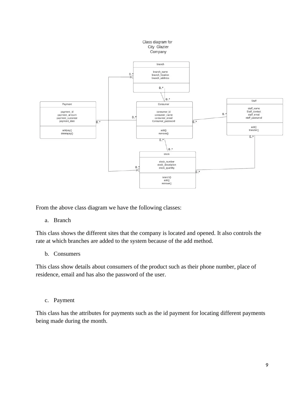
From the above class diagram we have the following classes:
a. Branch
This class shows the different sites that the company is located and opened. It also controls the
rate at which branches are added to the system because of the add method.
b. Consumers
This class show details about consumers of the product such as their phone number, place of
residence, email and has also the password of the user.
c. Payment
This class has the attributes for payments such as the id payment for locating different payments
being made during the month.
9
Paraphrase This Document
Need a fresh take? Get an instant paraphrase of this document with our AI Paraphraser
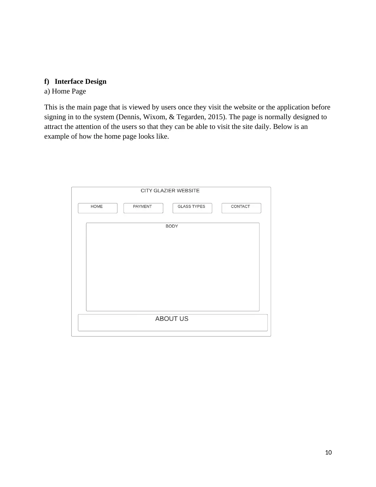
f) Interface Design
a) Home Page
This is the main page that is viewed by users once they visit the website or the application before
signing in to the system (Dennis, Wixom, & Tegarden, 2015). The page is normally designed to
attract the attention of the users so that they can be able to visit the site daily. Below is an
example of how the home page looks like.
10
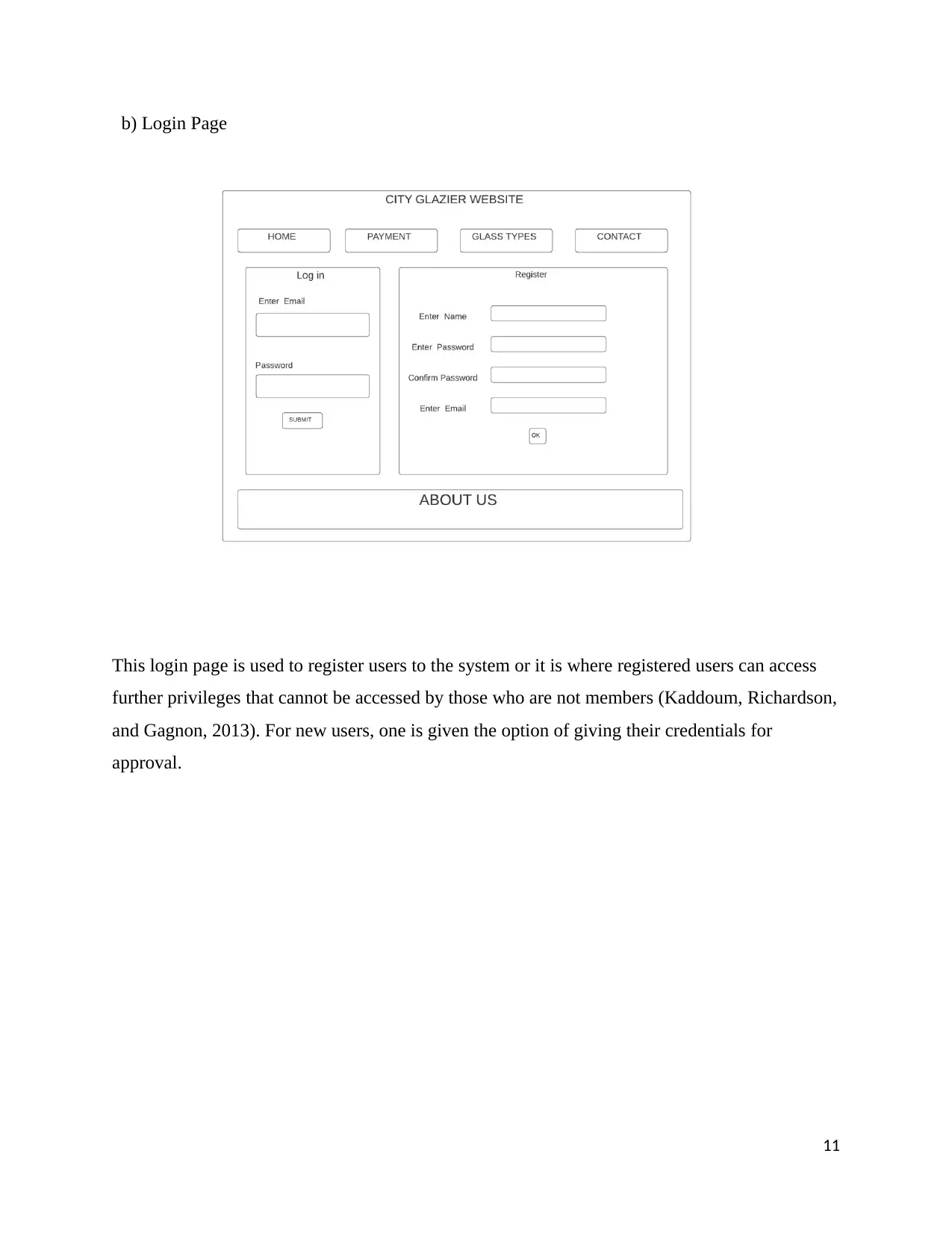
b) Login Page
This login page is used to register users to the system or it is where registered users can access
further privileges that cannot be accessed by those who are not members (Kaddoum, Richardson,
and Gagnon, 2013). For new users, one is given the option of giving their credentials for
approval.
11
This login page is used to register users to the system or it is where registered users can access
further privileges that cannot be accessed by those who are not members (Kaddoum, Richardson,
and Gagnon, 2013). For new users, one is given the option of giving their credentials for
approval.
11
⊘ This is a preview!⊘
Do you want full access?
Subscribe today to unlock all pages.
Trusted by 1+ million students worldwide
1 out of 20
Related Documents


Your All-in-One AI-Powered Toolkit for Academic Success.
+13062052269
info@desklib.com
Available 24*7 on WhatsApp / Email
![[object Object]](/_next/static/media/star-bottom.7253800d.svg)
Unlock your academic potential
Copyright © 2020–2026 A2Z Services. All Rights Reserved. Developed and managed by ZUCOL.