Civil Engineering Project: Beam Design, Analysis, and Safety

Verified

Added on  2022/12/27

|28
|4329
|4
Project
AI Summary
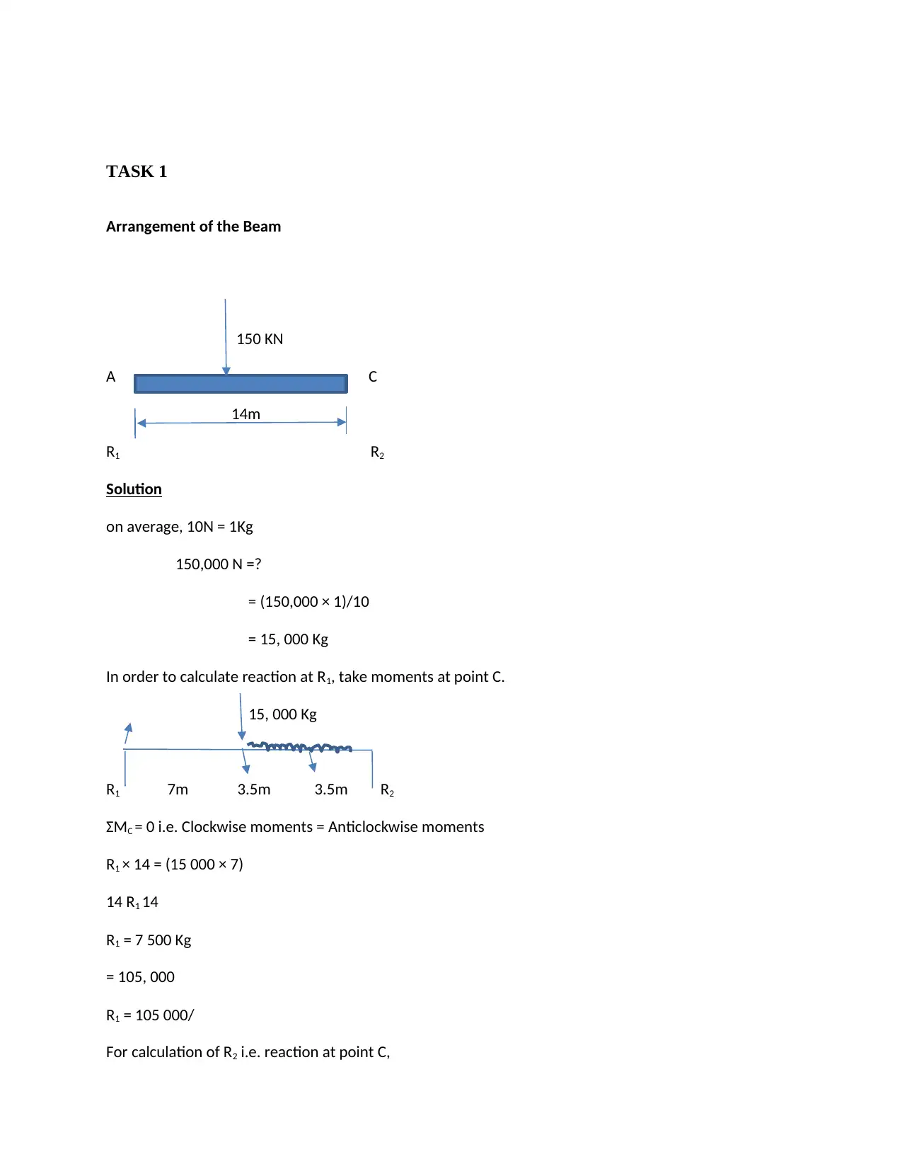
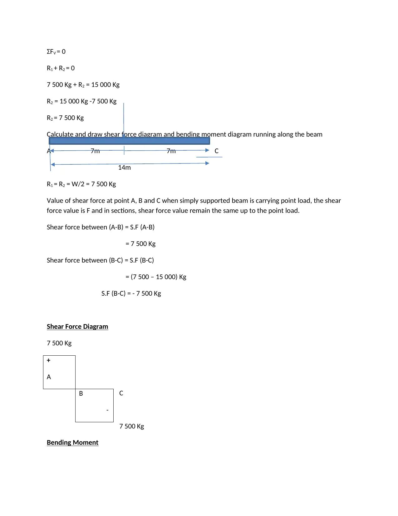
This civil engineering project encompasses a comprehensive analysis of beam design, including shear force and bending moment diagrams, deflection calculations, and the application of the factor of safety. The project begins with an introduction to the importance of safe design in construction, emphasizing the early elimination of hazards. Task 1 focuses on the calculation of reactions, shear force diagrams, and bending moment diagrams for various beam configurations under point loads and distributed loads. It then delves into safe design principles, covering aspects like clearance, pre-fabrication, and material selection to ensure structural integrity and worker safety. The project further examines design considerations for safe application and maintenance. Task 2 explores deflection calculations for uniformly distributed loads and the impact of beam deflections on structural stability, including the potential for concrete cracking and steel corrosion. The calculations are detailed, and the effects of deflections are discussed.
Document Page
INDIVIDUAL PROJECT
By Name
Course
Instructor
Institution
Location
Date
tabler-icon-diamond-filled.svg

Paraphrase This Document

Need a fresh take? Get an instant paraphrase of this document with our AI Paraphraser
Document Page
Introduction
It is usually easier and cheaper to effectively eliminate hazards at the planning or design phase
than making changes later once the hazards has turned out to be actual risk in the place of work.
Concrete is one among the different materials such as those for binding (combination of fly ash
and cement), coarse aggregate, and fine aggregate together with water. Currently, the costs
incurred in construction are extremely high by the application of conventional materials as a
result of insufficient natural materials. The situation can however be rectified by totally replacing
concrete material with other sufficient materials of desired properties. But because of insufficient
materials which are of more importance as concrete, there is need to use waste materials for
partial replacement of the components of concrete. According to the survey which was
conducted by the association of World Coal in the year 2010, it was identified that billions tons
of cement were used worldwide and was accompanied by emissions of large amounts of carbon
dioxide into the environment which is of more dangerous to the living.
Partial replacement of cement with other materials that bear desired features promises a
reduction in the amount of carbon dioxide emitted into the atmosphere and a save on the natural
materials. Disposing of the industrial wastes to the nearest locations causes pollution to the
atmosphere and land and mostly affects the aesthetics of the urban areas. Therefore it is more
friendly to the environment and cost effective to apply the waste substances in the cements as a
proper means of disposing the waste materials. This study mainly aims at providing a selection
on the waste materials with required features for the concrete. The study incorporates the
analysis which was done prior concerning the chemical and mechanical properties of concrete
generated by use of waste materials to partially replace the cement.
Document Page
TASK 1
Arrangement of the Beam
150 KN
A C
14m
R1 R2
Solution
on average, 10N = 1Kg
150,000 N =?
= (150,000 × 1)/10
= 15, 000 Kg
In order to calculate reaction at R1, take moments at point C.
15, 000 Kg
R1 7m 3.5m 3.5m R2
ΣMC = 0 i.e. Clockwise moments = Anticlockwise moments
R1 × 14 = (15 000 × 7)
14 R1 14
R1 = 7 500 Kg
= 105, 000
R1 = 105 000/
For calculation of R2 i.e. reaction at point C,
Document Page
ΣFV = 0
R1 + R2 = 0
7 500 Kg + R2 = 15 000 Kg
R2 = 15 000 Kg -7 500 Kg
R2 = 7 500 Kg
Calculate and draw shear force diagram and bending moment diagram running along the beam
A 7m 7m C
14m
R1 = R2 = W/2 = 7 500 Kg
Value of shear force at point A, B and C when simply supported beam is carrying point load, the shear
force value is F and in sections, shear force value remain the same up to the point load.
Shear force between (A-B) = S.F (A-B)
= 7 500 Kg
Shear force between (B-C) = S.F (B-C)
= (7 500 – 15 000) Kg
S.F (B-C) = - 7 500 Kg
Shear Force Diagram
7 500 Kg
C
7 500 Kg
Bending Moment
+
A
B
-
tabler-icon-diamond-filled.svg

Paraphrase This Document

Need a fresh take? Get an instant paraphrase of this document with our AI Paraphraser
Document Page
In case of simply supported beam, bending moment will be zero. It will be maximum where shear force
is zero.
Bending moment at point A and C is
M (A) = M (C) = 0
Bending moment at point B is
M (B) = F × distance of R1 from point B
Bending at point B = 7 500 Kg × 2
= 15 000 kg - m
15 000 Kg - m
A B C
B.M.D
Part b
Task 1 (A)
(b) 65 KN
A B
2m 6m
8m
Document Page
65 KN
RA RB
Total ratio = 8
RA = (6 × 65)/8 RB = (2 × 65)/8
= 48.75 KN = 16.25 KN
+ 48.75 KN
-16.25 KN
S.F.D
1 2
X1 X2
B.M.D
Part C
Document Page
1/2
R 1/2 R
V
Shear
V
Max max moment
(d) Continuation
-RA → qVA = VA – (-RA) = 0 + (P1 + WL/2) - (P1 + WL/2)
VA1x=0 = (P1 + WL)/2 – W (0) = (P1 + WL)/2 – 0
V
(P1 + WL)/2
P1/2 P1
tabler-icon-diamond-filled.svg

Paraphrase This Document

Need a fresh take? Get an instant paraphrase of this document with our AI Paraphraser
Document Page
C = ½ B=L
-P1/2
-P1 + WL/2
Bending Moment Diagram
Bending moment diagram can be considered as the sum of bending moment due to the concentrated
and distributed load separately.
Part e
Document Page
Task 1(B)
Safe Design Definition:
Safe design for structural integrity refers to the integration of the measure of control in the
processes of the early design so as to eliminate risk or if that is not practically applicable,
Document Page
minimize risks to safety and health in the entire life of the structure which is being taken through
the design process.
Safe construction design
Designing of a structure is associated by some risks and the possible solutions include the
following:
Ensuring sufficient clearance for both the overhead lines of electricity and structure by
means of disconnecting, re-routing or burying the cables prior to commence of the
construction to avoid the possible contact that may occur during the operation on the
cranes as well as tall buildings.
Fabricating of mechanisms that allow either off-set or ground pre-fabrication to prevent
erecting or assembling at high lengths as well as to minimize the possibility of workers
falling from high heights or suffer injuries from the falling objects, for example, windows
are advisable to be fixed close to the ground surface before the panels are erected.
The height at which the parapets are designed should abide by the regulations of
guardrail, eradicating the necessity of guardrails construction as well as maintenance of
the roof in future.
Application of continual support beams in the double connections of beam-to-column,
either by addition of other holes for bolt, beam seat or extra redundant points of
connections in the course of connection process. This is likely to aid support for the
beams in the course of erection to ensure that, possible fallings that may occur from
vibrations that are unpredicted are eliminated, eradication of misalignment as well as
unpredicted loads on construction.
tabler-icon-diamond-filled.svg

Paraphrase This Document

Need a fresh take? Get an instant paraphrase of this document with our AI Paraphraser
Document Page
The stairways should be constructed and designed permanently to avoid the possible falls
as well as other related risks on the non-permanent stairs together with scaffolding, and
should be properly situated before the construction process begins.
Minimizing the space between the battens and trusses of the roof to ensure reduction of
falls internally when constructing the roofs.
Selecting necessary materials for construction with safe handling.
Reducing the size of pre-fabricated panels of the wall in cases access to the site is under
some restrictions.
Choosing paints or other materials that are used for finishing with low emissions of
volatile organic substance.
Indicating where necessary the length above as well as the position of all the lines of
electricity to help with the method of site safety.
The Design that Ensures Safe Application
The intended purpose of the structure should be considered accounting for the usage systems as
well as the equipment and machinery that may be applied in the operation.
Check on if the building may be subjected to some known risks like storage of harmful goods in
the warehouse, violence pertaining to occupation in job areas, or manual tasks in the health
facilities.
The possible control measures for the risks associated with the structure and its functions
include:
Designing traffic places to ensure that pedestrians and vehicles have separate areas of
operation.
Document Page
Application of materials which are non-slip on the surface of the ground especially in
places that are affected by weather or wet areas.
Issuing enough space for safe installation, operation as well as maintenance of the plant
together with the machinery.
Providing enough light for the necessary operations to be carried out within the structure.
Fabricating enough space that is capable of incorporating or accommodating the
mechanical tools to eradicate the risks of manual task.
Construction of sufficient access e.g., the hospital corridors should be wide enough to
cater for the movements of beds and wheelchairs.
The wall together with ceilings should be designed in a way that ensure reduction of
noise and allow acoustical treatments.
Designing a plant with low emission of noise or eliminating the noisy plant.
Constructing loadings of the floor in a manner which offer accommodation of heavy
machines applied in the construction process and to give a clear indication on the design
load documents for the various parts of the building.
The Design that Cater for Safe Maintenance
Task 1(C )
The ratio of the maximum stress that can be withstood by an object to the streets applied is
refered to as factor of safety. When the value of factor of safety is more than 1.This implies that
the stress applied is less than the maximum stress or have the same value. The object can
therefore withstand the force. When the value is equal to one, it means that the material is just
tough enough to withstand the load. When the factor of safety value is less than 1, it implies that
chevron_up_icon
1 out of 28
circle_padding
hide_on_mobile
zoom_out_icon
[object Object]